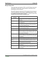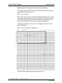
1
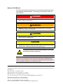
KeTop T40
Handheld Terminal
Serial T-Flex Coupling
User’s Manual V 1.1
Notes on This Manual
At various points in this manual you will see notes and precautionary warnings regarding possible hazards. The meaning of the symbols used is explained below.
! DANGER
z
DANGER indicates an imminently hazardous situation which, if not avoided, will
result in death or serious injury.
! WARNING
z
WARNING indicates a potentially hazardous situation which, if not avoided,
could result in death or serious injury.
! CAUTION
z
CAUTION indicates a potentially hazardous situation which, if not avoided, may
result in minor or moderate injury.
CAUTION
z
CAUTION used without the safety alert symbol indicates a potentially hazardous
situation which, if not avoided, may result in property injury.
This symbol reminds you of the possible consequences of touching
electrostatically sensitive components.
Note
Notes on use of equipment and useful practical tips are identified by the
“Notice” symbol. Notices do not contain any information that draws attention to potentially dangerous or harmful functions.
© KEBA 2005
Specifications are subject to change due to further technical developments. Details presented may be subject to correction. All
rights reserved.
Document: version 1.1 / material no.: 61907
Filename: t40_tflex_en.doc, last saving on: 13. 12. 2004
KEBA AG, Postfach 111, Gewerbepark Urfahr, A-4041 Linz
Tel.: ++43 / 732 / 70 90-0, Fax: ++43 / 732 / 73 09 10, E-Mail: [email protected], www.keba.com
KEBA GmbH, Ulmer Straße 123, D-73037 Göppingen
Tel.: ++49 / 7161 / 97 41-0*, Fax: ++49 / 7161 / 97 41-40
KEBA Corp., 100 West Big Beaver Road, Troy, MI 48084
Tel. ++1 / 248 / 526 - 0561, Fax: ++1 / 248 / 526 - 0562, E-Mail: [email protected]
Serial T-Flex Coupling
Contents
History
Modification
from / to
V1.0
V1.0/V1.1
Date
August 02
12-2004
Modified
pages
all
User's Manual, version: 1.1 / material no.: 61907
© KEBA 2005
Description
Author
First edition
New Layout
sam
sam
3
Contents
4
KeTop T40
User's Manual, version: 1.1 / material no.: 61907
© KEBA 2005
Serial T-Flex Coupling
Contents
Contents
1
Introduction.....................................................................................................................................7
2
Connection ......................................................................................................................................8
3
Configuration of Handheld Terminal ............................................................................................9
Configuration Software .............................................................................................................9
Configuration.............................................................................................................................9
4
Power-Up Phase ...........................................................................................................................10
5
Serial Protocol ..............................................................................................................................11
Control Sequences .................................................................................................................11
Escape Sequences .................................................................................................................12
User's Manual, version: 1.1 / material no.: 61907
© KEBA 2005
5
Contents
6
KeTop T40
User's Manual, version: 1.1 / material no.: 61907
© KEBA 2005
Serial T-Flex Coupling
Introduction
1 Introduction
This document is a supplement to the User's Manual "KeTop T40 Handheld
Terminal – General Information" and describes the serial T-Flex protocol.
For details about the configuration of the KeTop, special functions, key labelling, etc., please refer to the User's Manual "KeTop T40 Handheld Terminal – General Information".
User's Manual, version: 1.1 / material no.: 61907
© KEBA 2005
7
Connection
KeTop T40
2 Connection
The T-Flex protocol can be operated on the handheld terminal via the serial
interface COM2. By means of DIP switches, you can select the type of interface.
COM2:
RS-232-C
RS-422-A
Also refer to the User's Manual "KeTop T40 Handheld Terminal – General
Information", chapter "Connection".
8
User's Manual, version: 1.1 / material no.: 61907
© KEBA 2005
Serial T-Flex Coupling
Configuration of Handheld Terminal
3 Configuration of Handheld Terminal
Configuration Software
For setting the device configuration and creating the texts, KEBA supplies a
configuration software that is executable under Windows.
The configuration is described in detail in the manual "KeTop T40 Handheld Terminal – General Information" (e.g. functions for editing the keypad
layout and for loading the program) and in general also applies to the serial
T-Flex coupling.
Therefore this chapter only describes the specific details of the T-Flex coupling.
Configuration
Selection of protocol
After selecting the protocol „Serial T-Flex“, the following protocol parameters must be set:
Interface
Selection of requested interface.
Baudrate
Selection of requested transmission rate: 9600, 19200,
38400, 57600, 115200 Baud.
Parity
Fixed setting of parity to NO.
Data bit
The number of data bits is 8 and cannot be changed.
Stop bit
The number of stop bits is 1 and cannot be changed.
User's Manual, version: 1.1 / material no.: 61907
© KEBA 2005
9
Power-Up Phase
KeTop T40
4 Power-Up Phase
The handheld terminal carries out a self-test after turning on. For details
about the test steps, refer to the manual "KeTop T40 Handheld Terminal –
General Information".
► The first part of the test is identical for each KeTop T40 coupling and
thus described in the User's Manual "KeTop T40 Handheld Terminal –
General Information".
► Then the configuration data are loaded.
The following message is displayed:
Serial T-Flex
Vx.x
Initializing...
In case of an error, the handheld terminal remains in this condition.
► After the configuration data have been loaded successfully, the
following mask appears on the display:
Serial T-Flex
Vx.x
Profile: T-Flex
Channel: COMn, mmmmm
ooooo,N,8,1
x
n
m
o
N
program version
number of interface port
type of interface ( RS232 or RSxx2 for RS232/RS422)
baud rate (9600, 19200, 38400, 57600, 115200 Baud)
parity: No
This mask remains on the display until the PLC activates a text display on
the handheld terminal.
10
User's Manual, version: 1.1 / material no.: 61907
© KEBA 2005
Serial T-Flex Coupling
Serial Protocol
5 Serial Protocol
With the T-Flex coupling, the handheld terminal behaves like a terminal.
Apart from control sequences, each printable character transmitted via the
serial interface will be displayed.
Control Sequences
The HT allows control of parameter settings, display, and other attributes
through commands received over the serial port. This allows the device
connected to the HT to control most aspects of terminal operation.
Host control is accomplished by transmitting (downloading) certain ASCII
control characters (00 hex to 1F hex) to the HT. If the control character is a
valid command, the HT takes the appropriate action. If the control character
is not a valid command, the character is ignored and no action is taken. Valid control character commands are listed in the following table:
CTRL
Character
CTRL E
hex
Code
05
CTRL G
07
CTRL H
08
CTRL I
09
CTRL J
0A
CTRL L
0C
CTRL M
0D
CTRL X
18
CTRL Z
1A
CTRL [
1B
User's Manual, version: 1.1 / material no.: 61907
© KEBA 2005
Function
Enquire:
Causes HT to transmit ^F (06 hex).
Bell:
Sounds the beeper for 150 milliseconds.
Backspace:
Moves the display cursor one column to the left. No
action is taken.
Tab:
Moves the display cursor one column to the right.
No action is taken if the cursor is in the rightmost
column.
Line feed:
Positions the cursor at the leftmost column of the
next line. If the cursor is on the bottom line, the
cursor is placed at the beginning of the bottom line
and the data on each line is scrolled up one line
(the top line is lost).
Form feed:
Clears the display and positions the cursor in the
leftmost column of the top line.
Carriage Return:
Moves the cursor to the beginning of the current
line.
Flashing attribute off:
Characters subsequently received will be displayed
without flashing. Does not affect flashing characters
previously displayed.
Flashing attribute on:
Characters subsequently received will flash on and
off.
Begin Escape sequences.
11
Serial Protocol
KeTop T40
Escape Sequences
These commands are preceded by CTRL [, the ASCII Escape control character (1B hex). For this reason, multiple character commands are often
called Escape (or ESC) sequences.
After an ESC character is received, th HT will examine the next charcter(s)
received and determine if they comprise a valid Escape sequence. If they
do, the appropriate action is taken; if not, the ESC character is ignored and
the remainder of the characters are displayed.
Valid ESC sequences are listed in the following table:
CTRL
Character
ESC A
ESC B
ESC C
ESC D
ESC H
ESC J
ESC K
ESC L
ESC Y <line> <column>
ESC b
ESC i
ESC v
12
Function
Cursor up:
Moves the cursor up one line. Ignored if the cursor is on
the top line.
Cursor down:
Moves the cursor down one line. Ignored if the cursor is
on the bottom line.
Cursor right:
Moves the cursor one column to the right. Ignored if the
cursor is on the rightmost column.
Cursor left:
Moves the cursor one column to the left. Ignored if the
cursor is on the leftmost column.
Cursor Home Bottom:
Positions cursor at the leftmost column of the bottom line.
Erase to end of screen:
Erases the display from (and including) the current cursor
position to the rightmost column of the bottom line. The
cursor position is not affected.
Erase to end of line:
Erases the display from (and including) the current cursor
position to the end of the current line. The cursor position
is not affected.
Cursor Home Top:
Positions the cursor at the leftmost column of the top line.
Direct Cursor Positioning
The cursor is directly placed at any position on the display.
Reset:
The unit performs a reset and self-test.
Cursor Invisible:
Turns cursor display off. Does not change the Cursor
Visible setting.
Cursor Visible:
Turns cursor display on. Does not change the Cursor
Invisble setting.
User's Manual, version: 1.1 / material no.: 61907
© KEBA 2005
Serial T-Flex Coupling
Serial Protocol
Example for ESC Y <params> (Direct Cursor Positioning)
The display cursor may be directly placed at any position in the display using the following ESC sequences:
ESC Y <line> <column>
Where <line> and <column> are ASCII characters defining the line and column at which the cursor will be placed. These ASCII values are illustrated
in the following drawing. Units with smaller displays will ignore ESC Y sequences that attempt to place the cursor outside of display area.
The following text will place the cursor in the appropriate position to the
KeTop T40 display:
ESC Y “%KeTop T40 ESC Y #&DISPLAY
SP !
SP
!
"
#
$
%
&
'
(
)
*
" # $ % & '
(
) * + ,
-
.
/
0 1 2 3 4 5 6
7 8 9
K E T O P
T 4 0
D I S P L A Y
+
,
.
/
0
1
2
3
4
5
6
7
8
9
The cursor will be positioned in the column after the ‘Y‘.
User's Manual, version: 1.1 / material no.: 61907
© KEBA 2005
13
Serial Protocol
14
KeTop T40
User's Manual, version: 1.1 / material no.: 61907
© KEBA 2005