1
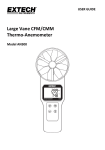
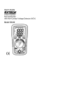
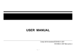
User's Manual 99 Washington Street Melrose, MA 02176 Phone 781-665-1400 Toll Free 1-800-517-8431 Visit us at www.TestEquipmentDepot.com CFM/CMM Thermo Anemometer + InfraRed Thermometer Model AN200 cf m/cmm Anemometer Thermometer AN200 UNITS NEXT AREA PROBE TEMPERATURE RECALL Introduction Congratulations on your purchase of the Extech AN200 CFM/CMM Thermo Anemometer with InfraRed Thermometer. This instrument measures Air Velocity, Air Flow (volume), Air Temperature (with probe) and Surface Temperature (with the InfraRed function). The large, easyto-read backlit LCD includes primary and secondary displays plus numerous status indicators. The InfraRed feature includes a laser pointer for convenient targeting. In addition, the meter can store 16 area setting dimension for easy recall. This meter is shipped fully tested and calibrated and with proper use will provide years of reliable service. Safety Use extreme caution when the laser pointer beam is on Do not point the beam toward anyone's eye or allow the beam to strike the eye from a reflective surface Do not use the laser near explosive gases or in other potentially explosive areas CAUTIONS Improper use of this meter can cause damage, shock, injury or death. Read and understand this user manual before operating the meter. Inspect the condition of the probe and the meter itself for any damage before operating the meter. Repair or replace any damage before use. If the equipment is used in a manner not specified by the manufacturer, the protection provided by the equipment may be impaired. This device is not a toy and must not reach children’s hands. It contains hazardous objects as well as small parts that the children could swallow. In case a child swallows any of them, please contact a physician immediately Do not leave batteries and packing material lying around unattended; they can be dangerous for children if they use them as toys In case the device is going to be unused for an extended period of time, remove the batteries to prevent them from draining Expired or damaged batteries can cause cauterization on contact with the skin. Always, therefore, use suitable hand gloves in such cases See that the batteries are not short-circuited. Do not throw batteries into the fire. Do not directly view or direct the laser pointer at an eye. Low power visible lasers do not normally present a hazard, but may present some potential for hazard if viewed directly for extended periods of time 2 AN200-EU-EN-V2.5-6/13 Meter Description 1. Power ON/OFF button 2. Probe input jack 3. Laser pointer 4. IR Sensor 5. Rubber holster 6. LCD Display 7. IR thermometer measurement button 8. Airflow buttons (4) 9. Air Temperature function buttons (2) 10. Vane 11. Airflow Average button 12. Backlight button 13. MAX‐MIN button for TEMPERATURE mode 14. HOLD for TEMPERTAURE functions 15. MAX‐MIN button for AIR VELOCITY/AIR FLOW (also used as left arrow button) 16. UNITS for AIR VELOCITY/AIR FLOW mode (also used as up arrow button) 17. HOLD for AIR VELOCITY/AIR FLOW mode (also used as right arrow button) 18. AREA button for AIR FLOW (Volume) mode See next section for additional keypad description information. Battery compartment is located on rear of instrument, rubber meter jacket must be removed to access battery compartment 3 AN200-EU-EN-V2.5-6/13 Keypad • Press to turn the meter ON or OFF • IR + Laser Pointer Press and hold to measure. • MAX/MIN (Airflow) Record and store the highest and lowest airflow or velocity readings. ◄ (LEFT) also serves as change decimal point button in AREA mode • UNITS Press to select the mode of operation. In FLOW mode, the meter displays air volume. In VELOCITY mode, the meter displays air speed. ▲ (UP) also serves as increase number button in AREA mode. • HOLD Press to freeze the displayed reading. Press again to unlock display. ►(RIGHT) also serves as change digit button in AREA mode. • AREA Press and hold to manually enter the area of a duct in CFM or CMM mode. Press and hold to scroll thru memory locations. This button also clears memory in the Averaging mode. • Press to turn the backlight on/off. Hold to disable Auto Power Off. • MAX/MIN (Temperature) temperature. • • Press to record and store the highest, lowest readings for air HOLD (Temperature) Press to freeze the displayed temperature reading. Press again to unlock the display. AVG Press and hold to enter averaging mode. Averages up to 20 readings. 4 AN200-EU-EN-V2.5-6/13 Display Layout MAX (top of LCD): Max Hold function engaged for the Air Temperature function HOLD (top of LCD): Data Hold function engaged for the Air Temperature function PROBE TEMP: Reminder that the top LCD digits represent Air (Vane) Temperature : Indicates that the laser pointer is on. IR TEMP: Indicates that the larger LCD digits represent IR temperature measurement VEL: indicates that meter is in air velocity mode FLOW: indicates that meter is in air flow mode MAX (bottom of LCD): Max Hold for the IR Temperature and RH function HOLD (bottom of LCD): Data Hold for the IR Temperature function and RH function o CFM/CMM: airflow units of measure Ft , m : units for area dimensions o C / F: Temperature units of measure 2 2 m/s, ft/min, km/h, MPH, knots: air velocity units of measure X10, X100: multipliers for air flow readings AVG: air averaging mode RECORD: indicates that min/max function is running (top for temp, bottom for air) Large LCD digits at center of display for Relative Humidity and IR Temperature Smaller LCD digits at top, right of display for Probe Temperature : Low battery indicator 5 AN200-EU-EN-V2.5-6/13 Operation Connecting the Vane 1. The vane plug is inserted in the meter’s sensor jack at the top of the meter. The plug and jack are keyed so that the plug can only fit in the jack one way. 2. Turn the plug carefully until it lines up with the jack and then firmly push the plug in place. Do not apply undue force or try to twist the plug side-to-side. 3. If the vane is not connected to the meter or if the sensor is defective, the LCD display will indicate dashed lines in place of an air velocity reading. Air Velocity Measurements 1. Turn on the meter using the Side view of Vane ON/OFF button. 2. Press UNITS button to select the desired unit of measure. NOTE: At power up the meter will display the last unit of measure previously entered. 3. Place the sensor in the air stream. Ensure that the air enters the vane as indicated by the arrow sticker placed inside the vane. Refer to the diagram. Arrow airflow 4. View the air velocity and temperature readings on the LCD Display. The large main LCD display shows the Air Velocity reading. The upper right LCD sub-display shows the temperature reading. Air Velocity Measurements (Up to 20 Point averaging) 1. To enter 20 Point Averaging Mode, press and hold the AVG button until it beeps twice. The AVG icon will be displayed. 2. Take a measurement and press the AVG button. A single beep will sound and the HOLD icon will appear in the display. 3. The average reading will be displayed and number of readings measured will appear in the upper right hand corner of the display. After 5 seconds, the display will return to the current reading. 4. Repeat steps 2 - 3 until all desired points have been measured. 5. To return to standard velocity measuring mode press and hold AVG button until meter beeps twice. Note: In the standard velocity measuring mode, press the AVG button once to recall the previous average. The average will be cleared when you enter the Averaging Mode again. 6 AN200-EU-EN-V2.5-6/13 Air Flow Measurements (CMM / CFM) 1. Turn on the meter using the 2. Press the UNITS button to select the desired air flow units: CMM (cubic meters per minute) or CFM (cubic feet per minute). NOTE: At power up the meter will display the last unit of measure previously entered. 3. 4. ON/OFF button 2 Side view of Vane Arrow 2 To begin entering the area in m or ft , press and hold the AREA button until it beeps twice. The leftmost digit of the bottom display will begin to flash. airflow Use the ▲ (UP) button to change the flashing digit Use the ◄ (LEFT) button to move the decimal Use ► (RIGHT) button to select the other digits. After all of the digits are entered, press and hold the AREA button (until meter beeps twice) to save the area into memory and return to CFM or CMM measuring mode. 5. Place the sensor in the air stream. Ensure that the air enters the vane as indicated by the arrow sticker placed inside the vane. Refer to the diagram. The large main LCD display shows the Air Velocity reading. The upper right LCD sub-display shows the temperature reading. The meter has 16 memory locations (8 for CFM and 8 for CMM) that can be used to store commonly used area sizes that you can recall at anytime. 1. Press the AREA button until meter beeps twice. A memory location number will appear in the top right of the display indicating the memory location. 2. Push the AREA button to scroll thru and select the desired location. Once you have selected the desired memory location enter your dimension Use the ▲ (UP) button to change the flashing digit Use the ◄ (LEFT) button to move the decimal Use ► (RIGHT) button to select the other digits. After all of the digits are entered, press and hold the AREA button (until it beeps twice) to save the area into memory and return to CFM or CMM measuring mode. To select and use a previously stored dimension, press and hold the AREA button until it beeps twice. Press AREA to scroll thru the 8 memory locations. Press and hold the AREA button until it beeps twice to return to the CFM or CMM measuring mode. Air Flow Measurements (Up to 20 Point averaging) 1. To enter 20 Point Averaging Mode, press and hold the AVG button until it beeps twice. The AVG icon will be displayed. 2. Take a measurement and press the AVG button. A single beep will sound and the HOLD icon will appear in the display. 3. The average reading will be displayed and number of readings measured will appear in the upper right hand corner of the display. After 5 seconds, the display will return to the current reading. (IMPORTANT: Please note that the average readings are only held for 5 seconds and cannot be recalled.) 4. Repeat steps 2 - 3 until all desired points have been measured. 5. Press the AREA button to clear the multipoint averaging memory. 6. To return to standard airflow measuring mode press and hold AVG button until meter beeps twice. 7 AN200-EU-EN-V2.5-6/13 Data Hold (Air Velocity/Air Flow) 1. While taking measurements, press the HOLD button to freeze the air velocity/air flow reading for later viewing. 2. The HOLD indicator will appear in the bottom of the LCD display. 3. Press HOLD again to return to normal operation. MAX/MIN/AVG Record (Air Velocity/Air Flow) This allows the user to record and view the highest (MAX), lowest (MIN) and average (AVG) readings. The AVG indicator and RECORD indicator along with 1. Press the Airflow MAX/MIN button. the average reading will appear on the LCD display and the meter will begin keeping track of the MAX, MIN and Average values. 2. Press the MAX/MIN button again. The MAX indicator will appear on the display and display the Max reading. 3. Press the MAX/MIN button again to view the minimum reading. The MIN indicator along with the minimum reading will appear on the LCD display and display the Min reading. 4. Press the MAX/MIN button again to display current readings. NOTE: the meter will keep recording MAX/MIN/AVG readings. 5. To clear and stop MAX/MIN/AVG recording and return to normal operation, press the AREA button once when displaying the current reading. Temperature Units 1. Remove the meter’s rubber protective jacket and select the desired temperature units using the °F/°C slide switch located in the battery compartment. 2. Replace the protective jacket and connect the sensor to the sensor input jack on top of the meter. Data Hold (Air Temperature) 1. While taking measurements, press the PROBE TEMPERATURE HOLD button to freeze the air temperature reading. 2. The HOLD indicator will appear in the bottom of the LCD display. 3. Press PROBE TEMPERATURE HOLD again to return to normal operation. Max/Min Record (Air Temperature) This allows the user to record and view the highest (MAX), lowest (MIN) air temperature readings. 1. Press the Temperature MAX/MIN button once. The MAX indicator will appear on the display and the meter will begin keeping track of the MAX/MIN air temperature values. 2. Press the button again to view the minimum reading. The MIN indicator along with the minimum air temperature reading will appear on the LCD display. 3. Press the button again to return to normal operation. Automatic Power OFF To conserve battery life, the meter automatically turns off after 20 minutes. To override this feature: 1. 2. 3. 4. 5. Turn the meter OFF. Press and hold the (Backlight) key while turning the meter ON. “dis APO” will appear in the display. The AUTO POWER OFF feature will now be disabled. Note that AUTO POWER OFF is re-enabled each time the meter is turned on. Also note that AUTO POWER OFF is disabled in CFM/CMM mode. 8 AN200-EU-EN-V2.5-6/13 InfraRed (Non-Contact) Temperature Measurements 1. The IR sensor is located at the top of the meter. 2. Point the sensor toward the surface to be measured. 3. Press and hold the red IR button to begin measuring the surface temperature of a desired target. IR TEMP and will appear on the display. The laser pointer will switch on to help aim the meter. 4. The measured IR surface temperature will appear at the center of the LCD (larger digits). The temperature displayed is the temperature of the area within the spot. 5. When the red IR button is released, the laser pointer will switch off and the reading will freeze (data hold) on the display for approximately 3 seconds. 6. Note that the vane (Air Temperature) continues to monitor temperature during IR tests and its temperature is displayed on the top of the LCD (smaller digits). 7. After approximately 3 seconds the meter defaults to the Air Flow and Air Temperature display. WARNING: Do not directly view or direct the laser pointer at an eye. Low power visible lasers do not normally present a hazard, but may present some potential for hazard if viewed directly for extended periods of time. Battery Replacement When appears on the LCD, the 9V battery must be replaced. 1. Disconnect the vane. 2. Remove the meter’s rubber protective jacket 3. Use a Phillips screwdriver to open the rear battery compartment 4. Replace the 9V battery 5. Close the battery compartment and replace the meter’s protective jacket You, as the end user, are legally bound (EU Battery ordinance) to return all usedbatteries, disposal in the household garbage is prohibited! You can hand over your used batteries / accumulators at collection points in your community or wherever batteries / accumulators are sold! Disposal: Follow the valid legal stipulations in respect of the disposal of the device at the end of its lifecycle 9 AN200-EU-EN-V2.5-6/13 Specifications Air Velocity Range Resolution Accuracy m/s (meters per sec) 0.40 - 30.00 m/s 0.01 m/s ± (3%rdg + 0.20 m/s) km/h (kilometers/hour) 1.4 - 108.0 km/h 0.1 km/h ± (3%rdg + 0.8 km/hr) ft/min (feet per minute) 80 – 5900 ft/min 1 ft/min ± (3%rdg + 40 ft/m) mph (miles per hour) 0.9 – 67.0 mph 0.1 mph ± (3%rdg + 0.4 MPH) knots (nautical MPH) 0.8 to 58.0 knots 0.1 knots ± (3%rdg + 0.4 knots) Range Resolution Area 0.1 0 to 999.9m Air Flow CMM (cubic meters/min) CFM (cubic ft/min) Air Temperature 3 0-999999 m /min 3 0-999999 ft /min Range o InfraRed Temperature 0.1 o 0 to 999.9ft 2 2 Resolution Accuracy o 4.0 F (2.0 C) o o 14 - 140 F (-10 - 60 C) 0.1 F/C Range Resolution Accuracy o ±9.0 F (5.0 C) 1 F/C ±2% reading or ±4 F o (2 C) whichever is greater o o -58 to -4 F (-50 to -20 C) o o -4 to 500 F (-20 to 260 C) 0.1 F/C o o o o Circuit Display Sampling rate Custom LSI microprocessor circuit Dual function 13 mm (0.5") 4-digit LCD 1 reading per second approx. Sensors Air velocity/flow sensor: Conventional angled vane arms with low-friction ball bearing. Temperature sensors: NTC-type precision thermistor and InfraRed 6 to 14µm 0.95 fixed 8:1 2.5 readings per second approx. Auto shut off after 20 minutes to preserve battery life 0°C to 50°C (32°F to 122°F) o o -10 to 60 C (14 to 140 F) <80% RH <80% RH 2000 meters (7000ft) maximum One 9 volt (NEDA 1604) battery IR Spectral response IR Emissivity IR distance ratio IR sampling rate Automatic Power off Operating Temperature Storage Temperature Operating Humidity Storage Humidity Operating Altitude Battery Battery life Battery current Weight Dimensions 80 hours approx. (if Backlight and Laser are used continuously the battery life is reduced to 2 to 3 hours approx.) 8.3 mA DC approx. 725g (1.6 lbs) including battery & probe Main instrument: 178 x 74 x 33mm (7.0 x 2.9 x1.2") Sensor Head: 70mm (2.75”) Diameter 10 AN200-EU-EN-V2.5-6/13 InfraRed Measurement Considerations When taking IR measurements the meter automatically compensates for ambient temperature changes. Note that it may take up to 30 minutes to adjust to extremely wide ambient changes. Low temperature measurements quickly followed by high temperature measurements may require several minutes to stabilize as a result of the IR sensor cooling process. If the surface of the object under test is covered with frost, oil, grime, etc., clean before taking measurements. If an object's surface is highly reflective apply masking tape or flat black paint before measuring. Steam, dust, smoke, etc. can obstruct measurements. To find a hot spot, aim the meter outside the area of interest then scan across (in an up and down motion) until the hot spot is located. IR Theory IR thermometers measure the surface temperature of an object. The meter’s optics sense emitted, reflected, & transmitted energy that is collected and focused onto the meter’s detector. The meter’s circuitry translates this information into an LCD reading. IR Field of View Ensure that the desired target is larger than the spot size as shown in the diagram below. As the distance from an object increases, the spot size of the area measured by the meter becomes larger. The meter’s field of view ratio is 8:1, meaning that if the meter is 8 inches from the target, the diameter (spot) of the object under test must be at least 1 inch. Other distances are shown below in the field of view diagram. Emissivity Most organic materials and painted or oxidized surfaces have an emissivity of 0.95. Inaccurate readings will result when measuring shiny or polished surfaces. To compensate, cover the surface under test with masking tape or flat black paint. Allow time for the tape to reach the same temperature as the material underneath then measure the temperature of the tape or the painted surface. 11 AN200-EU-EN-V2.5-6/13 Thermal Emissivity Table for Common Materials Material Emissivity Material Emissivity Asphalt 0.90 to 0.98 Cloth (black) 0.98 Concrete 0.94 Human skin 0.98 Cement 0.96 Leather 0.75 to 0.80 Sand 0.90 Charcoal (powder) 0.96 Earth 0.92 to 0.96 Lacquer 0.80 to 0.95 Water 0.67 Lacquer (matt) 0.97 Ice 0.96 to 0.98 Rubber (black) 0.94 Snow 0.9 Plastic 0.85 to 0.95 Glass 0.85 to 1.00 Timber 0.90 Ceramic 0.90 to 0.94 Paper 0.70 to 0.94 Marble 0.94 Chromium oxides 0.81 Plaster 0.80 to 0.90 Copper Oxides 0.78 Mortar 0.89 to 0.91 Iron Oxides 0.78 to 0.82 Brick 0.93 to 0.96 Textiles 0.90 12 AN200-EU-EN-V2.5-6/13 Useful Equations and Conversions Area equation for rectangular or square ducts Height (H) Area (A) = Width (W) x Height (H) Width (W) Area equation for circular ducts Area (A) = x r2 Where = 3.14 and r2 = radius x radius Radius Cubic equations CFM (ft3/min) = Air Velocity (ft/min) x Area (ft2) CMM (m3/min) = Air Velocity (m/sec) x Area (m2) x 60 NOTE: Measurements made in inches must be converted to feet or meters before using the above formulae. Unit of Measure Conversion Table m/s ft/min knots km/h MPH 1 196.87 1.944 3.6 2.24 1 ft/min 0.00508 1 0.00987 0.01829 0.01138 1 knot 0.5144 101.27 1 1.8519 1.1523 1 km/h 0.2778 54.69 0.54 1 0.6222 1 MPH 0.4464 87.89 0.8679 1.6071 1 1 m/s 13 AN200-EU-EN-V2.5-6/13