1
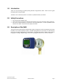
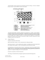
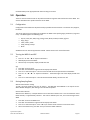
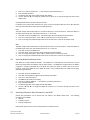
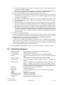
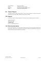
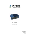
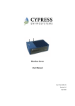
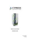
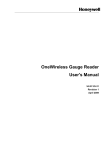
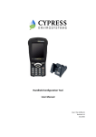
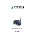
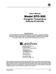
Wireless Gauge Reader
User Manual
Doc # 152-10101-01
Revision 1.2
May 2009
Copyrights
Copyright 2008 by Cypress Envirosystems. All rights reserved.
The information in this document is subject to change without notice. While reasonable precautions have been
taken, Cypress Envirosystems assumes no responsibility for any errors that may appear in this document. No part
of this document may be copied or reproduced in any form or by any means without the prior written consent of
Cypress Envirosystems.
Disclaimer
CYPRESS ENVIROSYSTEMS MAKES NO WARRANTY OF ANY KIND, EXPRESS OR IMPLIED, WITH REGARD TO THIS
MATERIAL, INCLUDING, BUT NOT LIMITED TO, THE IMPLIED WARRANTIES OF MERCHANTABILITY AND FITNESS FOR
A PARTICULAR PURPOSE. Cypress Envirosystems reserves the right to make changes without further notice to the
materials described herein. Cypress Envirosystems does not assume any liability arising out of the application or
use of any product or information described herein. Cypress Envirosystems does not authorize its products for use
in mission or safety critical systems or where a malfunction or failure may reasonably be expected to result in
significant injury to the user. The inclusion of Cypress Envirosystems’ product in mission or safety critical system
applications implies that the manufacturer assumes all risk of such use and in doing so indemnifies Cypress
Envirosystems against all charges. In no event is Cypress Envirosystems liable to anyone for any indirect, special or
consequential damages.
Table of Contents
1.0
2.0
3.0
4.0
5.0
6.0
7.0
8.0
9.0
10.0
11.0
Introduction ........................................................................................................................ 4
Safety Precautions .............................................................................................................. 4
Description of the WGR ...................................................................................................... 4
3.1
Sample Collection ................................................................................................... 5
3.2
Cypress Envirosystems Monitoring System............................................................ 6
3.3
Related Products..................................................................................................... 6
3.4
WGR LCD Menu Flow Chart .................................................................................... 7
Setup ................................................................................................................................... 8
4.1
Components............................................................................................................ 8
4.2
Installation Overview .............................................................................................. 8
Operation .......................................................................................................................... 10
5.1
Configuration ........................................................................................................ 10
5.2
Turning the WGR On and Off................................................................................ 10
5.3
Setting Sampling Rates ......................................................................................... 10
5.4
Accessing Node Identification Data ...................................................................... 11
5.5
Accessing Informative Data Parameters in the WGR ........................................... 11
5.6
Configuration and Setup Menus........................................................................... 12
Care and Maintenance...................................................................................................... 12
6.1
Calibration............................................................................................................. 12
6.2
Battery Life............................................................................................................ 12
Troubleshooting................................................................................................................ 12
Technical Specifications .................................................................................................... 13
Product Disposal ............................................................................................................... 14
Support.............................................................................................................................. 14
Warranty Information....................................................................................................... 14
1.0 Introduction
Thank you for purchasing the patent-pending Wireless Gauge Reader, WGR. Please read this guide
thoroughly before using the WGR.
The WGR is not a stand-alone product. See Section 3.3, Related Products, for details.
2.0 Safety Precautions
•
•
•
Do not immerse the WGR in water.
Always wear personal protective equipment appropriate to the system the WGR is being installed on.
Do not try to repair yourself as it contains no user-serviceable parts. Contact a qualified service
technician for repairs. See Section 10.0, Support, for details.
3.0 Description of the WGR
The Cypress Envirosystems Wireless Gauge Reader, WGR, is designed to read manual gauges and transmit
the data to a PC or data acquisition system. The WGR is designed to be non-invasive. It is attached over
the face of an existing analog gauge, as shown below. Each WGR comes with an adapter that is sized for
the gauge it is reading. Adapters range in size to fit over gauge faces that are 1.5” to 4.6” in diameter.
WGR display
Cypress Envirosystems
Doc # 152-10101-01 Rev 1.2
WGR User Manual
Page 4
The WGR optically reads the gauge face and wirelessly transmits the reading. This value is displayed
locally on the LCD. A representation of the LCD is shown below.
The battery operated WGR is specifically configured to the gauge that it is reading. During installation,
the WGR is positioned per the owner specifications. The WGR can be positioned at an offset to the gauge.
For example, a gauge could be mounted sideways on a system, but the WGR could be positioned upright
for easier reading. Once the WGR is in position, it is secured in place for calibration. The range of the
gauge, units of measure, and any offsets are entered into the WGR. The WGR is calibrated by a trained
installation technician, and ready for use.
3.1
Sample Collection
Samples are collected one of three ways.
Manual instantaneous reading. The user can physically take a reading at the WGR.
Routine data collection. A routine sampling interval between 1 and 65000 seconds can be programmed
into the WGR. When the WGR is on, this is the sampling interval that data will be collected.
Pre-programmed short term data collection intervals. Each WGR comes with two pre-programmed data
collection intervals. These are short term intervals of data collection that override the routine data
collection rate. They are intended to be used for troubleshooting, or during known events when the user
might want to change the sampling rate for a short period of time.
See Section 5.0, Operation, for detailed instructions.
The reading is transmitted wirelessly through the Cypress Envirosystems Monitoring System.
Cypress Envirosystems
Doc # 152-10101-01 Rev 1.2
WGR User Manual
Page 5
3.2
Cypress Envirosystems Monitoring System
The Cypress Envirosystems Wireless Gauge Reader is part of the Cypress Envirosystems Monitoring
System. This system can be setup one of two ways:
3.3
Related Products
The WGR sends data to the Cypress Envirosystems Blue Box Server, which stores the data in a SQL server.
The WGR can communicate directly to the Blue Box Server, or through Wireless Range Extenders.
Wireless Gauge Reader
(WGR)
Blue Box Server
(BBS)
Wireless Range Extender
(WRE)
Cypress Envirosystems
Doc # 152-10101-01 Rev 1.2
WGR User Manual
Page 6
3.4
WGR LCD Menu Flow Chart
The following flow chart displays all the menu options.
Normal Sample Mode
105 3
.
PSI
Exit
Fast Sample Mode
Exit to Sample Menu
Normal
Sample
Mode
FAST
Exit
Medium Sample Mode
MED
Enter
Fast Sample Mode
105 3
.
PSI*
Exit to Sample Menu
Normal
Sample
Mode
Enter
Exit
Image Capture Mode
DATA
CONF
G
Enter
Enter*
Medium Sample Mode
Exit
Setup Menu
SETU
P
Restricted
Image Capture Mode
105 3
.
Exit
PSIm
Node ID
Exit
Normal Update Rate
255
Exit to Sample Menu
Normal
Sample
Mode
300
NODE
UPDT
E
255
300
Edit*
• Fast Sample Mode:
Every 5 Seconds for 5-Minutes.
• Medium Sample Mode:
Every 30 Seconds for 8-Hours.
Edit*
NODE
?
Exit
Temperature - Celsius
27
DEG C
Restricted
Exit
WGR Firmware Version
01.08.1
VER
Restricted
ConF
1E4C3
Exit to
Normal
Sample
Mode
UPDTE?
*Requires Password
Up
Cypress Envirosystems
Doc # 152-10101-01 Rev 1.2
Exit
Data Display
Accept Down
Up
Accept Down
WGR User Manual
Page 7
4.0 Setup
4.1
Components
The WGR comes with the following components:
WGR
Adapter
Clamp
Note: The WGR may come attached to the adapter, or separate, as defined by the part number.
Ensure the adapter is correctly sized for the gauge face. Custom adapters are shipped with WGRs, based
on the gauge information provided at the time of purchase.
4.2
Installation Overview
Step 1. Verify gauge functionality
1. Ensure that there are no blockages between WGR and gauge face (stickers, marks, etc.).
2. Use an appropriate cleaning agent, such as isopropyl alcohol to clean the gauge face Also, make sure
there are no deep scratches on the gauge window.
3. For liquid filled gauges, please make sure the gauge is filled completely.
Clean Gauge
Dirty Gauges
Step 2. Verify WGR functionality
Turn on the WGR if it is in deep sleep (if the display is off).
1. Press “●” “●” “►” “◄” “●” sequence of buttons in succession, within 5 seconds.
2. The WGR display should say BOOT.
3. Once boot-up is complete, display should show 0.0 along with the ERROR icon.
Check functionality of the WGR.
1. Press “●” to take a reading.
2. A red light at the back of the WGR should flash, and the SAMPLE icon on the LCD will briefly flash.
3. The display will still most likely indicate an error (small ERROR icon), since the WGR has not yet been
calibrated for a gauge. This is normal behavior.
Cypress Envirosystems
Doc # 152-10101-01 Rev 1.2
WGR User Manual
Page 8
Step 3. Mounting the WGR
1. For a panel mounted gauge, you must first adhere a panel mount adapter to the panel.
a. Ensure that the WGR mounting adapter and the panel mount adapter are the proper size for the
gauge.
b. Clean the panel surface with isopropyl alcohol to ensure there is no dirt or oil that would prevent
good adhesion.
c. Remove the backing from the Dual-Lock ring on the panel mount adapter.
i. Make sure that both sides of the dual-lock rings are still fastened to the adapter, for easier
installation.
ii. Do not peel the Dual-Lock ring off of the adapter and attempt to install it separately from
the panel mount adapter.
d. Carefully line up the panel mount adapter centered around the gauge, and press it onto the
panel for several seconds applying pressure to create a good bond.
e. If required, the adapter can be removed from the panel by separating the Dual-Lock material, but
it is better to avoid this since it may weaken the VHB adhesive bond, and may weaken the DualLock bond.
2. Ensure that the proper size mounting adapter is fastened to the WGR main housing by holding it up
to the gauge or panel mount adapter collar.
a. Loosen the clamp to make sure it is not prematurely compressing the adapter mounting fingers
b. Determine if silicone bands or “shims” will be required for the adapter to properly grasp the
gauge.
i. No silicone bands should be used when fastening to a panel mount adapter.
ii. Better adhesion is obtained if at least one thin silicone band is used to mount to a free
standing gauge.
iii. Some gauges have a very narrow lip around their face, and it is helpful to build up 1-2
silicone bands next to the lip to give the WGR adapter a wider surface to grasp securely.
c. The fingers of the adapter should not have to flex outward very far in order to fit around the
gauge, since this configuration is not very secure.
i. Select a larger adapter, if this is the case.
3. Using the adapter, place the WGR over the analog gauge or panel mount adapter.
a. The adapter should be slid onto the gauge at least 1cm (3/8 in) past the front face of the gauge
to ensure a secure grasp around the circumference of the gauge body.
b. If using a panel mount adapter, the mounting adapter should be slid completely onto the panel
mount adapter collar.
c. Position the WGR as desired, typically with the LCD oriented perfectly horizontal for easy human
readability.
d. The WGR does not need to be directly aligned with the direction of the gauge. For example, a
gauge that is mounted sideways can have a WGR mounted vertically so that the LCD display can
be read easily.
WGR being placed on gauge that is facing sideways
4.
Tighten the clamp around adapter to secure the WGR to the gauge or panel mount adapter.
a. The clamp should be even with the edge of the adapter for optimal performance.
b. Be careful not to over tighten the clamp.
c. Ensure that the WGR is securely mounted before proceeding to the next step.
Cypress Envirosystems
Doc # 152-10101-01 Rev 1.2
WGR User Manual
Page 9
CAUTION: Always wear appropriate PPE when working on live lines.
5.0 Operation
There are various functions that can be performed both through the web interface and at the WGR. This
section describes how to perform functions at the WGR.
5.1
Configuration
Configuration of the WGR must be performed by a qualified service technician. See Section 10.0, Support,
for details.
The service technician will configure and calibrate the WGR to the specific gauge parameters (range and
units). The WGR supports the following units.
•
•
•
•
•
PSI, bar, mbar, kPa, MPa, inHg, mmHg, inH2O, ftH2O, cmH2O, mmH2O, kg/cm2
Deg F, Deg C
Volts, mVolts, uVolts
Amps, mAmps, uAmps
Blank
Additional units can also be supported as needed. Please contact us for more information.
5.2
Turning the WGR On and Off
On
1. Press “●” “●” “►” “◄”“●” sequence of buttons.
2. WGR display should read BOOT.
3. Once boot-up is complete, display should show 0.0.
Off
1.
2.
3.
4.
5.
5.3
Press “►” to access menu.
Press “►” until the bottom right side of the display reads SETUP.
Press “●” to select this option. The next screen should ask for the password and read PSWD?.
Press “●” “●” “►” “◄” “●” sequence of buttons. The bottom right side of the display should read
SHIP.
Press “●” to select this option. The LCD should read SHIP briefly, and then turn off.
Setting Sampling Rates
Manual instantaneous reading
To take a one-time reading, press the “●” button. The WGR will show SAMPLE in the top left corner.
When SAMPLE disappears, the reading on the LCD will be updated.
Routine data collection
Whenever the WGR is on, it samples based on the routine data collection rate. This rate is between 0 and
65535 seconds, or approximately 18 hours. This value is defined by the user, and can be changed at the
WGR.
1.
2.
3.
4.
Press “►” to access the WGR menu.
Press “►” until the bottom right side of the display reads DATA.
Press “●” to select this option. Press “◄” if you need to cancel and return to the main screen.
Once in the DATA menu, press “►” until you reach the UPDTE submenu.
Cypress Envirosystems
Doc # 152-10101-01 Rev 1.2
WGR User Manual
Page 10
5.
6.
7.
8.
Press “●” to edit the update rate. ** This feature is password protected. **
Enter the WGR password.
The bottom right side of the display should read UPDTE?
Use the “◄” and “►” to change the update rate and press “●” to save the change and return to the
UPDTE menu.
Preprogrammed short term data collection intervals.
In addition to the routine data collection rate, there are two pre-programmed short term data collection
intervals associated with the WGR, FAST and MED (medium).
FAST
The FAST sample mode collects data at a 5-second interval for a 5-minute duration. While the WGR is in
the FAST sample mode, the units of data will have an “*” at the end.
1. Press “►” to access the WGR menu. The bottom right side of the display should read FAST.
2. Press “●” to select this option. Press “◄” to cancel and return to the main screen.
3. Press “●” during the modified sample mode to cancel and return to the normal sample mode.
MED
The MED sample mode collects data at a 30-second interval for an 8-hour duration. While the WGR is in
the MED sample mode, the units of data will have an “m” at the end.
1. Press “►” to access the WGR menu.
2. Press “►” again. The bottom right side of the display should read MED.
3. Press “●” to select this option. Press “◄” to cancel and return to the main screen.
4. Press “●” during the modified sample mode to cancel and return to the normal sample mode.
5.4
Accessing Node Identification Data
Each WGR has a unique NODE ID identifier. This NODE ID is a value between 0 and 255 and is used to
identify the data within the database and the web interface. The NODE ID is assigned when the WGR is
configured. Changing the NODE ID at the WGR will impact the ability to collect data at the server.
However, viewing the NODE ID of the WGR will make it easy to differentiate one WGR from another,
should they get mixed up.
1.
2.
3.
4.
5.
6.
7.
8.
5.5
Press “►” to access the WGR menu.
Press “►” until the bottom right side of the display reads DATA.
Press “●” to select this option.
The NODE ID will show on the display.
Press “●” to edit the NODE ID. ** This feature is password protected. **
Enter the WGR password.
The bottom right side of the display should read NODE?
Use the “◄” and “►” to change the NODE ID and press “●” to save the change and return to the
NODE menu.
Accessing Informative Data Parameters in the WGR
Several data parameters can be viewed, but not edited in the WGR’s DATA menu. The following
parameters are available:
1. Node ID
2. Firmware Version
3. Internal Temperature
Follow these steps in order to access the parameters in the DATA menu:
Cypress Envirosystems
Doc # 152-10101-01 Rev 1.2
WGR User Manual
Page 11
1.
2.
3.
4.
5.
6.
5.6
Press “►” to access the WGR menu.
Press “►” until the bottom right side of the display reads DATA.
Press “●” to select this option.
Press “►” to scroll through different data parameters until you reach VER.
The firmware version of the WGR will show on the display.
Press “◄” to exit the menu and return to the normal operating display screen, or if no button is
pressed for 10 seconds, the WGR will automatically return to the normal operating display screen.
Configuration and Setup Menus
The CONFG and SETUP menus are primarily restricted and for use by qualified service technicians to
configure and install the WGR. With the exception of turning off the WGR, both menus are access
restricted.
6.0 Care and Maintenance
6.1
Calibration
Calibration is performed when WGR is configured during installation. Calibration is performed based on
the position of the WGR with respect to the gauge face.
Re-calibration not required if the WGR is not removed from gauge or the position of the WGR with
respect to the gauge face is not shifted.
If the WGR is removed from gauge face, contact a service technician to re-calibrate the WGR. Simply
repositioning the WGR on the gauge may result in erroneous readings. See Section 10.0, Support, for
contact information.
6.2
Battery Life
Each WGR comes with two lithium batteries. Battery status can be monitored on the LCD of the WGR, or
through the user interface connected to the Blue Box Server. Battery change-out must be performed by a
qualified service technician. See Section 10.0, Support, for contact information.
The battery life of the WGR is dependent on the sampling frequency. Typical ranges are listed below.
Sampling Frequency
1 sample per 5 minutes
1 sample per 15 minutes
1 sample per hour
1 sample per day
Estimated Battery Life
1 year
2 years
3 years
3.5 years
7.0 Troubleshooting
The WGR will not turn on.
Please contact a qualified service technician. See Section 10.0, Support, for contact information.
The WGR display shows ERROR in the upper left corner.
The ERROR message appears on the LCD when the WGR is having a problem obtaining a reading from the
gauge. Common causes for this are:
i)
The WGR has been moved from its configured position.
Cypress Envirosystems
Doc # 152-10101-01 Rev 1.2
WGR User Manual
Page 12
(1) If you think the WGR has been moved or knocked out of place, contact a qualified service
technician to re-calibrate the WGR.
(2) If the WGR is installed on equipment that is prone to vibration, the WGR may have slipped out of
place. Contact a qualified service technician to re-secure and re-calibrate the WGR.
ii) There WGR is having difficulty reading the gauge due to obstruction or vibration
(1) If the gauge is installed outdoors, condensate buildup inside the gauge itself may impact the
WGR from obtaining a good reading. If possible, install a liquid-filled gauge and have the WGR
re-installed and re-calibrated.
(2) If the gauge has multiple needles, the WGR may have an issue identifying which needle to read.
Try to install a gauge with only one needle. This issue should be raised by the service technician
during installation.
(3) If the gauge only has one needle, but there is nothing to distinguish one end of the needle from
the other, the WGR may have problems obtaining a reading. If possible, install a gauge that has a
different type of pointer. This issue should be raised by the service technician during installation.
(4) If the equipment that the gauge is monitoring causes the gauge needle to vibrate very rapidly
(such as some compressors), then the WGR may have difficulty capturing a clean reading from
the gauge. In this case, please replace the gauge with a dampened or liquid-filled gauge to slow
the motion of the needle. Then have the WGR re-installed and re-calibrated by a qualified
service technician.
iii) The pointer of the gauge has broken.
In some cases, gauges that are installed on equipment that are prone to vibration can break needles.
If you suspect this is the problem, contact a qualified service technician. If you remove the WGR
yourself to determine if this is the issue, you will still need to have the WGR re-calibrated.
iv) The wireless connectivity of the WGR to the server is weak.
In some cases, the wireless signal strength of a WGR to the server is affected by facility changes.
Weak connectivity from the WGR to the server will cause an error message. The ERROR message
should also be associated with a missing ANTENNA icon in the lower right hand corner of the LCD.
Contact a qualified service technician if this problem occurs.
If you have additional problems, please contact us. See Section 10.0, Support, for contact information.
8.0 Technical Specifications
Gauge Compatibility
Gauge Mounting
Data Capture Rate
Accuracy
Wireless Frequency
Wireless Range
Wireless Protocol
Approvals
Power Supply
Battery Life
Vibration
Humidity
Operating Temperature
Storage Temperature
Enclosure
Cypress Envirosystems
Doc # 152-10101-01 Rev 1.2
Most gauges from 1.5" to 4.64" (38mm to 114mm) diameter
Adapters with removable clamps
User-configurable: 1 sample per 5 seconds to 1 sample per 18 hours
± 1.5% of full scale gauge reader (e.g. ± 1.5 psi for 0 to 100 psi pressure
gauge)
2.4GHz Direct Sequence Spread Spectrum, 50mW peak output
Up to 1150 ft (350 m), high interference immunity, extendable with
repeaters
Cypress Semiconductor's highly optimized industrial DSSS radio and
protocol. Integrates robust security, antenna and frequency diversity,
optional encryption and minimal interference with existing wireless systems
(for additional details, please see FAQ at www.cypressenvirosystems.com)
FCC Class B compliant, RoHS, ETSI compliant
Two 3V lithium batteries
>1 year @ 1 sample per 5 min, >3 years at 1 sample/hour (approximate)
Up to 4G rms
10-99%RH, non-condensing
-4°F to 158°F (-20°C to 70°C)
-40°F to 176°F (-40°C to 80°C)
IEC IP66 compliant (outdoor, water resistant)
WGR User Manual
Page 13
Housing Material
Display
Dimensions
Weight
ABS with UV inhibitors
LCD display (for manual reading)
2.6” x 2.6” x 1.3” (65mm x 65mm x 33mm)
0.33lbs (150g) including batteries
9.0 Product Disposal
The WGR is recycled by Cypress Envirosystems. Contact a service technician or Cypress Envirosystems
headquarters to recycle the WGR. See Section 10.0, Support, for details.
10.0 Support
For additional support, including configuration, maintenance, and troubleshooting, please contact us.
Cypress Envirosystems
198 Champion Court
San Jose, CA 95134
+1 888 987 3210
Email: [email protected]
11.0 Warranty Information
Every product comes with a full one-year parts and labor warranty. Cypress Envirosystems monitoring of
battery status, product status, and potential communications packets are included during this period, so
that proactive service can be provided to our customers.
Cypress Envirosystems
Doc # 152-10101-01 Rev 1.2
WGR User Manual
Page 14