1
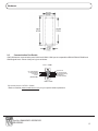
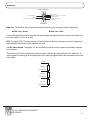
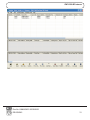
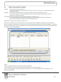
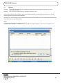
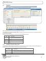
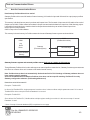
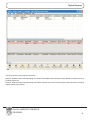
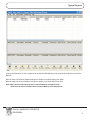
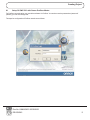
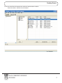
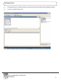
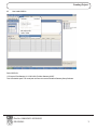
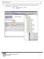
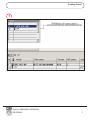
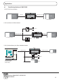
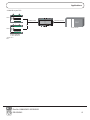
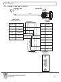
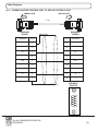
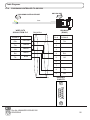
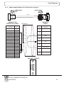
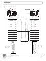
GWY-500
(Profibus Gateway)
USER’S MANUAL
COPYRIGHT NOTICE
This manual is a publication of Renu Electronics Pvt. Ltd. and is provided for use by its customers only.
The contents of the manual are copyrighted by Renu Electronics Pvt. Ltd.; reproduction in whole or in part, for use other
than in support of Renu Electronics Pvt. Ltd. equipment, is prohibited without the specific written permission of Renu
Electronics Pvt. Ltd..
SERVICE
If service is required then pack the unit in its original packaging container or, if unavailable, any suitable rigid container.
If a substitute container is used, surround the unit with shock absorbing material; damage in shipment is not covered
by the warranty. Include a letter with the unit describing the difficulty and Hardware Revision and Software Version.
Send to the following address:
Renu Electronics Pvt. Ltd.
Survey No. 2/6,
Baner Road,
Pune-411045
India
All returns will be tested to verify customer claims of noncompliance with the product warranty. Improper return
packaging, which makes verification impossible, will void the warranty. If noncompliance is verified and is not due to
customer abuse or the other exceptions described with product warranty,Renu Electronics Pvt. Ltd. will, at its option,
repair or replace the Product returned to it, freight prepaid, which fail to comply with the foregoing warranty, provided
Renu Electronics Pvt. Ltd. is notified of such noncompliance within the one-year warranty period.
ASSISTANCE
This manual is designed to provide the necessary information for trouble-free installation and operation of your new
Gateway product. However, if you need assistance, please call Renu Electronics Pvt. Ltd. at 91-20-27292840 or visit
our web site at www.renuelectronics.com
MANUAL REVISION
If you contact us in refference to this manual, please include the following document number
Name
:
Profibus Gateway (GWY-500-B) User’s Manual
Part Number
:
URML204
Document
:
UMAN\GWY-500-B\0106
Revision
:
Revision 5
Revision Number
Date
Description
Preliminary
Revision 0
Revision 1
10/11/2005
19/01/2006
17/03/2006
Revision 2
14/02/2007
Revision 3
08/10/2007
Revision 4
Revision 5
02/08/2010
12/12/2011
First Release
GSD file location is specified.
GSD file location is specified. GSD file model name is changed.
Communication and IBM cable details are added.
GWY-500 features (Default Communication Register, Recipes , Control
word for IDB,diagnostic Information) added. Cable details for thomson
controller, optomux, ABDF1, Hostlink & yokogawa are added.
Setup of Profibus Option Card with Siemens Profibus Master is revised.
(Section 8.2)
NS to GWY-500 cable connections are revised.
System requirement for gateway setup software revised
Warranty Certificate
For New product: This product is warranted against defects in materials and workmanship for a period of 12 months
from the date of shipment to Buyer.
For Rectified Products: Any product that will be replaced will have Warranty for 6 months or upto Original Product
Warranty period whichever is greater.
The warranty is limited to repair or replacement of the defective unit at the option of the manufacturer. This warranty is
void if the product has been altered, misused, dismantled, or otherwise abused.
ALL OTHER WARRANTIES, EXPRESSED OR IMPLIED, ARE EXCLUDED, INCLUDING BUT NOT LIMITED TO THE
IMPLIED WARRANTIES OF MERCHANTABILITY AND FITNESS FOR A PARTICULAR PURPOSE.
MAINTENANCE & SERVICE : There are no parts that can be serviced by the user. Service should be performed on a
unit substitution basis only. Do not attempt to remove, replace or service any printed circuit board, components or any
hardware/software related with display product. If problem within the display product occurs, contact the factory for
service information or repair.
NOTE : Renu Electronics Pvt. Ltd. is dedicated to providing complete customer service and customer satisfaction. If you
have any comments or criticisms about how to improve the product features/reliability, Please make a note of the
problem/improvement and notify us. We are always open to new ideas and improvements. So please let us know your
ideas and comments.
IMPORTANT
Gateway Products are intended to be Protocol Converters/Data Sharer devices
that can also take control actions on request of device being connected. It is assumed that
user is well acquainted with the PLC / Inverters / Controllers being used.
Any Mechanical or Electrical Modification to this Unit will
void all Warranties.
Contents
INTRODUCTION
1.1
1.2
1.3
Purpose of this manual
Introduction to Gateway
GWY-500 Specifications
HARDWARE
2.1
2.2
2.3
Introduction To Profibus
Protocol Architecture
Device Types
PROFIBUS-DP Characteristics
Bus Access Protocol
Data Throughput
Diagnostic Functions
Protection Mechanism
Network States
Device Data Base Files
Profiles
Introduction To GWY-500
GWY-500 Configuration
Configuration of GWY-500 (IBM Download)
When GWY-500 can accept configuration?
GWY-500-B FEATURES
4.1
4.1.1
4.1.2
4.2
4.3
4.4
4.5
4.6
4.7
4.8
4.9
4.10
Gateway Modes
Master-Master Configuration
Master-Slave Configuration
Repeat Cycle
Control Word
Error Indication Bit
Communication Parameters
Default Communication Register
Recipes
Control word for IDB
Diagnostic
Profibus Connection Status word
NOTE ON COMMUNICATION DRIVERS
5.1
Note On Communication Drivers
TYPICAL PROJECTS
6.1
6.2
6.3
6.4
Project Setup
Connect Toshiba Inverter as Profibus DPV0 Slave on Profibus Network with GWY-500
Connect Modicon PLC or other Modbus Slave devices as Profibus DPV0 Slave on
Profibus Network with GWY-500-B
Connect SCADA Software on Profibus Network
CONFIGURATION SOFTWARE
7.1
7.2
7
7
9
10
Dimensional details And Mounting Instructions
Communication Port Details
LED Status
GETTING STARTED
3.1
3.1.1
3.1.2
3.1.3
3.1.3.1
3.1.3.2
3.1.3.3
3.1.3.4
3.1.3.5
3.1.4
3.1.5
3.2
3.3
3.4
3.4.1
6
System Requirements
Installation Instruction
11
12
15
17
18
18
19
20
20
21
21
21
22
22
23
23
24
24
25
26
27
27
30
33
33
34
34
35
36
37
38
38
39
40
44
45
46
48
50
52
53
53
PROFIBUS MASTER SETUP
8.1
8.2
Setup Of GWY-500 with Omron Profibus Master
Setup Of GWY-500 with Siemens Profibus Master
APPLICATIONS
9.1
Possible Applications of GWY-500-B
CABLE DIAGRAMS
10.1
10.1.1
10.1.2
10.1.3
10.1.4
10.1.5
10.1.6
10.1.7
10.1.8
10.1.9
10.1.11
10.1.10
10.1.12
10.1.13
10.2
10.2.1
Communication Cables
TOSHIBA VF-S11 TO GWY-500
TOSHIBA T1 LINK PORT TO GWY-500
OMRON MASTER PROFIBUS PORT TO GWY-500 PROFIBUS PORT
SIEMENS MASTER PROFIBUS PORT TO GWY-500 PROFIBUS PORT
NS TO GWY-500
THOMSON TECHNOLOGY CONTROLLER TO GWY-500
OPTOMUX TO GWY-500
YOKOGAWA CONTROLLER TO GWY-500
AB SLC DH485 PORT TO GWY-500 (EC-P-007-00)
A B SLC DF1 PORT TO GWY-500 (EC-P-027B-00)
AB MICROLOGIX SERIES PLCs TO GWY-500 (EC-P-027A-00)
OMRON CQM1 PLC TO GWY-500 (EC-P-006B-00)
OMRON CQM/CPM CMOS PORT TO GWY-500 (EC-P-006A-00)
IBM Cables
IBM CABLE FOR GWY-500
54
55
69
81
82
84
85
85
86
87
88
89
90
91
92
92
94
95
97
97
98
98
Introduction
INTRODUCTION
In this chapter. . . .
♦
Purpose of this manual
♦
Introduction To Gateway
♦
GWY-500-B Specifications
Doc No: UMAN\GWY-500-B\0106
REVISION 5
6
Introduction
1.1
Purpose of this manual
Thank you for purchasing GWY-500 Product from Renu Electronics Pvt. Ltd..
The intention of this User Manual is to provide a guide for Safe installation, Configuration and operation of GWY-500
Functionality of all the Gateway models is same. Read this User manual thoroughly before installing and operating
GWY-500,
This document is based on information available at the time of its publication. While efforts have been made to be accurate,
the information in this document may not cover all the details or variations in hardware or software. Features described
herein may not be present in all hardwares. Renu Electronics Pvt. Ltd. reserves the right to update information in this
publication without prior notice.
1.2
Introduction to Gateway
Gateway is a Protocol Converter / Data sharer for devices like PLCs, inverters (Adjustable Speed Drives), and other Controllers. Gateway has two serial ports that connect with two different devices. These devices share data through Gateway.
Gateway communicates with a device to get the information required by the device connected on the other port. The device
that requires data is called Destination Device and the device that provides data is called Source Device. Information could
be,
- value of a PLC register.
- status of a PLC coil.
- Command from Source Device to Destination Device to perform any action at the destination end.
Profibus - DP (Slave)
Renu Electronics Pvt. Ltd.
Survey No. 2/6, Baner Road,
Pune-411045 INDIA
EARTH
24V DC
+/- 10%
}
DC-
DC+
GWY-500-B
Pending
PLC1
OK
Profibus
C
US
LR 109782-2
(RS232/RS485/CMOS)
COM1 / PLC 1
Configuration Of Gateway
Note: Please refer ‘IBM Download’ in section 3.4.
Doc No: UMAN\GWY-500-B\0106
REVISION 5
7
Introduction
Normal Operation:
Node 1
Motor
Drive
GWY-500-B
Profibus-DP Protocol
PLC
PLC (Profibus Master)
X Protocol
PLC1
~
~
PLC
Node 2
Node n
PID Controller
Connect Profibus Master device to Gateway via Profibus port and serial device (PLC or Inverter) via the PLC’s communications port (correct cables are required) and the PLCs can easily exchange information with the Profibus-DP devices.
Doc No: UMAN\GWY-500-B\0106
REVISION 5
8
Introduction
1.3
GWY-500 Specifications
Power
LED’s
Communication Ports
:
:
:
24 V DC, 2.5 W
3 LED’s for status indication
2 Communication ports with
COM1 :
RS232 / RS422 / RS485 / CMOS
COM2 :
Profibus-DPV0 Slave (2 Wire RS485)
(Isolation between communication ports and Power supply, through DC-DC coupler is 1 KV)
COM1 / PLC1
:
Connects to PC for setup download or connects to PLC1 at runtime.
COM2 / PLC2
:
Profibus-DPV0 Slave (2 Wire RS485)
(Isolation between communication ports, through opto-isolation is 1KV rms for 1 min)
Profibus Baud Rate
:
9.6k, 19.2k, 45.45k, 93.75k, 187.5k, 500k, 1.5M, 3M, 6M, 12M Bit/s
(Autodetect)
GSD File
:
Supplied in the Installable Software CD.
GSD File Name
:
RENU0A0E.GSD
I/O data
:
100 Word Input, 100 Word Output
*Profibus Slave ID
:
0 - 125 (ID should be provided through Gateway Setup Software/PLC2
Settings/Advanced)
Operating Temperature
:
0o to 60oC
Storage Temperature
:
-20o to 80oC
Humidity
:
10% to 90% (Non condensing)
Mounting
:
DIN rail or back panel mounting
Dimensions (DIN rail)
:
105mm(L) X 40mm(D) X 51mm(W)
Weight
:
125 gm approx.
Certifications
:
CE with UL certification
Immunity to ESD
:
Level 3 as per IEC1000-4-2
Immunity to Transients
:
Level 3 as per IEC1000-4-4
Immunity to Radiated RF
:
Level 3 as per IEC1000-4-3
Immunity to Conducted RF
:
Level 3 as per IEC1000-4-6
Emissions
:
EN55011 CISPR A
Note1 : If Toshiba VF-S11 Inverter is connected at COM1 of GWY-500, station number is detected automatically at
power ON and that station number is assigned as a Profibus Slave ID.
Inverter ID Can be set from 0-99.
Note2 : Once You install Gateway Setup Software, you will find GSD file at:
“C:\Program Files\Gateway 3.XX\GWY-5oo(Profibus Gateway)\GSD”. This is the default path. The actual path is
where the user has installed Gateway Setup Software.
Note3 : GSD file is also provided in the CD along with the Installable software.
Note4 : Previously the model name in GSD file was GWY-500 Now it is changed to GWY-XXXXX to support all the
products having Profibus port.
Note5 : Profibus detects baud rate automatically. So baud rate field in PLC2 Settings of Gateway software does not
have meaning specific meaning.
Source ID and Destination ID related to Profibus driver does not have specific meaning. Profibus ID is set by
Gateway configuration software. (PLC2 settings/Advanced).
Doc No: UMAN\GWY-500-B\0106
REVISION 5
9
Hardware
HARDWARE
In this chapter. . . .
♦
Dimensional Details And Mounting Instructions
♦
Communication Port Details
♦
LED Status
Doc No: UMAN\GWY-500-B\0106
REVISION 5
10
Hardware
2.1
Dimensional details And Mounting Instructions
GWY-500 -B unit can be mounted on a back panel or on a DIN rail or can be left hanging. It comes with a separate DIN rail
plate when it is packed. User will have to attach the DIN rail plate to the unit if it has to be mounted on a panel or DIN rail. If
it has to be left hanging, make sure to screw the cables to the DB9 connectors on the Gateway unit. DIN rail plate also has
the provision to screw the unit to the back panel. Following drawing shows how to attach the DIN rail plate to the unit:
40
Slot for
clamp
DIN rail
clamp
GWY-500
DIN rail
clip
Follow instructions given below:
1. Attach the DIN rail plate to the unit using the clamps on the DIN rail plate.
2. Pull out the clip of the plate.
3. Put the unit on the DIN rail.
4. Push the clip in to secure the unit on the DIN rail.
GWY-500 unit is shipped with a separate DIN rail plate which has to be attached to the unit, if needed. User can use the
unit with or without the DIN rail plate. Following sketch shows mounting details of GWY-500 with the DIN rail plate.
Doc No: UMAN\GWY-500-B\0106
REVISION 5
11
Hardware
2.2
Communication Port Details
GWY-500 has two communication ports COM1 and COM2. COM1 port is compactible to RS232/ RS422/ RS485 and
CMOS signal levels. Pinout of this port is given as follows:
PLC1 / COM1
5
RX- (RS422/RS485)
TX- (RS422/RS485)
TXD (CMOS)
+5VDC*
(DO NOT USE)
9
9
8
7
6
6
1
5
4
3
2
1
Signal Ground
RX+ (RS422/RS485)
RXD (RS232C/CMOS)
TXD (RS232C)
TX+ (RS422/RS485)
DB9 Female
*Do not use pin no. 6 of PLC1 / COM1.
**Refer our website (www.renuelectronics.com) for your specific Cable requirements
Doc No: UMAN\GWY-500-B\0106
REVISION 5
12
Hardware
Pin Description
Pin
1.
2.
3.
4.
5.
6.
7.
8.
9.
Name
TX+
TXD
RXD
RX+
GND
+5VDC
TXD
TXRX-
Signal Level
RS422 / RS485
RS232
RS232 / CMOS
RS422 / RS485
CMOS
RS422 / RS485
RS422 / RS485
Description
Differential Transmit +, also referred as TXA
Transmit
Receive
Differential Receive +, also referred as RXA
Signal Ground common to all signals.
DO NOT USE
Transmit
Differential Transmit -, also referred as TXB
Differential Receive -, also referred as RXB
User can convert RS485 4 wire + Signal Ground system to a 2 Wire + Signal Ground system by shorting following
signals in the communication cable:
TX+
TXRX+
RXSG
A
B
SG
Note: If user has attached shield to Earth on Device end, leave the shield open on Gateway end. If user has
connected shield to Signal Ground on Device end, connect shield to Signal Ground on Gateway end.
A and B are polarity insensitive. Twisted pair cable should be used for RS485 Network.
Upto 31 Devices can be multi-dropped on RS485 port of Gateway.
Doc No: UMAN\GWY-500-B\0106
REVISION 5
13
Hardware
Profibus - DP Slave
5
9
A (+) Data Line
+5V DC
(Supply Voltage for terminator resistance)
8
6
6
1
5
4
3
Data Ground
RTS(TTL Direction
B (-) Data Line
1
Shield / Functional
Ground
control for repeaters)
DB9 Female
Data Line: The Profibus user group recommends the following color coding for the data signal lines:
A-Data Line = Green
B-Data Line = Red
These data signal lines must be connected to the corresponding signal terminals or pins at the master unit
and other stations (i.e. A to A, B to B).
RTS: The signal RTS (TTL signal relative to Data Ground) is meant for the direction control of repeaters in
case repeaters without self control capability are used.
+5V DC, Data Ground: The signals +5V DC and Data Ground are meant to power an externally mounted
bus terminator.
The powering of the 220 © termination resistor ensures a defined idle state potential on the data lines. To
ensure proper functioning up to the highest baud rate, each bus segment has to be terminated at both ends
of the cable.
+5V DC
300 Ohm
B - Data Line
220 Ohm
A - Data Line
300 Ohm
Data Ground
Doc No: UMAN\GWY-500-B\0106
REVISION 5
14
Hardware
2.3
LED Status
There are 3 Bicolor LEDs for status indication.
Bicolor LEDs status:
LED
OK
Green
Red
PLC1
Green
Red
Profibus
Green
Red
OFF
No Firmware
Flashing
IBM Download
ON
Both side (COM1 and COM2) communication OK
OFF
Configuration Ok
ON
Configuration Fault
OFF
No data received on PLC1 Port
Flashing
Receiving data on PLC1 Port
ON
-
OFF
No error in PLC1 attach or while block execution
Flashing
PLC1 attach error or error while block execution
ON
-
OFF
No data received on Profibus Port
Flashing
Receiving data on Profibus Port
ON
-
OFF
Data exchange with Profibus Master
Flashing
-
ON
No data exchange with Profibus Master
Doc No: UMAN\GWY-500-B\0106
REVISION 5
15
Hardware
Note: At power on , OK LED is steady ON for approximately 5 seconds. Here it sends requests to device connected
on serial port .
If a device connected on serial port is not detected , OK LED blinks for 10 seconds and again steady for
approximately 5 seconds as Profibus Gateway (Gateway 500) sends requests to serial ports device.
This process is continued until a device connected on serial port is detected.
If that device is detected, Profibus port is initialised.
After successful Profibus initialisation, gateway 500 starts exectuting the project blocks.
At this point , Ok LED is steady ON. serial port and Profibus LED are blinking.
Now , if the gateway 500 detects that Profibus master is not present then it stops the block execution and
continuously waits for Profibus Master.
At this time OK LED is steady on and serial port and Profibus LEDs are off.
Doc No: UMAN\GWY-500-B\0106
REVISION 5
16
Getting Started
GETTING STARTED
In this chapter. . . .
♦
Introduction To Profibus
♦
Introduction To GWY-500-B
♦
GWY-500-B Operation
Doc No: UMAN\GWY-500-B\0106
REVISION 5
17
Getting Started
3.1
Introduction To Profibus
PROFIBUS is a vendor-independent, open fieldbus standard for a wide range of applications in manufacturing, process
and building automation. Vendor independence and openness are guaranteed by the PROFIBUS standard EN 50170. With
PROFIBUS, devices of different manufacturers can communicate without special interface adjustments.The PROFIBUS
family consists of three compatible versions:
High speed
PROFIBUS-DP
DP stands for Decentralised Periphery. It is optimised for high speed and low cost interfacing,
especially designed for communication between automation control systems and distributed I/O
at the device level.
Process Automation
PROFIBUS-PA
PA stands for Process Automation. It permits sensors and actuators to be connected on one
common bus line even in intrinsically-safe areas. It permits data communication and power
supply over the bus using 2-wire technology according the international standard IEC 1158-2.
Higher level
PROFIBUS-FMS
FMS stands for Fieldbus Message Specification. This version is the general purpose solution for
communication tasks at a higher level. Powerful services open up a wide range of applications
and provide great flexibility. It can also be used for extensive and complex communications tasks.
Uniform bus access
protocol
PROFIBUS-DP and PROFIBUS-FMS use the same transmission technology and a uniform bus
access protocol. Thus, both versions can be operated simultaneously on the same cable.
However, FMS field devices cannot be controlled by DP masters or vice versa.
Note:
It is not possible to exchange one of these family members by another family
member. This will cause faulty operation.
The rest of this section only describes PROFIBUS-DP.Protocol architecture.
3.1.1
OSI
Protocol Architecture
The PROFIBUS protocol architecture is oriented on the OSI (Open System Interconnection)
reference model in accordance with the international standard ISO 7498. Layer 1 (physical layer)
of this model defines the physical transmission characteristics. Layer 2 (data link layer) defines
the bus access protocol. Layer 7 (application layer) defines the application functions.
DP- Profiles
DP- Extentions
User Interface Layer
(7) Application Layer
(6) Presentation Layer
(5) Session Layer
(4) Transport Layer
(3) Network Layer
(2) Data Link Layer
(1) Physical Layer
DP- Basic Functions
Not Defined
Field Bus Data Link (FDL)
RS-485 / Fiber optics
Doc No: UMAN\GWY-500-B\0106
REVISION 5
18
Getting Started
Layer 1, 2 and user
interface
PROFIBUS-DP uses layers 1 and 2, and the user interface. Layers 3 to 7 are not
defined. This streamlined architecture ensures fast and efficient data transmission. The
application functions which are available to the user, as well as the system and device
behaviour of the various PROFIBUS-DP device types, are specified in the user interface.
Transmission medium
RS-485 transmission technology or fibre optics are available for transmission. RS-485
transmission is the most frequently used transmission technology. Its application area
includes all areas in which high transmission speed and simple inexpensive installation
are required. Twisted pair shielded copper cable with one conductor pair is used.
High-speed, inexpensive
Easy installation
The RS-485 transmission technology is very easy to handle. Installation of the twisted
pair cable does not require expert knowledge. The bus structure permits addition and
removal of stations or step-by-step commissioning of the system without influencing the
other stations. Later expansions have no effect on stations which are already in opera
tion. Transmission speeds between 9.6 kbit/s and 12 Mbit/s can be selected. One
unique transmission speed is selected for all devices on the bus when the system is
commissioned.
Cable length
The maximum cable length depends on the transmission speed The specified cable
lengths are based on type-A cable. The length can be increased by the use of repeaters.
The use of more than 3 repeaters in series is not recommended.
3.1.2
Device Types
PROFIBUS distinguishes between master devices and slave devices.
Master devices
Master devices determine the data communication on the bus. A master can send
messages without an external request, as long as it holds the bus access right (the
token). Masters are also called active stations in the PROFIBUS standard.
DPM1, DPM2
There are two types of master devices: DP master class1 (DPM1) and DP master class2
(DPM2). A DPM1 is a central controller which exchanges information with the
decentralised stations (i.e. DP slaves) within a specified message cycle. DPM2 devices
are programmers, configuration devices or operator panels. They are used during com
missioning, for configuration of the DP system, or for operation and monitoring purposes.
Slave devices
Slave devices are peripheral devices. Typical slave devices include input/output devices,
valves, drives, and measuring transmitters. They do not have bus access rights and they
can only acknowledge received messages or send messages to the master when
requested to do so. Slaves are also called passive stations.
Doc No: UMAN\GWY-500-B\0106
REVISION 5
19
Getting Started
3.1.3
PROFIBUS-DP Characteristics
3.1.3.1 Bus Access Protocol
Layer 2
The bus access protocol is implemented by layer 2. This protocol also includes data
security and the handling of the transmission protocols and messages.
Medium Access Control
The Medium Access Control (MAC) specifies the procedures which determine
when a station is permitted to transmit data. A token passing procedure is used to
handle the bus access between master devices, and a polling procedure is used to
handle the communication between a master device and its assigned slave device(s).
Token passing
The token passing procedure guarantees that the bus access right (the token) is
assigned to each master within a precisely defined time frame. The token message, a
special message for passing access rights from one master to the next master, must
be passed around the logical token ring - once to each master - within a specified target
rotation time. Each master executes this procedure automatically. A user can only
change the target rotation time, but is not recommended.
Polling procedure
The polling or master-slave procedure permits the master, which currently owns the
token, to access its assigned slaves. The picture below shows a possible configuration
The configuration shows three active stations (masters) and six passive stations
(slaves).
The three masters form a logical token ring. When an active station receives the token
message, it can perform its master role for a certain period of time. During this time it
can communicate with all assigned slave stations in a master- slave communication
relationship, and a DPM2 master can take the initiative to communicate with DPM1
master stations in a master-master communication relationship.
Multi-peer communication
In addition to logical peer-to-peer data transmission, PROFIBUS-DP provides multi-peer
communication (broadcast and multicast).
Broadcast communication: An active station sends an unacknowledged message to
all other stations (masters and slaves).
Multicast communication: An active station sends an unacknowledged message to a
predetermined group of stations (masters and slaves).
Doc No: UMAN\GWY-500-B\0106
REVISION 5
20
Getting Started
3.1.3.2 Data Throughput
Transmission time
At 12 Mbit/s, PROFIBUS-DP requires only about 1 ms for the transmission of
512 bits of input data and 512 bits of output data distributed over 32 stations.
The figure below shows the typical PROFIBUS-DP transmission time depending
on the number of stations and the transmission speed. The data throughput
will decrease when more than one master is used.
3.1.3.3 Diagnostic Functions
Extensive diagnostics
The extensive diagnostic functions of PROFIBUS-DP enable fast location of faults
The diagnostic messages are transmitted over the bus and collected at the
master. These messages are divided into three levels:
Device related diagnostics
1. Device related diagnostics
These messages concern the general operational status of the whole device
(e.g. overtemperature or low voltage).
Module related
diagnostics
2. Module related diagnostics
These messages indicate that a fault is present in a specific I/O range (e.g. an
8-bit output module) of a station.
Channel related
3. Channel related diagnostics
These messages indicate an error at an individual input or output (e.g. short
circuit on output 5).
3.1.3.4 Protection Mechanism
Time monitoring
PROFIBUS-DP provides effective protection functions against parameterisation
errors or failure of the transmission equipment. Time monitoring is provided
at the DP master and at the DP slaves. The monitoring interval is specified
during the configuration.
At the master
1. Protection mechanism at the master.
The DPM1 master monitors data transmission of its active slaves with the
Data_Control_Timer. A separate control timer is used for each slave. This timer
expires when correct data transmission does not occur within the monitoring
interval.
If the master’s Auto_Clear mode is enabled, the DPM1 exits the ’Operate’
state, switches the outputs of all assigned slaves to fail-safe status, and
changes to its ’Clear’ state.
Doc No: UMAN\GWY-500-B\0106
REVISION 5
21
Getting Started
At the slave
1. Protection mechanisms at the slave.
The slave uses the watchdog control to detect failures of the master or the transmission
line. If no data communication with the master occurs within the watchdog control
interval, the slave automatically switches its outputs to the fail-safe status. This
mechanism can be enabled or disabled for each individual slave.
Also, access protection is available for the inputs and outputs of the DP slaves operat
ing in multi-master systems. This ensures that direct access can only be performed by
the authorised master. For other masters, the slaves offer an image of their inputs and
outputs, which can be read by any master, even without access rights.
3.1.3.5 Network States
PROFIBUS-DP distinguishes four different network states.
Off-line
1. Off-line
Communication between all DP participants is stopped.
Stop
2. Stop
Communication between DPM1 and DP slaves is stopped. Only communication
between DPM1 and DPM2 is possible.
Clear
3. Clear
DPM1 master attempts to set parameters, check the configuration, and subsequently
perform data exchange with its associated DP-slaves. The data exchange comprises
reading the inputs of the DP-slaves and writing zero’s to the outputs of the DP-slaves.
Operate
4. Operate
DPM1 master exchanges data with its assigned slaves, inputs are read and outputs are
written. Beside this, the DPM1 cyclically sends its local status to all assigned DP
slaves (with a multicast message) at a configurable time interval.
Auto_Clear
When an error occurs during the data transfer phase of the DPM1, the ‘Auto_Clear’
configuration setting determines the subsequent actions. If this parameter is set to
false, the DPM1 remains in the ‘Operate’ state. If set to true, the DPM1 switches the
outputs of all assigned DP slaves to the fail-safe state and the network state changes to
the ‘Clear’ state.
3.1.4
Device Data Base Files
GSD-file
To achieve straightforward configuration of a PROFIBUS-DP network, the characteristic
features of a device are specified in a file. This file is called a GSD-file
(Gerätestammdaten file). The language of the GSD file is expressed with the last letter
from the extension, *.GS?:
Default
:=
GSD
English
:=
GSE
Deutsch
:=
GSG
Italian
:=
GSI
Portugees
:=
GSP
Spanish
:=
GSS
The GSD files are prepared individually by the vendor for each type of device, according
to a fixed format. Some parameters are mandatory, some have a default value and some
are optional. The device data base file is divided into three parts:
Doc No: UMAN\GWY-500-B\0106
REVISION 5
22
Getting Started
General section
1. General specifications
This section contains the vendor name, the device name, hardware- and software
release versions, station type and identification number, protocol specification
and supported baud rates.
DP-master section
2. DP master-related specifications
This section contains all parameters which only apply to DP master devices
(e.g. maximum memory size for the master parameter set, maximum number
of entries in the list of active stations, or the maximum number of slaves the
master can handle).
DP-slave section
3. DP slave-related specifications
This section contains all specification related to slaves (e.g. minimum time
between two slave poll cycles, specification of the inputs and outputs, and
consistency of the I/O data).
Configurator
The device data base file of each device is loaded in the configurator and
downloaded to the master device. Refer to the Operation Manual of the
PROFIBUS-DP Master Unit for usage of the GSD file in the master’s
configuration software.
GSD files are usually supplied with each unit. Alternatively, GSD files can be
downloaded from the Internet, either from the manufacturer’s site, or from the
GSD library of the PROFIBUS Nutzerorganisation at http://www.profibus.com.
3.1.5
Profiles
Exchanging devices
3.2
To enable the exchange of devices from different vendors, the user data has
to have the same format. The PROFIBUS-DP protocol does not define the
format of user data, it is only responsible for the transmission of this data. The
format of user data may be defined in so called profiles. Profiles can reduce
engineering costs since the meaning of application-related parameters is
specified precisely. Profiles have been defined for specific areas like drive
technology, encoders, and for sensors / actuators.
Introduction To GWY-500
GWY-500 is a communication bridge between Profibus Network interface on one side and various serial protocols on the
other side. GWY-500 allows serial devices to act as Profibus Slave on Profibus Network.
COM2
(Profibus slave driver)
COM1
Any
Serial
Driver
Gateway
(Firmware System)
3K Internal Database
Memory
Doc No: UMAN\GWY-500-B\0106
REVISION 5
100 words Input
100 words Output
23
Getting Started
On COM1 side it supports serial protocols (e.g. Modbus Mastre, Modbus Slave) and on COM2 side it has Profibus DPV0
Slave Protocol.
Profibus Slave uses internal memory. It is divided into two parts, Input Area and Outptut Area. Profibus master writes data in
Output Area and reads the data from Input Area. With Gateway project it is possible for serial devices to read the data from
Output Area and write the data in Input Area of Profibus Slave.
GWY-500 is externally powered from 3 pin terminal block and power is isolated from both communication ports. Both the
communication ports are also isolated from each-other. It has two communication ports, one with Profibus-DPV0 network
interface (9.6Kbps to 12 Mbps) and serial port with RS232 / RS422 / 2 or 4 wire RS485 (300 to 115.2K).
Microsoft Windows® based configuration software, Gateway Setup, helps user to configure Gateway unit. ‘Configuration’
means making the Gateway unit work as per the system requirements. The complete configuration for a unit is termed as
‘Project’. Project comprises of device names, Register addresses, condition for block execution etc.
Block may contain information like copy number of words from one device to other device and conditions for copy, if any.
Gateway transfers data between two devices by execution of blocks.
After the Project is defined, Drivers for required devices and Project should be downloaded. Gateway can now communicate
with the Profibus-DP Slave devices and serial devices (e.g. PLC or SCADA).
3.3
GWY-500 Configuration
GWY-500 can communicate with serial and Profibus devices using appropriate cables and configuration. Microsoft
Windows® based configuration software, Gateway Setup, configures the GWY-500 unit.
‘Configuration’ means making the GWY-500 unit work with the application.
Complete configuration for a GWY-500 using the Gateway Setup is termed as a ‘Project’. A Project consists of Devices to
be attached on two ports, Communication settings for two ports to communicate with two devices, Register addresses for
data transfer, Conditions for data transfer etc.
GWY-500 can now communicate with the specified devices without any change in the GWY-500 hardware. To
communicate with a device, GWY-500 needs Communication Drivers for the devices and ‘Gateway - Device’
communication cables.
Each Device has a unique and predefined protocol for communication. GWY-500 driver has this protocol to communicate
with the desired device. As two devices are connected on GWY-500, it requires two drivers for communication
3.4
Configuration of GWY-500 (IBM Download)
User MUST download Project, PLC1 driver and PLC2 driver in Gateway before installing any system using
Gateway. Gateway can accept drivers and configuration data on either of the ports. User needs a special IBM download
cable for downloading configuration in Gateway. All configurations can be downloaded only form Serial port (Port 1). The
other port is dedicated for Profibus Slave (Port 2).
If any change in the current / working project is made, user must download the changed project in Gateway.
Pin details of IBM download cable for GWY-500-B are as follows:
DB9 Male (Gateway)
2
3
5
DB9 Female (IBM)
2
3
5
Doc No: UMAN\GWY-500-B\0106
REVISION 5
24
Getting Started
1. For downloading Firmware,drivers and project switch off the GWY-500 unit.
2. Power ON the unit again.Ok LED starts blinking. This means that unit is in download mode.
3. For the first time download all firmware, drivers and project.
IMPORTANT NOTE:
AS GATEWAY HAS MULTIPLE SIGNALS ON ITS COMMUNICATION PORTS, IBM CABLE FOR GATEWAY MUST
HAVE ONLY THREE RS232 SIGNALS (TXD, RXD AND GND) AS MENTIONED ABOVE.
NOTE:
9-9 PIN CORE CABLE SHOULD NOT BE USED.
If you are using usb to serial converter then please connect IBM cable to serial port of converter
3.4.1
When GWY-500 can accept configuration?
If current driver present for PLC1 port is Master (e.g. Modbus (Gateway as Master))
First, it is checked that whether device is connected on port1
If device is connected, it continues normal operation
If device is not connected, it checks for IBM download mode for 10sec.
This sequence continues until either is satisfied.
If current driver present for PLC1 port is Slave (e.g. Modbus (Gateway as Slave))
If Port1 of Gateway is Slave, all the configurations should be downloaded Only once for 10sec at power on.
Note: Make sure that OK LED is blinking when you start downloading the configuration in Gateway.
Doc No: UMAN\GWY-500-B\0106
REVISION 5
25
GWY-500-B Features
GWY-500-B FEATURES
In this chapter. . . .
♦
Gateway Modes
♦
Repeat Cycle
♦
Control Word
♦
Error Indication Bits
♦
Communication Parameters
♦
Default Communication Register
♦
Recipes
♦
Control word for IDB
♦
Diagnostic
♦
Profibus Connection Status word
Doc No: UMAN\GWY-500-B\0106
REVISION 5
26
GWY-500-B Features
4.1
Gateway Modes
Gateway has two modes of operation: Master-Master and Master-Slave. Before explaining these modes further Master and
Slave concept should be explained.
Master:
Master is a Device / device driver which initiates communication.
Slave:
Slave is Device / Device driver which processes Master’s query, takes necessary action and responds to the query, if
necessary.
4.1.1
Master-Master Configuration
In this mode both Gateway ports are master in nature and devices connected on these ports are slave. Gateway ports
initiate communication when the proper Gateway-Device communication cable is attached. Data is transferred in blocks.
This transfer can either be a continuous process or as per requirement. A control word (Section 4.3), present in device on
either side, enabled from Gateway Setup Software, can control the block execution.
When control word is disabled, then block transfer is a continuous process. A block of data is fetched from one device and
transferred to the other device. The amount of data to be transferred (Number of words) depends on Block definition in
“Block Definition Area” in Configuration Software. One block is executed at a time. A cycle consists of execution of blocks
from #1 to #n.
Execution of blocks is performed as follows,
Block #1
Block #2
Block #3
Block #4
.
.
.
.
.
Block #n
When Control word is enabled, it decides which block has to be executed by writing a specific data in the control word.
Doc No: UMAN\GWY-500-B\0106
REVISION 5
27
GWY-500-B Features
Note on Gateway Profibus drivers:
Gateway Profibus driver uses 200 words of internal memory (100 words for input and 100 words for output) as per profibus
specification.
This memory is divided into two parts, Input Area and Outptut Area. The first word of Input area is I000 and the first word of
Output area is O000. Pofibus master writes data in Output Area and reads the data from Input Area. With Gateway project
it is possible for serial devices to read the data from Output Area and also they can write the data in Input Area.
This memory is shared memory for Profibus master devices and Gateway firmware system as shown bellow.
COM2
(Profibus slave driver)
COM1
Any
Serial
Driver
Gateway
(Firmware System)
3K Internal Database
Memory
100 words Input
100 words Output
Gateway firmware system and external profibus master both act as a master on this memory.
Though Gateway Profibus driver is slave with respect to external profibus master device, Gateway firmware system assumes this driver as a master driver as it is master to 200 words internal memory.
Doc No: UMAN\GWY-500-B\0106
REVISION 5
28
GWY-500-B Features
Let us see the example of Master-Master mode as shown in the picture below:
Configure Gateway ports as: PLC1 Protocol: Modbus (Gateway as Master)
PLC2 Protocol: Profibus
# Words defines number of registers/coils to be read / written between two devices.
Block #1: Gateway reads 16 words starting from 400001 from Modbus and write these 16 words data to internal memory
of Profibus (Input area).
Block #2: Gateway reads 16 words starting from O000 in internal memory of Profibus (Output area) and writes it to
holding register starting from 400020.
As this example has only two blocks, Gateway will execute Block #1 after executing Block #2 continuing this cycle
forever.
Notes:
1)
Maximum 255 blocks can be configured in any mode.
Doc No: UMAN\GWY-500-B\0106
REVISION 5
29
GWY-500-B Features
4.1.2
Master-Slave Configuration
In this mode, one of the Gateway ports is a master and other is the slave so the devices connected on these ports are
slave and master respectively. Blocks do not control data transfer in this mode. Data transfer takes place only when
Master Device, connected on slave port of Gateway, sends a request to read / write data. This mode requires mapping
registers for data transfer. Mapping means defining one or multiple registers in the Slave Device corresponding to one or
multiple registers / coils in the Master Device. Mapping can be done using the Block definition area, so in this mode, any
Block is used for mapping registers of the two devices.
In Block Definition area, # Words Field indicates number of registers to be mapped linearly from the starting addresses
of the Source Device to the Destination Device. Maximum number of registers that can be mapped is 255, but this does
not mean that Master Device has to read / write 255 registers in one command.
In one command Master can read / write registers from one Block only, so if multiple registers are to be read /
written using a single command, # Words also limits the maximum number of registers to be read / written. Number of
registers to be read /written in one command also depends on
- protocol of BOTH the devices
- Buffer capacity of Gateway.
Now let us take the example of Master-Slave mode.
Configure Gateway ports as: PLC1 Protocol - Modbus (Gateway as Slave)
PLC2 Protocol - Profibus.
Doc No: UMAN\GWY-500-B\0106
REVISION 5
30
GWY-500-B Features
Doc No: UMAN\GWY-500-B\0106
REVISION 5
31
GWY-500-B Features
Block #1 maps 100 words of Modbus starting from 300001 to Profibus starting from O000.
Block #2 maps 100 words of Modbus starting from 400001 to Profibus starting from I000.
In above example, request from Modbus Master is executed as follows:
1. Modbus Master connected on serial port (COM1) sends command to Gateway for setting holding register 400001.
2. Gateway searches defined Blocks and checks whether this register is mapped to any Profibus word.
In example, holding register 400001 is mapped to I000 in Block 2. Gateway accepts this command and sets I000.
If Master sends a command to read / write a register / coil not defined in any Block then Gateway sends exception
response to master.
NOTES:
1)
If multiple registers are to be read or written in one command, then all the registers have to be de
fined in one Block.
2)
As Gateway Setup Software is common for both the Gateway Modes, titles in the Block Definition Area,
may not be appropriate when using Gateway in Master - Slave mode (e.g. Source ID, Source PLC,
Destination PLC ).
3)
Maximum 255 blocks can be configured in any mode.
4)
In Master - slave mode, If somebody mapped read only registers at destination end to any registers at
source end, it’s users responsibility that these registers are not going to be written by master.
Doc No: UMAN\GWY-500-B\0106
REVISION 5
32
GWY-500-B Features
4.2
Repeat Cycle
User can control Block execution by using the Repeat Cycle field. This number decides whether the
Block will be executed in each cycle. Larger the number lower the priority of the Block. Range for Repeat
Cycle setting is 1-99.
Repeat Cycle = 1 ………… Highest priority
Repeat Cycle =99 …………Lowest priority
Repeat cycle is important when using Gateway in Master - Master mode. If Gateway is used in
Master - Slave mode, Repeat Cycle field should be kept as ‘1’.
Repeat cycle defines the number of times a Block will be skipped while executing Blocks in a sequential
manner. Block will not be executed for [Repeat Cycle - 1] cycles. So if Repeat Cycle for a Block is 1, it will
be executed in each cycle whereas if Repeat Cycle is 2, then this Block will NOT be executed in alternate
cycles.
For example, suppose Blocks are defined with following Repeat Cycles:
Block #1
Repeat Cycle = 1
Block #2
Repeat Cycle = 2
Block #3
Repeat Cycle = 3
Block #4
Repeat Cycle = 4
After power up, Cycles will be executed as follows:
Cycle 1:
Block #1
Block #2
Block #3
Block #4
Cycle 2:
Block #1
Cycle 3:
Block #1
Block #2
Cycle 4:
Block #1
Block #3
Cycle 5:
Block #1
Block #2
Block #4
4.3
Control Word
Another way of controlling Block execution is by use of the Control Words. 16 control words i.e. 255 control bits are
available by which user can control 255 blocks. Oth Control bit corresponds Oth bit of control word 1, .., 16st Control bit
corresponds 0st bit of control word 2,.. , 255th Control bit corresponds 15th bit of control word 16. By default 0 to 255 control
bits are mapped to 1 to 256 blocks. User can change value of the control bit. Control Word can be enabled or disabled in
Gateway Configuration. Normally Control Word is disabled for a New project. It can be enabled just by clicking on check
box in the setup software. Control Word can be chosen from any of the Devices connected.
If the Control Word field is enabled, for the control bit chosen in the project block, accordingly the number of
words in the control field should be taken.
For example, if 36th Control bit is chosen to control the block then number of words in the Control Word field should be 3.
Number of control bits / 16 = Number of control words.
If Number of control bits % 16 != 0 (Non-zero so add 1 in the number of words in the control field) then Number of control
words = Number of control words + 1
Doc No: UMAN\GWY-500-B\0106
REVISION 5
33
GWY-500-B Features
In the above example, number of control bits are 36.
So 36 / 16 = 2 (Number of words in control field)
36%16 = 4 (i.e. Non-zero so add 1 in the number of words in the control field), so number of words in control field are 2+1 =
3. So number of words in the control field should be chosen as 3. For any block any control bit can be chosen.
Control Word can only be used in Master-Master mode since no continuous data transfer takes place in Master -Slave
mode (data transfer only takes place on Master's request)
When the Control Word is disabled, Block execution is totally controlled by Repeat Cycle settings. When the Control Word
is enabled, Block execution is controlled using discrete bits of that word.
Bit 0 in control word controls execution of Block #1
Bit 1 in control word controls execution of Block #2
:
Bit 15 in control word controls execution of Block #16
When a bit is high, ‘1’, corresponding Block is executed depending on its Repeat Cycle. When a bit is low, ‘0’, execution of
corresponding Block is disabled.
4.4
Error Indication Bit
This feature enables detection of communication breaks during error free communication between Gateway and two devices. Communication breaks can occur due to no cable connection, wire faults, device power failure at both ends of
Gateway. An Error bit can be designated in each external device connected to
Gateway. Using this bit, fault at the PLC1 end can be reported to PLC2 Device and fault at PLC2 end can be reported to
PLC1 Device. When communication error occurs on PLC1, Gateway sets error bit in PLC2 device. Error Indication Bit can
only be used in Master-Master mode. In Master-Slave mode any error can easily be detected by a communication time out
on the Master.
Error indication bit can be enabled using Gateway configuration software. Normally Error bit is disabled for a New project. It
can be enabled just by clicking on the check box in the setup software. Error indication bit can be enabled in both or any
one of the Devices connected to Gateway. Error Indication bit is “OFF” to indicate error free communication. In case of
communication error on PLC2, Gateway sets error bit on PLC1 port and vice versa.
Note: If error indication bit is a bit of a bit addresable word then don’t use that word in project mapping.
4.5
Communication Parameters
Communication Parameters of Gateway can be set from configuration Software. This enables Gateway to readily communicate with any device. Communication parameters for PLC1 and PLC2 ports can be configured independently. This feature
allows changes in Baud rate, Number. of stop bits, Parity etc. at any time without downloading the driver for that particular
device. After the driver for a particular device is downloaded, the communication parameters can be changed simply by
selecting new communication parameters and downloading the same project.
Doc No: UMAN\GWY-500-B\0106
REVISION 5
34
GWY-500-B Features
4.6
Default Communication Register
Purpose:
To provide flexible Attach Sequence.
This register is used to test communication with the device to see if device is connected and to check
if settings are proper.
Location: User can access these register in “Settings>> Default Communication Register” menu.
This feature is useful when external slave device does not allow single read operation or does not
respond to any particular register.
For example: Some energy meters allow reading in multiple of 16 registers only.
Previously for Modbus Driver only holding register 400001 was read for attach. But if a particular
device does not respond to 400001, then the initialization will fail.
What does the “Default Communication Register” do?
After power up default communication register is the first register that is fetched by the master driver from the slave
device. If response for this register is received from slave then only gateway will start the Profibus initialization. Otherwise
GWY-500 would continuously try to establish the communication with external Slave device by sending read request with
the “default communication register”.
NOTE:
1) This is implemented only for master drivers that support IDB.
2) First register present in first row of IDB is taken as default communication register.
3) The no of words field for default communication register are 1, user can change the value to maximum of 255
whichever is applicable.
Doc No: UMAN\GWY-500-B\0106
REVISION 5
35
GWY-500-B Features
4.7
Purpose:
Location:
Recipes
To provide user-definable write of configuration properties or control sequences at power on to the
external Slave Devices.
User can access these Recipes in “Settings>>Recipes” menu.
In case of some Slaves it is necessary to write configuration properties or control sequences at power on. Drives/
Inverters generally require this kind of sequence.
After power on, before Gateway Project Block execution starts, Recipes blocks will be executed and the specified value
will be written into the specified registers.
NOTE:
1) Recipes are only useful for master drivers.
2) All the fields in Recepies i.e. COM Port, Station ID, #Words, Register Address, Value can be changed by user.
Doc No: UMAN\GWY-500-B\0106
REVISION 5
36
GWY-500-B Features
4.8
Control word for IDB
Purpose:
To provide user’s control over the IDB block execution during run time.
16 internal memory registers are added in each master driver (IM0000 to IM0015. Bits of these
registers will control 255 IDB block executions. If bit value is 1 then IDB block will execute and if it is 0
then IDB block will not execute.
Initially at power on all internal memory register will have value 0xFFFF, so all IDB block will execute. After
communication is totally established user can change internal memory data to execute required IDB block.
Why/ when is the “Control Word for IDB” required?
S1
M1
S2
M2
Let us assume the User has defined different Blocks in the Project in Master-Slave Mode that gives rise to 20 blocks in
IDB of M1 (as this is a Master Driver). Now if the external Master (M2) requires execution of only few of those 20 IDB
blocks, then using the “Control Word for IDB” user can select only the blocks that need to be executed currently.
The visible advantage is this will speed up the Block execution and data exchange rate.
This feature is useful in Master-Slave mode.
Doc No: UMAN\GWY-500-B\0106
REVISION 5
37
GWY-500-B Features
4.9
Diagnostic
Note : Input Word and Output Word is not applicable in this case
This indicates serial status on Profibus side. At power on even the serial communication is not started, the profibus
communication is started.
The state of GWY-500 is showed in configured Profibus Diagnostic Input Word.
State
4.10
Description
1
Scanning nodes on serial side
2
IBM Download mode
3
Reserved
4
Data Exchange
Profibus Connection Status word
This indicates Profibus status on serial side. One internal memory register is added in Profibus Driver(IM0000). Its
read-only word. User can map this register while configuring the project.
Data in IM0000
Description
0001
External Profibus Master is communicating with GWY-500
0000
No Communication
Doc No: UMAN\GWY-500-B\0106
REVISION 5
38
Note on Communication Drivers
NOTE ON COMMUNICATION DRIVERS
Doc No: UMAN\GWY-500-B\0106
REVISION 5
39
Note on Communication Drivers
5.1
Note On Communication Drivers
How Gateway Profibus Slave driver works?
Gateway Profibus driver uses 200 words of internal memory (100 words for input and 100 words for output) as per profibus
specification.
This memory is divided into two parts, Input Area and Outptut Area. The first word of Input area is I000 and the first word of
Output area is O000. Pofibus master writes data in Output Area and reads the data from Input Area. With Gateway project
it is possible for serial devices to read the data from Output Area and also they can write the data in Input Area.
I000 is Input to Profibus Master.
O000 is Output from Profibus Master.
This memory is shared memory for Profibus master devices and Gateway firmware system as shown bellow.
COM2
(Profibus slave driver)
COM1
Any
Serial
Driver
Gateway
(Firmware System)
3K Internal Database
Memory
100 words Input
100 words Output
Gateway firmware system and external profibus master both act as a master on this memory.
Though Gateway Profibus driver is slave with respect to external profibus master device, Gateway firmware system assumes
this driver as a master driver as it is master to 200 words internal memory.
Note: Profibus detects baud rate automatically. So baud rate field in PLC2 Settings of Gateway software does not
have meaning specific meaning.
Source ID and Destination ID related to Profibus driver does not have specific meaning. Profibus ID is set by
Gateway configuration software. (PLC2 settings/Advanced)
How other serial drivers work?
Example1: Toshiba ASD
In drivers like Toshiba ASD’s, single parameter is read at a time. It does not allow multiple parameters read. So in case of
Toshiba ASD’s driver concept of Internal Database* is not used.
Example2: Toshiba PLC
Since drivers like Toshiba PLC, Modbus allow multiple register reading in one block, in this case concept of Internal
Database* is used.
* Note: Concept of Internal database (IDB) is explained on next page.
Doc No: UMAN\GWY-500-B\0106
REVISION 5
40
Note on Communication Drivers
Let us have a glance at Internal database.
Please refer the following example.
Doc No: UMAN\GWY-500-B\0106
REVISION 5
41
Note on Communication Drivers
According to the project defined in Gateway software, the Gateway software automatically generates its own IDB,
(Gateway drivers use this IDB for optomized communication.) as explained below.
1. Registers required for a project are grouped in a block of registers (calculation based optimized block) and entire block
is read (By Gateway) in one cycle instead of reading individual registers.
5 words from 400001, 10 words from 400010, 18 words from 400020 are grouped in one block.
(Please refer the first block, IDB FOR COM1)
25 words from 300001, 3 words from 300025 are grouped in one block.
(Please refer second block ,IDB FOR COM1)
These blocks are uploaded/read in continuous fashion (in the background by Gateway driver) and data is stored in
internal database memory. So time required for read cycle is optimized.
2. Write operations are on comparison basis.
Since all the registers data is already present in internal database memory of Gateway driver, every time before performing
write operation data is compared with the internal memory data. In this way unnecessary write operations can be avoided.
The PLC2 driver uses this data whenever needed according to gateway project.
The Internal database is associated only with Master drivers. Every Master driver has its own internal database of
3KBytes. Data fetched by the master driver from external slave device is loaded into its internal memory in continuous
fashion irrespective of block execution of Gateway project.
“Background communication Enable/Disable” default setting depends on PLC or Device protocol.
The speed of data transfer is improved because of Internal database since it reduces the number of block executions
required by the Gateway software.
Background communication can be set by PLC1 settings/advanced/Background Communication.
Doc No: UMAN\GWY-500-B\0106
REVISION 5
42
Note on Communication Drivers
Background Read Operation
Write Operation
Write in Internal
Memory
Gateway
Master Driver
Slave Device
Write in External
serial device
3KBytes
Internal
Database
Profibus
DPV0 Driver
Compare
Figure 1 explains the operation of Master-Master mode with background communication.
At power on each master driver will get all inputs from their internal database Setup and according to that information
starts fetching and loading data into its internal database memory irrespective of execution of project blocks.
The master driver will read all the data and load it into the internal database memory. But in case of write operation, each
master driver will check the data available in the internal memory with the new data to be written. If the data in the internal
memory is same as the new data, then Gateway software will skip the write command. In case of different data, master
driver will initiate the write command.
Doc No: UMAN\GWY-500-B\0106
REVISION 5
43
Typical Projects
TYPICAL PROJECTS
In this chapter. . . .
♦
Project Setup
♦
Connect Toshiba Inverter as Profibus DPV0 Slave on Profibus Network
with GWY-500-B
♦
Connect Modicon PLC as Profibus DPV0 Slave on Profibus Network
with GWY-500-B
♦
Connect SCADA Software on Profibus Network
Doc No: UMAN\GWY-500-B\0106
REVISION 5
44
Typical Projects
6.1
Project Setup
This Chapter explains, how a simple Gateway project can be created and tested. To develop a Gateway system, select
appropriate Gateway model depending on the system requirements. A new project can be created as follows:
1. Define the Gateway System:
1.1 Protocol of Device(s) connected to PLC1
1.2 Protocol of Device(s) connected to PLC2
2. Load Microsoft Windows® based Gateway Setup software.
3. Select devices to be connected on two ports.
4. Define Blocks for data transfer.
5. Set the communication parameters for the selected devices.
6. Set conditions for block execution if required (Repeat Cycle, Control Word etc.)
7. Apply power to Gateway.
8. Download the Project and Communication Drivers into Gateway.
9. Remove Configuration Cable from PLC1 Connect Gateway - Device cable to PLC1
10. Test system.
Following Gateway examples show detailed setup for common Gateway configurations:
Doc No: UMAN\GWY-500-B\0106
REVISION 5
45
Typical Projects
6.2
Connect Toshiba Inverter as Profibus DPV0 Slave on Profibus Network with GWY-500
This project reads the parameters of Inverter connected on COM1 and writes the parameters to PLC / Controller connected on COM2 and vice versa.
COM1 Protocol: Toshiba S11
COM2 Protocol: Profibus
Both thses Protocols does not need IDB.
Doc No: UMAN\GWY-500-B\0106
REVISION 5
46
Typical Projects
The block execution of the project is as follows:
Block#1: The current output frequency of the inverter is read and updated in I000.
Block#2: The current output power of the inverter is read and updated in I001.
Block#3: The Acceleration time1 of the inverter is read and updated in I002.
Block#4: The Decelaration time1 of the inverter is read and updated in I003.
Block#5: The output voltage of the inverter is read and updated in I004.
Block#6: The current of the inverter is read and updated in I005.
Block#7: The error history code of the inverter is read and updated in I006.
Block#8: The value of O000 is set as command frequency of the inverter.
Block#9: According to the value of O001, the inverter is Run / Stop.
Block#10: The value of O002 is set as Acceleration time1 of the inverter.
Block#11: The value of O003 is set as Decelaration time1 of the inverter.
Block#12: According to the value of O004, the direction (Forward/ Reverse) of the inverter is changed.
Doc No: UMAN\GWY-500-B\0106
REVISION 5
47
Typical Projects
6.3
Connect Modicon PLC or other Modbus Slave devices as Profibus DPV0 Slave on Profibus
Network with GWY-500-B
COM1 Protocol: Modbus Master
COM2 Protocol: Profibus DPV0 Slave
Doc No: UMAN\GWY-500-B\0106
REVISION 5
48
Typical Projects
The block execution of the project is as follows:
Block #1: Gateway reads 16 words starting from 400001 from Modbus and write these 16 words data to internal memory of
Profibus (Input area).
Block #2: Gateway reads 16 words starting from O000 in internal memory of Profibus (Output area) and writes it to holding
register starting from 400020.
Doc No: UMAN\GWY-500-B\0106
REVISION 5
49
Typical Projects
6.4
Connect SCADA Software on Profibus Network
COM1 Protocol: Modbus Slave
COM2 Protocol: Profibus DPV0 Slave
Doc No: UMAN\GWY-500-B\0106
REVISION 5
50
Typical Projects
Connect SCADA device on Port1. With the help of GWY-500 SCADA device can act as Profibus DP Slave on Profibus
Network.
Block #1 maps 100 words of Modbus starting from 300001 to Profibus starting from O000.
Block #2 maps 100 words of Modbus starting from 400001 to Profibus starting from I000.
Note: I000 is the first word of Input Area in Internal Memory of Profibus driver.
O000 is the first word of Output Area in Internal Memory of Profibus driver.
Doc No: UMAN\GWY-500-B\0106
REVISION 5
51
Configuration Software
CONFIGURATION SOFTWARE
In this chapter...
♦
System Requirements
♦
Installation Instruction
Doc No: UMAN\GWY-500-B\0106
REVISION 5
52
Configuration Software
7.1
System Requirements
System Requirement for Gateway setup software are:
Windows Version:
Processor:
Hard disk Space:
Serial Mouse:
RAM:
Display resolution:
Display colors:
7.2
Microsoft Windows XP / 2000, Windows 7 / VISTA (32/64 bits)
PENTIUM or higher
5 MB or more
Required
64 MB or more
800 X 600 (VGA) or better
16 bit color
Installation Instruction
Use the following procedure to install the Microsoft Windows® based Gateway setup software This installation shows the
procedure to install the software from a CD Disk on drive E. On machines with different drive configurations, change the
names as needed. It is recommended that a backup disk of the Gateway setup software disk be created and stored in a
safe place.
1. Launch the Windows operating system.
2. Insert the setup CD into CD-drive.
3. Point to the start button then click RUN
4. In the command line box enter E:\Disk1\setup.exe. Click OK. This will launch the Gateway installer.
5. Follow the instructions to complete setup.
Gateway Project:
Each Gateway must be configured before connecting it to the PLC. Gateway configuration software allows the following:
1. Create a new Gateway project
- Select protocols for both communication ports of gateway.
- Create blocks for data to be shared.
- Set Communication Parameters for both the ports.
- Set Control Word. (Optional)
- Set Error Indication Bit, etc. (Optional)
2. Downloading.
- Download Project
- Download drivers
- Download new firmware, if required (only for upgrading).
3. Upload Project.
The existing project in the gateway module can be viewed/edited.
4. Upload System Data.
This option enables viewing of version number, status of firmware, drivers used, and boot block.
Doc No: UMAN\GWY-500-B\0106
REVISION 5
53
Creating Project
PROFIBUS MASTER SETUP
In this chapter. . . .
♦
♦
Setup of GWY-500-B withOmron Profibus master
Setup of GWY-500-B withSiemens Profibus master
Doc No: UMAN\GWY-500-B\0106
REVISION 5
54
Creating Project
8.1
Setup Of GWY-500 with Omron Profibus Master
For Profibus communication, user needs the software Cx-Profibus. You need to enter the password as “password”
(default), you can also change that.
The steps for configuration of Profibus network are as follows
Doc No: UMAN\GWY-500-B\0106
REVISION 5
55
Creating Project
1 First install the GSD file for Profibus slave module.
View – Device Catalogue – Install GSD file
Doc No: UMAN\GWY-500-B\0106
REVISION 5
56
Creating Project
2 Then user should form the network that consists of master and slave module.
Select the module - Add Device to the network
Doc No: UMAN\GWY-500-B\0106
REVISION 5
57
Creating Project
Doc No: UMAN\GWY-500-B\0106
REVISION 5
58
Creating Project
3 Profibus slave module is configured as follows.
(a) In Configuration tab, configure the Input and Output modules.
Doc No: UMAN\GWY-500-B\0106
REVISION 5
59
Creating Project
(b) In Parameter tab, keep it to common.
Doc No: UMAN\GWY-500-B\0106
REVISION 5
60
Creating Project
(c) In Group tab, assign the group for the slave, for global commands.
Doc No: UMAN\GWY-500-B\0106
REVISION 5
61
Creating Project
Doc No: UMAN\GWY-500-B\0106
REVISION 5
62
Creating Project
4 Now configure Profibus master module as shown below
Doc No: UMAN\GWY-500-B\0106
REVISION 5
63
Creating Project
Doc No: UMAN\GWY-500-B\0106
REVISION 5
64
Creating Project
•
You can change the baud rate in Bus Parameter tab.
•
In Omron master, some area is assigned for Input (Input to Master) and Output (output from master).
Doc No: UMAN\GWY-500-B\0106
REVISION 5
65
Creating Project
•
In case of this project, it is CIO3300 for Input and CIO3200 for output. The type of PLC and communication port,
Baud Rate should be specified in Device setup tab
Configure – Device Type – Settings
Configure – Network Type – Settings
Doc No: UMAN\GWY-500-B\0106
REVISION 5
66
Creating Project
User can test the configuration by clicking the Test Tab.
After TEST, you should see the following in the Device Information
Item
Description
OMRON Corporation
This is fixed text, indicating the Manufacturer of the PROFIBUSDP
Master Unit.
Description
This string will contain the name of the Unit, i.e. CJ1W-PRM21 or
CS1W-PRM21.
Firmware Version
This string displays the firmware version, currently in the PROFIBUS-DP
Master Unit.
Doc No: UMAN\GWY-500-B\0106
REVISION 5
67
Creating Project
5 Download the parameters in PLC.
6 When The Slave starts communicating with master, the COMM led gets on.
7 User can watch the area CIO3200 and CIO3300 with help of CX- Programmer
Doc No: UMAN\GWY-500-B\0106
REVISION 5
68
Creating Project
8.2
Setup Of GWY-500 with Siemens Profibus Master
01.
Open A Simatic Manager
You are getting a window with a name [Step 7 wizard:” New Project”]
Click on “Next”.
Now select proper CPU & MPI add and then click on “Next”.
Again click “Next”
Now if you want to change project name, you can change otherwise remains as it is and then click on “Finish”
You are getting a window with lots of options,
Like -> Simatic 300 station
-> CPU 315-2 DP (1) [Name of selected CPU].
-> S7 Program etc..
Now click on Simatic 300 station.
Now double click on “Hardware”.
02.
Now you are getting a window with a name,
Simatic 300 configuration_S7_Pro_31.
S7_Pro_31? Name of a file.
Doc No: UMAN\GWY-500-B\0106
REVISION 5
69
Creating Project
03.
Then delete the CPU no. which is present in a window (0) UR comes under Simatic 300-configuration window.
04.
You will see a window shown below.
Doc No: UMAN\GWY-500-B\0106
REVISION 5
70
Creating Project
05.
Now install GSD file
Path of GSD file:
“C:\Program Files\Gateway 3.11\GWY-500 (Profibus Gateway)\GSD”.
This is the default path. The actual path is where the user has installed Gateway Setup Software.
Doc No: UMAN\GWY-500-B\0106
REVISION 5
71
Creating Project
06.
Now drag proper CPU (Siemens CPU) from Hardware Catalog Window to Hardware configuration window.
Parameter Setting
Network Setting…
01.
Transmission Rate – e.g. 12 Mbps.
02.
Profile – DP
1
Doc No: UMAN\GWY-500-B\0106
REVISION 5
72
Creating Project
1
Doc No: UMAN\GWY-500-B\0106
REVISION 5
73
Creating Project
07.
Now drag GWY-xxx from Hardware Catalog Window to HW configure Window.
Give a proper address to profibus, which should be in between 0-125 because Siemens PLC range is 0-125 whereas VFS11 Toshiba Inverter range is 0-255.
Doc No: UMAN\GWY-500-B\0106
REVISION 5
74
Creating Project
08.
Then go to,
Option
Configure Network.
You are getting a window with a name Netpro S7_pro_31.
S7_Pro_31
Name of a file.
(If Catalog window not appears on screen the click a button that is present at the left side of exclamation mark.)
09.
Now drag GWY-xxx from Hardware Catalog to Netpro window.
10.
Click on
GWY-xxxx which is shown below,
(5) GWY-xxxxx
DP-NORM
You are getting a table, which is related, with GWY-xxxx. You have to do a program in it.
Doc No: UMAN\GWY-500-B\0106
REVISION 5
75
Creating Project
Important Note:
A slot has to be filling up from slot no.1. You can’t leave blank slot in between.
Doc No: UMAN\GWY-500-B\0106
REVISION 5
76
Creating Project
11.
After completion of program, download that program to PLC (Siemens PLC).
Doc No: UMAN\GWY-500-B\0106
REVISION 5
77
Creating Project
12.
After downloading project to PLC,
Go to,
Simatic Manager Window
PLC
Doc No: UMAN\GWY-500-B\0106
REVISION 5
Display Accessible Node.
78
Creating Project
13.
Then,
Go to,
PLC
Monitor/Modify Variables.
Before it 1st MPI=2 and the click on PLC. You get a window, whose name is,
Var_Variable_Table1/2/3
Table1/2/3
Name of a table.
Doc No: UMAN\GWY-500-B\0106
REVISION 5
79
Creating Project
14.
Give the proper Input word (IW) and Output word (OW) addresses which corresponds to the program created in
GWY software and program created for Profibus.
Just observe the three windows, which are shown below. From these three windows you will easily find out how a
program is done and what is relation of being this three windows together.
15.
After this communication should takes place in between PLC and Toshiba inverter via Profibus Option Card.
Doc No: UMAN\GWY-500-B\0106
REVISION 5
80
Applications
APPLICATIONS
In this chapter. . . .
♦
Possible Applications using GWY-500-B
Doc No: UMAN\GWY-500-B\0106
REVISION 5
81
Applications
9.1
Possible Applications of GWY-500-B
GWY-500-B
1.PLC To PLC Communication
X Protocol
PLC1
Profibus-DP Protocol
PLC2
Profibus Master
2. PLC as a Slave in Profibus Network
Node 1
Motor
Drive
GWY-500-B
Profibus-DP Protocol
PLC
PLC (Profibus Master)
X Protocol
PLC1
~
~
PLC
Node 2
Node n
PID Controller
3. PLC (Profibus Master) as a Slave in Modbus Network
A
S
T
R
A
50
RPM
(x10)
0
GWY-500-B
Node 1
Modbus Protocol
100
Profibus-DP Protocol
PLC
PLC (Profibus Master)
Node 2
Motor
Drive
HMI Software ASTRA
by Renu Electronics
(Modbus Master)
Doc No: UMAN\GWY-500-B\0106
REVISION 5
PLC
Node n
82
Applications
4. Add I/O to your PLC
Modbus Protocol
GWY-500-B
EAGLE-0800
Node 1
Profibus-DP Protocol
PLC
~
~
Profibus Master
Node n
EAGLE-0800
Eagle Analog I/O
Example: Eagle0800
by Renu Electronics
* Images not to
scale.
Doc No: UMAN\GWY-500-B\0106
REVISION 5
83
Cable Diagrams
CABLE DIAGRAMS
In this chapter...
♦
Communication Cables for GWY-500
♦
IBM Cable for GWY-500
Doc No: UMAN\GWY-500-B\0106
REVISION 5
84
Cable Diagrams
10.1
Communication Cables
10.1.1
TOSHIBA VF-S11 TO GWY-500
TOSHIBA VF-S11
SIDE
GWY-500 SIDE
8 PIN MODULAR
CONNECTOR (CMOS)
SIGNALS
UNIT
2 mtr.
DB9 MALE
(CMOS)
Shield Wire
Pin #
Pin #
1
1
SG
2
2
RXD
3
3
4
4
5
5
6
6
7
7
8
8
CMOS TXD
8 PIN MODULAR CONNECTOR
Shield Wire
PINOUTS
SIGNALS
RXD
SG
CMOS TXD
9
R.H.S. VIEW
FRONT VIEW
DB9 MALE
PINOUTS
Pin 8
(Right side)
Pin 1
(Left side)
6
1
9
5
Cable insert
end
Doc No: UMAN\GWY-500-B\0106
REVISION 5
Cable insert
end
85
Cable Diagrams
10.1.2
TOSHIBA T1 LINK PORT TO GWY-500
GWY-500 SIDE
TOSHIBA T1 LINK
PORT SIDE
WIRE OUTS
SIGNAL FROM PLC
UNIT
2 mtr.
DB9 MALE
(RS485)
Shield Wire
SIGNALS
Pin #
Pin #
SIGNALS
RX+
YELLOW
1
TX+
TX+
GREEN
2
SG
BLACK
3
RX-
WHITE
4
RX+
TX-
BLUE
5
SG
6
7
Shield Wire
8
TX-
9
RXDB9 MALE
PINOUTS
6
1
9
5
Doc No: UMAN\GWY-500-B\0106
REVISION 5
86
Cable Diagrams
OMRON MASTER PROFIBUS PORT TO GWY-500 PROFIBUS PORT
OMRON SIDE
GWY-500 SIDE
2 mtr.
UNIT
ATTACH
PLC
10.1.3
DB9 MALE
(RS485)
SIGNALS
B
SG
A
DB9 MALE
(RS485)
Shield Wire
Pin #
Pin #
1
1
2
2
3
3
4
4
5
5
6
6
7
7
8
8
9
9
Shield Wire to DB9 body
SIGNALS
B
SG
A
DB9 MALE
PINOUTS
6
1
9
5
Doc No: UMAN\GWY-500-B\0106
REVISION 5
87
Cable Diagrams
SIEMENS MASTER PROFIBUS PORT TO GWY-500 PROFIBUS PORT
SIEMENS SIDE
GWY-500 SIDE
2 mtr.
UNIT
ATTACH
PLC
10.1.4
DB9 MALE
(RS485)
SIGNALS
B
SG
A
DB9 MALE
(RS485)
Shield Wire
Pin #
Pin #
1
1
2
2
3
3
4
4
5
5
6
6
7
7
8
8
9
9
Shield Wire to DB9 body
SIGNALS
B
SG
A
DB9 MALE
PINOUTS
6
1
9
5
Doc No: UMAN\GWY-500-B\0106
REVISION 5
88
Cable Diagrams
NS TO GWY-500
NS SIDE
GWY-500 SIDE
2 mtr.
UNIT
ATTACH
PLC
10.1.5
DB9 MALE
(RS232)
SIGNALS
DB9 MALE
(RS232)
Shield Wire
Pin #
Pin #
1
1
TXD
2
2
TXD
RXD
3
3
RXD
4
4
5
5
6
6
7
7
8
8
9
9
SG
Shield Wire to DB9 body
SIGNALS
SG
DB9 MALE
PINOUTS
6
1
9
5
Doc No: UMAN\GWY-500-B\0106
REVISION 5
89
Cable Diagrams
10.1.6
THOMSON TECHNOLOGY CONTROLLER TO GWY-500
GWY-500 SIDE
THOMSON TECHNOLOGY
CONTROLLER
8 PIN MODULAR
CONNECTOR (RS485)
UNIT
2 mtr.
DB9 MALE
(RS485)
Shield Wire
SIGNALS
Pin #
Pin #
SIGNALS
RX+
1
1
TX+
RX-
2
2
TX-
3
3
TX+
4
4
RX+
GND
5
5
SG
6
6
7
7
8
8
TX-
9
RX-
8 PIN MODULAR CONNECTOR
PINOUTS
FRONT VIEW
Shield Wire
R.H.S. VIEW
DB9 MALE
PINOUTS
Pin 8
(Right side)
Pin 1
(Left side)
6
1
9
5
Cable insert
end
Doc No: UMAN\GWY-500-B\0106
REVISION 5
Cable insert
end
90
Cable Diagrams
10.1.7
OPTOMUX TO GWY-500
COM1 / PLC1
(RS232/RS485/CMOS)
5
9
1
6
TX- TX+ RX- RX+
RX- RX+ TX- TX+
Doc No: UMAN\GWY-500-B\0106
REVISION 5
91
Cable Diagrams
10.1.8
YOKOGAWA CONTROLLER TO GWY-500
GWY-500 SIDE
YOKOGAWA CONTROLLER SIDE
WIRE OUTS
SIGNAL FROM PLC
UNIT
2 mtr.
DB9 MALE
(RS485)
Shield Wire
SIGNALS
Pin #
Pin #
SIGNALS
RX+
YELLOW
1
TX+
TX+
GREEN
2
SG
BLACK
3
RX-
WHITE
4
RX+
TX-
BLUE
5
SG
6
7
Shield Wire
8
TX-
9
RXDB9 MALE
PINOUTS
6
1
9
5
Doc No: UMAN\GWY-500-B\0106
REVISION 5
92
Cable Diagrams
10.1.9
AB SLC DH485 PORT TO GWY-500 (EC-P-007-00)
GWY-500 SIDE
AB SLC SIDE
2 mtr.
UNIT
8 PIN MODULAR CONNECTOR
DB9 MALE
Shield Wire
SIGNALS
Pin #
Pin #
SIGNALS
A
1
1
TX+
B
2
A
2
3
3
4
4
RX+
5
5
SG
SHIELD
6
6
SG
7
7
8
B
8 PIN MODULAR CONNECTOR
TXRX-
Shield Wire
R.H.S. VIEW
FRONT VIEW
8
Pin 1
DB9 MALE
Pin 8
6
9
Cable insert
1
5
Cable insert
Doc No: UMAN\GWY-500-B\0106
REVISION 5
93
Cable Diagrams
10.1.10
AB MICROLOGIX SERIES PLCs TO GWY-500 (EC-P-027A-00)
GWY-500 SIDE
AB MICROLOGIX
SIDE
2 mtr.
UNIT
MINIDIN 8 PIN MALE
(RS232)
SIGNALS
SG
RXD
TXD
DB9 MALE
(RS232)
Shield Wire
Pin #
Pin #
SIGNALS
1
1
2
2
TXD
3
3
RXD
4
4
5
5
6
6
7
7
8
8
SG
9
8 PIN MINIDIN CONNECTOR Shield Wire
PINOUTS
6
DB9 MALE
PINOUTS
8
7
5
3
6
9
4
1
Doc No: UMAN\GWY-500-B\0106
REVISION 5
1
5
2
94
Cable Diagrams
10.1.11
A B SLC DF1 PORT TO GWY-500 (EC-P-027B-00)
AB SLC SIDE
GWY-500 SIDE
UNIT
ATTACH
PLC
2 mtr.
DB9 FEMALE
(RS232)
SIGNALS
DB9 MALE
(RS232)
Shield Wire
SIGNALS
Pin #
Pin #
1
1
RXD
2
2
TXD
TXD
3
3
RXD
4
4
5
5
6
6
7
7
8
8
9
9
SG
DB9 FEMALE Shield Wire to DB9 body
PINOUTS
9
6
5
1
Doc No: UMAN\GWY-500-B\0106
REVISION 5
SG
DB9 MALE
PINOUTS
6
9
1
5
95
Cable Diagrams
10.1.12
OMRON CQM1 PLC TO GWY-500 (EC-P-006B-00)
GWY-500 SIDE
OMRON CQM1
SIDE
UNIT
ATTACH
PLC
2 mtr.
DB9 MALE
(RS232)
DB9 MALE
(RS232)
Shield Wire
SIGNALS
SIGNALS
Pin #
Pin #
EARTH
1
1
TXD
2
2
TXD
RXD
3
3
RXD
4
4
5
5
6
6
7
7
8
8
9
9
SG
SG
Shield Wire
DB9 MALE
PINOUTS
6
9
Doc No: UMAN\GWY-500-B\0106
REVISION 5
1
5
96
Cable Diagrams
10.1.13
OMRON CQM/CPM CMOS PORT TO GWY-500 (EC-P-006A-00)
GWY-500 SIDE
OMRON CMOS
SIDE
2 mtr.
TM
UNIT
OMRON
C200H
-CN422
OMRON 20 PIN
CONNECTOR (CMOS)
SIGNALS
RXD
TXD CMOS
SG
DB9 MALE
(CMOS)
Shield Wire
Pin #
Pin #
1
2
3
4
5
6
7
8
9
10
11
12
13
14
15
16
17
18
19
20
1
SIGNALS
2
3
RXD
4
5
SG
6
7
TXD CMOS
8
9
Shield Wire
DB9 MALE PINOUTS
6
9
Doc No: UMAN\GWY-500-B\0106
REVISION 5
1
5
97
Cable Diagrams
10.2
IBM Cables
10.2.1
IBM CABLE FOR GWY-500
PC SIDE
GWY-500 SIDE
UNIT
IBM
2 mtr.
DB9 FEMALE
(RS232)
DB9 MALE
(RS232)
Shield Wire
Pin #
Pin #
1
1
RXD
2
2
TXD
TXD
3
3
RXD
4
4
5
5
6
6
7
7
8
8
9
9
SIGNALS
SG
SIGNALS
SG
Shield Wire
9
DB9 FEMALE
PINOUTS
5
6
6
1
Doc No: UMAN\GWY-500-B\0106
REVISION 5
1
DB9 MALE
PINOUTS
9
5
98