1
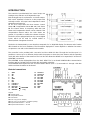
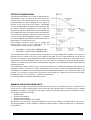
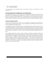
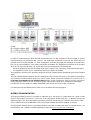
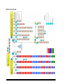
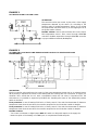
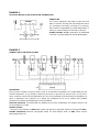
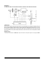
User’s Manual
W500T – W500TMB
1st Issue
01/05
1
DMP047E
TABLE OF CONTENTS
INTRODUCTION ................................................................................................................................................................................. 3
USER INTERFACE................................................................................................................................................................................ 4
FUNCTION DESCRIPTION ................................................................................................................................................................ 5
GENERAL.......................................................................................................................................................................................... 5
FOR THE 2 ANALOGUE OUTPUTS CAN BE SELECTED:.................................................................................................... 5
FOR THE 2 ON/OFF DIGITAL RELAY OUTPUTS CAN BE SELECTED:............................................................................. 6
SET-POINT COMPENSATION ...................................................................................................................................................... 8
MINIMUM AND/OR MAXIMUM LIMITS .................................................................................................................................. 8
SECOND LOOP WITH LIMIT SENSOR ..................................................................................................................................... 10
OPERATING MODE...................................................................................................................................................................... 10
MANUAL OVERRIDE KEY FOR THE OPERATING MODE .................................................................................................... 11
CLOCK ENABLE WITH TIME SCHEDULE ................................................................................................................................. 11
OUTSIDE DIGITAL ENABLE ........................................................................................................................................................ 12
FACTORY DATA LOAD ............................................................................................................................................................... 12
STORING DATA IN PERMANENT MEMORY .......................................................................................................................... 12
LOADING DATA FROM PERMANENT MEMORY .................................................................................................................. 12
REMOTE SET ................................................................................................................................................................................. 12
OUTSIDE SENSOR FROM SUPERVISION FOR COMPENSATION ...................................................................................... 13
LINK BUS COMMUNICATION .................................................................................................................................................. 13
MODBUS COMMUNICATION................................................................................................................................................... 14
ERROR SIGNALLING .................................................................................................................................................................... 15
FRONT PANEL AND DATA ACCESS MENU................................................................................................................................ 16
PARAMETER CONFIGURATION MENU................................................................................................................................... 17
Level 1
Parameter selection Parameter modification.......................................................................... 17
Parameters - Mode 1A........................................................................................................................................................ 17
Parameters - Mode 2A........................................................................................................................................................ 18
Parameters - Mode 3A / Mode 4A................................................................................................................................ 18
Parameters - Mode 1D........................................................................................................................................................ 19
Parameters - Mode 2D........................................................................................................................................................ 19
Parameters - Mode 3D........................................................................................................................................................ 19
Parameters - Mode 3D........................................................................................................................................................ 20
Parameters - Mode 4D........................................................................................................................................................ 20
PROGRAMME MENU FOR OPERATING MODES AND TIME SCHEDULES ...................................................................... 21
Settings - 0-10Volt Analogue Outputs (PA1 and PA2)................................................................................................. 22
Settings - Relay Digital Outputs (Pd1 and Pd2) – Operating Modes 1, 2 and 3 ............................................. 22
Setting - Relay digital Outputs (Pd1 and Pd2) – Operating Mode 4 ................................................................. 22
MENU DIAGRAM ......................................................................................................................................................................... 23
CONTROL PARAMETER TABLES (LEVEL 1) ............................................................................................................................ 24
TABLES OF OPERATING MODES AND TIME SCHEDULES (LEVEL 2) ............................................................................... 25
SYSTEM APPLICATIONS.................................................................................................................................................................. 27
1st Issue
01/05
2
DMP047E
INTRODUCTION
The controller is provided with four control Loops, two
Analogue Loop and two on/off Hysteresis Loops.
Each Analogue Loop is connected to a 0-10 Vdc output.
Each on/off hysteresis is linked to a relay output with
exchange contact. All Loops have independent control
parameters and set point.
All the four Loops share the three sensors: Control
Sensor SR, Compensation Sensor SC and Limit Sensor
SL. The Control Sensor is compulsory while the Limit
Sensor and Compensation Sensor can be omitted. If the
Compensation Sensors and/or the Limit Sensor are
present, it is possible to enable the relevant functions.
The device is also equipped with two dry-contact digital
inputs, which can be used for outside enable or
summer/winter changeover functions
The device is characterized by a user interface composed of a 3 ½-digit FND display, five buttons and of twelve
LEDs located on the front membrane. The information displayed on screen depends on whether the sensors
are present or not and on the related function enable.
The controller is also provided with a two-wire local bus called Link Bus. Through the local bus port it is
possible to connect up to 4 different devices with the purpose to share the three Sensors and the operating
mode with other devices of the same line. The local bus also allows the W500T to be supervised, if at least one
W500TMB is connected.
The W500TMB version distinguishes from the basic W500T for its on-board RS485-Modbus communication
interface and for the Real Time Clock with daily and weekly schedules.
The W500TMB allows supervision also for other W500T devices (max. n. 3) connected to it through a Link Bus
and the set time schedules can be shared.
Electrical connections:
1
2
3
4
5
6
7
8
9
10
11
12
GND
SR
SC
SL
GND
Di1
Di2
Link Bus +
Link Bus Bus 485 +
Bus 485 –
GND 485
W500TMB
only
13
14
15
16
17
18
19
20
22
23
24
230 Vac F
230 Vac N
Rel 1 CO
Rel 1 NA
Rel 1 NC
Rel 2 CO
Rel 2 NA
Rel 2 NC
Ao1
GND
Ao2
Legend:
SR: Control sensor
SC: Compensation sensor
SL: Limit sensor
U1: User 1 (e.g. fan or damper)
U2: User 2 (e.g. on/off valve or circulation pump)
S1: Proportional actuator 0 – 10 Volt
S2: Proportional actuator 0 – 10 Volt
1st Issue
01/05
3
DMP047E
USER INTERFACE
The device is characterized by a user interface composed
of a 3 ½-digit FND display, five keys and of twelve LEDs
located on the front membrane. The information
displayed on screen depends on whether the sensors are
present or not and on the related function enable. Using
the buttons it is possible to navigate a cascade menu,
which allows configuring individually the functions to be
assigned to the 4 independent outputs.
Description of keys
Button Up to increase values. Used both for parameter modification
and for moving inside the menus.
Button Down to decrease values. Used both for parameter modification
and for moving inside the menus.
Cancel and menu exit
Parameter programming and confirmation
Operating mode override
Description of Led
Ao1 Led associated to analogue output 1, it is on during data display.
Ao2 Led associated to analogue output 2, it is on during data display.
SR
Led associated to control sensor, it is on during data display.
SL
Led associated to limit sensor, it is on during data display.
SC
Led associated to compensation sensor, it is on during data display.
DI1 Led associated to digital input 1, it is on when the input is active (closed contact).
DI2 Led associated to digital input 2, it is on when the input is active (closed contact).
Rel1 Led associated to relay output 1, it is on when the output is active.
Rel2 Led associated to relay output 2, it is on when the output is active.
i
Led associated to anomaly signal.
Ovr Led associated to override status of the Operating Mode
Mode Led associated to Operating Mode.
On
Blinking
Off
1st Issue
Comfort
Reduced
Stop
01/05
4
DMP047E
FUNCTION DESCRIPTION
GENERAL
First of all it is necessary to define the OPERATING MODE for each one of the four Control Loops. The
Operating Mode constitutes the functioning type to be assigned to a specific output. Heating control means
that the output moves in an inversely proportional way with respect to the value measured by the Control
Sensor, vice versa is the meaning of cooling control.
FOR THE 2 ANALOGUE OUTPUTS CAN BE SELECTED:
MODE 1A: HEATING LOOP
If the output value must increase, while the Control Sensor
value goes below the Operating Set. When the set point is
achieved the output is zero. If the control Temperature goes
below the Heating Set Point value (SPC) minus the Heating
Proportional Band (BPC) the relevant analogue output goes to
100%, equivalent to10 Vdc.
MODE 2A: COOLING LOOP
If the output value must increase, while the Control Sensor
value goes above the Operating Set. When the set point is
achieved the output is zero. If the control Temperature goes
above the Cooling Set Point value (SPF) plus the Cooling
Proportional Band (BPF) the relevant analogue output goes to
100% equivalent to 10 Vdc.
MODE 3A: HEATING / COOLING LOOP FROM S/W
CHANGEOVER
If the Heating or Cooling Loop is enabled through the contact
input (D.i.2) in order to carry out a season changeover. When
the D.i.2 contact is open, the Loop passes to “Heating” control
type, under closed contact the Loop passes to “Cooling”
control type. The two “Set” (SPC, SPF) and the two
proportional bands (BPC, BPF) are independent.
MODE 4A: HEATING LOOP / COOLING IN SEQUENCE
If it is required to exploit the 1-5 6-9 V control characteristic of
CONTROLLI actuators to realize a Heating Cooling sequence
with a unique 0–10 Vdc analogue output. When the set point is
achieved the output is 5,5 Vdc. If the control Temperature
goes below the Heating Set Point value (SPC) minus Heating
Proportional Band (BPC), the relevant analogue output goes to
1 Vdc. If the control Temperature goes above the value the
Cooling Set Point value (SPF) plus Cooling Proportional Band
(BPF) the relevant analogue output goes to 9 Vdc.
In this case, if a heating-Cooling sequence is required, the two actuators must be connected n parallel to the
same output selecting the range 1 – 5 Vdc with reverse action for the actuator, which manages the heating
channel, while for the actuator managing the Cooling channel, it is necessary to select the range 6 – 9 Vdc with
direct action.
1st Issue
01/05
5
DMP047E
FOR THE 2 ON/OFF DIGITAL RELAY OUTPUTS CAN BE SELECTED:
MODE 1D: ON/OFF HEATING HYSTERESIS
If the output value must turn to ON when the value of the Control
Sensor goes below the Operating Set minus the Hysteresis band.
When the set point is achieved, the relay output is in OFF status.
MODE 2D: ON/OFF COOLING HYSTERESIS
If the output value must turn to ON when the value of the
Control Sensor goes above the Operating Set plus the Hysteresis
band. When the set point is achieved, the relay output is in OFF
status.
MODE 3D: HEATING / COOLING HYSTERESIS FROM S/W CHANGEOVER
If it is required to enable the heating or cooling hysteresis through the contact input (D.i.2) to carry out a season
changeover. When the D.i.2 contact is open, the Loop passes to “Heating” control type, under closed contact the
Loop passes to “Cooling” control type. The two “Set” (SPC, SPF) and the two proportional bands (BPC, BPF) are
independent.
MODE 4D: ON/OFF DELAY
If it is required to enable or disable a relay output with a
specified delay at stop and/or start. The delay is considered with
respect to an event, which can be:
•
•
•
ON DELAY
OFF DELAY
Operating Mode (NM and RF => ON, FA => OFF), if a stop
and/or start delay of a device following the Operating Mode
is required.
Time
The status of one of the two digital inputs (D.i.1 or D.i.2), if
it is required a stop and/or start delay of a device following the status of one or both dry contact inputs.
The status of the other Relay output, if it is required a stop and/or start delay of a device following the
status of the other digital relay output.
The ON Delay (RA) and the Off Delay (RS) can be set individually in seconds.
The events generating the changeover are according to an “OR” logic, which means that, if more than one event
condition is enabled, it is sufficient that only one is true.
The maximum allowed delay is 60 minutes.
For all Set point and Band parameter settings, see page 16.
1st Issue
01/05
6
DMP047E
CONTROL TYPE
Once the OPERATING MODE is stated, it is necessary to set the CONTROL TYPE, i.e. the control criteria used by
the OPERATING MODE. The control type can be:
• Proportional or Proportional + Integral (P or P+I)
• With fixed operation set point or compensated in function of Compensation Sensor.
• With or without minimum and/or maximum limit in function of Limit Sensor.
At this point, to improve the device understanding, it is necessary to recall some basic concepts about the used
control type used.
PROPORTIONAL CONTROL (P)
Given a SET POINT (required value), the difference between this value and the VALUE detected by the Control
Sensor is called ERROR.
A proportional control is obtained when the value of a controller output moves proportionally to the ERROR.
The PROPORTIONAL BAND determines the quantity of the action (gain) in function of ERROR. When the ERROR
is equal to the PROPORTIONAL BAND the output value is equal to 100 %.
Setting a too small PROPORTIONAL BAND can generate oscillation phenomena of the output. Setting an
excessively wide PROPORTIONAL BAND can generate a change from the SET of the controlled temperature.
PROPORTIONAL CONTROL + INTEGRAL (P+I)
If to P action is added an I action, the result is a more accurate control, which takes into account the error
variation in time. It is necessary to define an INTEGRATION TIME, which states the time, after which the
Proportional action is restored. Generally, INTEGRAL action is necessary when the PROPORTIONAL BAND allows
a variation, conferring to the INTEGRAL action the task to cancel the remaining error.
The two 0-10 Vdc analogue outputs can be P or P+I, therefore, the parameters to be set for each output will be:
• SET POINT (with fixed-point control)
• PROPORTIONAL BAND
• INTEGRATION TIME (if I action is enabled)
The 2 relay outputs can be only P, the parameters to be set will be:
• SET POINT (with fixed-point control)
• HYSTERESIS BAND
The Control Sensor used is the one connected to SR terminal, if not differently specified (“SR sharing” see
paragraph related to Link Bus). If the control sensor is not connected correctly to SR terminal or is not shared
correctly with other devices the Anomaly led i lights up.
In the OPERATING MODE 4D, the relay output behaves as a timed sequencer and it controls in function of time
events and not in function of temperature.
See page 21 to set the Operating Modes and control types.
1st Issue
01/05
7
DMP047E
SET-POINT COMPENSATION
The operation SET POINT can be fixed or determined by a
compensation curve in function of the value read by the
relevant sensor. The compensation curve is a broken line
passing between two points defined by four values. In
function of the value read by the Sensor, a SET-POINT
value in a range between a minimum and a maximum will
be defined. Negative Compensation occurs when the
Operation Set-point increases while the value measured by
the compensation sensor decreases. Positive Compensation
occurs when the Operation Set-point increases while the
value of the Compensation Sensor increases. It is possible
to set both Negative and Positive Compensations both for
heating and for cooling control Loop.
Each Operation Set-point value, both in heating and
cooling control Loop, can be associated to its own
compensation curve expressed by a value pair:
•
•
SET-POINT 1 corresponding to TEMPERATURE 1
SET-POINT 2 corresponding to TEMPERATURE 2
If the Compensation Sensor is present and the Compensation of an Operating Mode is enabled, it is necessary to
determine the four values of the curve. Such values become eight in case of Operating Mode 3A, 4A and 3D
because it is necessary to set a compensation both for the heating and for the cooling loops. In the latter case, if
compensation should be disabled for only one of the two Loops, it is necessary to set the minimum Set-point
equal to the maximum value achieving a fixed operation Set-point. It is not possible to enable compensation in
Operating Mode 4D.
The Compensation Sensor used is the one connected to SC input, if not differently specified (“SC sharing” see
paragraph related to Link Bus). To enable Compensation first connect or share the Compensation Sensor. If
compensation is enabled on any Operating Mode and the Compensation Sensor is not connected correctly to SC
terminal or is not shared correctly with other devices, the Anomaly led i lights up and the control Set-point
becomes the value set for fixed point, i.e. without Compensation.
For all compensation parameters settings see page 16.
MINIMUM AND/OR MAXIMUM LIMITS
Limit Loops are P-type only and always operate with fixed Set point. If enabled, they work in parallel to the
control Loop. For each Operating Mode (except Mode 4D) the minimum and/or maximum limits are enabled
individually. In presence of active Limits, the output values will be determined by the set parameters. For each
control Loop 4 settings are possible:
• Disabled limits
• Minimum limit enabled
• Maximum limit enabled
• Minimum and a maximum limit enabled
The behaviour of a limit Loop output will be different if the Loop is in heating or cooling Mode. For 3A, 4A and
3D operating Modes, it will be possible to enable the minimum and/or maximum limits both for heating and
cooling Mode.
1st Issue
01/05
8
DMP047E
The term “Minimum limit” indicates a function
intended to avoid that the temperature measured by
the Limit Sensor SL goes below the specified values.
The term “Maximum limit” indicates a function
intended to avoid that the temperature measured by
the Limit Sensor SL overcomes the specified values.
THEREFORE:
In a HEATING LOOP:
If the Minimum limit function is enabled, it uses the
output maximum value among the limit Loop and Control
Loop. If the Maximum limit function is enabled, it uses
the output minimum value among the limit Loop and
Control Loop.
In a COOLING LOOP:
If the Minimum limit function is enabled, it uses the
output minimum value among the limit Loop and
Control Loop. If the Maximum limit function is
enabled, it uses the output maximum value among
the limit Loop and Control Loop.
If the Minimum limit is enabled, it is necessary to
define:
• MINIMUM LIMIT SET POINT
• MINIMUM LIMIT PROPORTIONAL BAND
If the Maximum limit is enabled it is necessary to define:
• MAXIMUM LIMIT SET POINT
• MAXIMUM LIMIT PROPORTIONAL BAND
For Operating Modes 3A, 4A and 3D it is necessary to set
the Limit Set and Band values both for heating Loop and
for cooling Loop. It is not possible to enable the limit
function in Operating Mode 4D. The Limit Loop Setpoint operates at fixed point and is not modified even
under Reduced Operating Mode. The Limit Loop is
disabled under Stop Operating Mode. The Limit function
can also be used to create a Control Loop, which
performs a control of the SL sensor value independently
from sensor SR (see following paragraph).
The Limit Sensor used is the one connected to SL input, if not differently specified (“SL sharing” see paragraph
related to Link Bus). Connect or share the Limit Sensor before enabling the minimum and/or maximum Limit. If
the Limit is enabled on any Operating Mode and the Limit Sensor is not connected correctly to SL terminal or is
not shared correctly with other devices, the Anomaly Led i switches on.
For all limit parameters settings see page 16.
1st Issue
01/05
9
DMP047E
SECOND LOOP WITH LIMIT SENSOR
If the first loop does not use the Limit Function, it is possible to use the Limit Sensor as Control Sensor for the
second Loop. In this case, the second loop can be P type only with fixed Set point.
It is necessary to set the values for the Control Loop in such a way that only the limit action becomes operating.
For example, for a heating Loop that controls the SL sensor value, set an Operating Mode 1 (A or D), set the
Control Set-point at the minimum value allowed (-50°C) and enable the Minimum limit. The output controls the
Set point and the Proportional Band of Minimum limit loop.
For example if the main control Loop on the first analogue output (“PA1”) has been set freely, set the loop on
the second output (“PA2”) as follows:
SETTING PARAMETERS FOR THE SECOND HEATING LOOP
Set the Loop in MODE 1 (heating)
Enable the Minimum limit
Adjust the Control Set at the lowest value, –50°C, (in this way the output stated by the Control Loop will always
be zero)
Set the Minimum limit set
Set the Proportional Band of the Minimum limit
SETTING THE PARAMETERS FOR THE SECOND COOLING LOOP
Set the Loop in MODE 2 (Cooling)
Enable the Maximum limit
Adjust the Control Set to the highest value equal to 150 °C (in this way the output stated by the Control Loop
will always be zero)
Set the Maximum limit set
Set the Proportional Band of the Maximum limit
OPERATING MODE
The equipment is able to operate according to three different operating modes, which are:
0) Comfort – all loops are ON during control (including the Limit Loop).
1) Reduced – the Control Loops operate on a reduced Set point. The Limit Loops remain ON.
2) Stop –
all loops are 0 (including the Limit Loop).
The Operating Mode acts in parallel on all Control Loops also in Mode 4D (sequence controller), in which
Comfort and Reduced modes have the same meaning.
The passage from an Operating Mode to another can take place as follows:
•
Using the apposite Manual override key Ovr J. If it is pressed repeatedly, it is possible to access manually
to one of the three modes. This function is enabled on each Control Loop, by setting ABO = On.
For further details see page 11.
•
From Time schedule: it changes automatically into one of the three modes. This function is enabled on each
Control Loop, by setting ABO = On.
•
Through digital input D.i.1 and/or input D.i.2 (except modes 3A and 3D); if enabled (AE1 = On and/or AE2 =
On), it is possible to pass from Stop (open contact) to another mode, i.e.:
1st Issue
01/05
10
DMP047E
Changeover from digital inputs with dry contact operates on all Loops whose function is enabled (AE1 or AE2
with value On). Such operation has a priority with respect to other changeovers (from clock or Manual override
button).
The Stop mode in Mode 4A produces a 5,5 Vdc output.
The enabled Operating Mode is signalled by a proper Led Mode on the front panel, as follows:
Led Mode Status
Operating Mode enabled
ON
Comfort
Blinking
Reduced
Off
Stop
Through the Link Bus, it will be possible to share the override mode although a local override on a single
equipment has always priority with respect to the shared mode.
The Operating mode is determined by default by the Time schedule, if the clock is present, otherwise the default
Operating Mode is Comfort. The manual override through key loses its action, if the equipment is switched off
and then on again. For further details, see the three following paragraphs.
MANUAL OVERRIDE KEY FOR THE OPERATING MODE
It is possible to carry out a manual override of the Operating Mode by pushing the proper key Ovr J inside the
Operating Mode Programme Menu accessed by pushing the Set key for 5 seconds.
The manual override cancels the mode determined by the clock and it is signalled by the Led Ovr on the front
panel. The number of clicks on such key, states cyclically the setting, passing from Comfort, to Reduced and Stop
modes, then returning to Automatic mode.
CLOCK ENABLE WITH TIME SCHEDULE
If the W500 is RTC-provided or it is connected via Link Bus to a device with clock, it is possible to define the
Operating Mode according to a weekly schedule and a daily schedule. The clock enable of each Control Loop is
obtained by setting the parameter ABO = On. If the device with clock is connected to other equipments without
clock through the Link Bus, the mode can be shared and all the equipments will follow simultaneously the same
time schedule.
Weekly schedule:
For each day of the week it is possible to define a fixed mode (0 = Comfort, 1 = Reduced, 2 = Stop) or to assign
a daily schedule (expressed by value 3).
Daily schedule:
It is possible to carry out up to 4 time changeovers defining, for each one, hour, minute and mode.
The changeovers, which are not used, must be filled in with the same values of the last valid changeover.
For the setting of both weekly and daily time schedules, see page 21.
1st Issue
01/05
11
DMP047E
OUTSIDE DIGITAL ENABLE
Two digital inputs are available: they can be used independently by the 4 Control Loops. If on a Control Loop the
Outside enable (AE1 or AE2 a value On) has been started, it is possible to start and/or stop the Loop from an
outside contact. If both the outside enables are ON, the Control Loop stops only if both contacts are open.
For clock models, the contact enables only the loop outside the operating time (if the equipment is “On” from
the clock, it cannot be set to off by digital input)
If the Loop is configured to operate in Mode 3A or 3D (Heating / Cooling by S/W Changeover) the digital input 2
is used only for this purpose. The enabling from contact acts a priority with respect to the other changeovers
(from clock or manual override with Ovr key).
Mode Contact D.i.1
AE1 = On
Open
COMFORT
STOP
RIDOTTO
STOP
STOP
STOP
(*) This function is not ON in 3A and 3D modes.
Operating
ON
Closed
COMFORT
REDUCED
COMFORT
Contact D.i.2 (*)
AE2 = On
Open
STOP
STOP
STOP
Closed
COMFORT
REDUCED
COMFORT
FACTORY DATA LOAD
Through this function it is possible, if required, to reset all the factory settings of parameters.
This function is useful for example when the user has set different values and requires restoring the initial
conditions in a short time.
STORING DATA IN PERMANENT MEMORY
Once the parameters for a plant are set, it is possible to store such settings in order to restore them when
required.
LOADING DATA FROM PERMANENT MEMORY
This function allows restoring all the configurations and the parameters, which were previously saved by
MEMORY DATA STORAGE function.
REMOTE SET
When a control with Fixed-point set is required, the Compensation Sensor is not used.
In this case, it is possible to connect a suitable potentiometer (instead of the Compensation Sensor local input)
to carry out a remote setting of the Operation Set-point.
PARAMETER SETTING
Enable Compensation and define the four points of the line:
Keep into the account that TEMPERATURE 1 corresponds to the value read at a potentiometer end and
TEMPERATURE 2 to the value read at the other end.
1st Issue
01/05
12
DMP047E
•
•
SET 1 corresponding to TEMP 1
SET 2 corresponding to TEMP 2
The value displayed by the Compensation Sensor is purely indicative and does not correspond to the actual
temperature in °C.
OUTSIDE SENSOR FROM SUPERVISION FOR COMPENSATION
If the function is ON (USE = On), it is possible to carry out compensation through a value sent from the
Communication Bus with ModBus protocol (supervision). In practice it is a virtual sensor, which can be used
instead of a real sensor connected to SC terminal. If, for example, there is only one outside sensor in the whole
plant, this function allows using its value on all controllers connected to the supervision system. Similarly it
would be possible, from supervision, to set a single Operation Set-point for the different equipments connected.
LINK BUS COMMUNICATION
The Link Bus serial communication port allows to 2, 3 or 4 equipments to interoperate for data exchange. The
Link Bus connection allows sharing the three sensors and Operating Mode and supervising the devices, which do
not have the RS485 serial communication port.
The equipments connected via Link Bus must have a univocal address (IDL) that can be set by the menus from 1
to 4. The equipment with IDL = 1 (Master) communicates its Operating Mode to the other controllers connected
to the Link Bus. If the Master is RTC-provided (RTC is not necessary for the others), the 4 controllers can operate
according to the same time schedule. The equipments without the RS485 (W500T) serial communication port
can be supervised if connected via Link Bus to at least one equipment with RS485 (W500TMB), setting it as
Master.
Each IDL address corresponds to a Link Bus “channel” on which the controller communicates the values of its
own temperature sensors connected to the terminals. Each device communicates its values on the Link Bus
channel determined by the assigned IDL address number. If it is required a sensor connected to the terminals of
another controller, it is necessary to operate on parameters menu of Sensor Selection (SEL) and to select the
channel for reading. For example, a controller with IDL address = 2, which uses the Compensation Sensor
connected to SC terminals of the equipment having IDL address = 3, the value SSC in the sensor selection
parameter menu (SEL) must be = 3. If the sensor to be used is connected to the controller terminals, the setting
will be SSC = 2. For each one of three sensors it is necessary to specify its location. If the sensor is local, it is
necessary to state the proper IDL address.
1st Issue
01/05
13
DMP047E
In order to communicate the values through the Link Bus port, it is also necessary to set the number of devices
interconnected by the parameter NDL (4 max.). The equipments connected to the Link Bus, which must not
transmit data, can be set with NDL = 1. Such configuration is allowed (to speed data exchange on the Link Bus),
but it is not recommended in case of data monitoring via ModBus. The equipments connected to the Link Bus
which do not communicate data, can receive data from other equipments. It is essential that:
- the other equipments have the same NDL value as the number of the controllers, communicating the values
- the equipments, which do not communicate data, have a higher IDL address.
The equipments, which are RTC-provided, always use the their Operating Mode changeover ignoring the Link Bus
signal.
The max advisable distance between the two equipments at the Link Bus ends is 10 m. This distance should allow
any connection inside the electrical board. In case of power devices (Contactors, Inverters, UPS, reactors, etc.) it
is strongly recommended to use shielded cables with the screen connected to earth at one point only and to
keep at a suitable distance (30 cm. at least) the power cables and the signal wires, otherwise use metal pipes.
It is advisable to use a 24AWG or 26AWG twisted-pair cable and do not carry out star connections.
For setting the Link Bus address and to select one of the sensors shared, see page 16.
MODBUS COMMUNICATION
Through the ModBus protocol it is possible to supervise up to 255 groups of 4 equipments, for a total of 1020
devices. The ModBus connection is carried out on the equipment defined with IDL = 1 (Master) through the
RS485 serial port. The values managed by supervision and those managed by the controller menu are the same.
For the address values of ModBus data, refer to the proper DataBase documents supplied on request.
The wiring path between the two most distant devices connected to RS485 serial must not exceed 1000 m.: we
recommend to use a 24AWG or 26AWG twisted-pair cable and not to carry out star connections.
1st Issue
01/05
14
DMP047E
The first and the last device must be terminated by a 120-Ohm ¼-Watt resistance.
If devices from different manufacturers are present on the same communication Bus, it is necessary to respect
the limits imposed and to be careful not to use the same ModBus addresses of other devices. We recommend
using a shielded cable for RS485 Bus if on the plant or inside the switchboard are present power devices, always
keeping the suitable distances and precautions regarding signal wiring and power cables.
For ModBus address set up and outside compensation from supervision, see page 21.
ERROR SIGNALLING
The controller is able to signal two anomaly conditions, one depending from communication and the other from
Sensors.
If a Communication ERROR is present, the Anomaly Led i blinks. It is possible to have a communication fault
when, for example, two equipments connected via Link Bus use the same IDL address or in case of high noise on
communication, which provokes faulty data transmission. Inside switchboards, in presence of power devices
(contactors, Inverters, UPS, reactors, etc.), we recommend to use shielded cables (both for sensors and Bus)
to reduce anomaly probability.
If a sensor anomaly occurs, the Anomaly Led i lights up. If both anomaly conditions occur, the Led blinks. Once
the Communication anomaly is cancelled, the Led remains on indicating the Sensor ERROR.
For a correct operation the anomaly Led must be switched off.
The conditions, which most frequently produce anomalies, are:
• Sensor is no more present with enabled function
• Sensor outside the controller (shared with Link Bus) is not present
• More devices have the same IDL address
1st Issue
01/05
15
DMP047E
FRONT PANEL AND DATA ACCESS MENU
Using Front Panel, it is possible to access the Parameters managed
by the device. The data access Menu is subdivided into three
different levels:
Level 0 – Main data display
Level 1 – Access to parameter configuration menu
Level 2 – Access to the Operating modes programming menu
The Level 0 is the one displayed by default. If no keys are pushed
for some seconds this level is automatically re-entered from the higher levels.
At this Menu level it is possible to visualize on the FND display the temperature values of the connected sensors
(also via Link Bus) and the analogue outputs Ao1 and Ao2 values expressed as a percentage. Data display is
achieved by pushing the buttons Up
or Down
; while Led signalling the displayed analogue input or
output lights up. If an input is not present, it is not displayed. The digital input led D.i.1 and D.i.2 are on with
closed contact, the Rel1 and Rel2 relay output led are on if they are energized. Such led are always visible at any
menu level. The Mode, Ovr and anomaly i LEDs have already been described in the respective chapters.
To access Level 1, push the Set key. At this level it is possible to change the control Parameters of the two
analogue outputs [PA1] and [PA2], of the two Relay Digital outputs [Pd1] and [Pd2] and, for W500TMB
controllers only, also the clock [ rtc ]. It is always necessary to set the clock at the first start-up or if the
equipment has been powered off for over 30 hours. In order to set date and time, scroll the menu at the level 1
until the corresponding label [ rtc ] is reached. The label [ d00 ] (days, d00 = Monday) appears by pushing the
Set key. Push the buttons Up or Down to set. If the key are not pushed for some seconds or by pressing Set,
the label [ h00 ] (hours) and [ ’00] (minutes) appears: push the buttons Up and Down to set respectively hour
and minutes. To confirm and save, push Set. If the keypad is not pushed or by pressing the Esc key once, the
start value appears.
[PA1] label corresponds to the Parameters of Analogue output 1 at Ao1 terminal
[PA2] label corresponds to the Parameters of Analogue output 2 at Ao2 terminal
[Pd1] label corresponds to the Parameters of Digital output 1 of Rel1 relay
[Pd2] label corresponds to the Parameters of Digital output 2 of Rel2 relay
To modify a parameter, it is necessary to push Set after selecting the corresponding Label; the parameter value
blinks and can be changed by pushing the keys Up to increase or Down to decrease. Push Set or Esc to exit. For
the complete control parameter navigation see the Parameter Configuration Menu scheme on page 17.
By pushing the Set key for at least 5 seconds, Level 2 appears. At this menu level, it is possible to set:
the Operating-Set decrease to Reduced mode
the operating modes of the two analogue outputs [PA1] and [PA2] and of the two relay digital outputs
[Pd1] and [Pd2]
the address parameters for communication, for sensor selection, for data load, save, restore and, for
W500TMB devices only, also the time schedules for the automatic changeover of the weekly and daily
Operating Mode.
For data navigation see Programme menu for operating mode and time schedules on page 21 Note: the time
schedules are present only on W500TMB.
1st Issue
01/05
16
DMP047E
PARAMETER CONFIGURATION MENU
Level 1
Set
Parameter selection
PA1
Set
PA2
Set
Pd1
Set
Pd2
Parameter modification
Set
Set
parameters
Set
parameter
s
parameters
Set
Set
rtC
Set
d00
Day set
h00
Hour Set
‘00
Minute Set
Parameters - Mode 1A
Push the Set Key to change of the relevant parameter. The parameter value blinks showing the edit status:
push the Up and Down keys to change values. Once the desired values are modified, push the Set or Esc
keys to exit.
S0C
Heating operating Set-point (read-only if the compensation is ON)
Visible only with Compensation ON (coP parameter = On )
Sc1
Minimum Set-point of Heating compensation
tc1
Minimum Temperature of Heating Compensation
Sc2
Max Set point of Heating Compensation
tc2
Max Compensation of heating Compensation
bPC
Heating Proportional Band
Visible only with Integral ON (int parameter = On )
tiC
Heating Integral time
Visible only with Minimum limit ON ( LLL parameter = On )
SLC
Minimum Limit Set point for Heating
bLC
Minimum Proportional band for Heating
Visible only with Max limit ON (LLH parameter = On )
SHC
Maximum Limit Set point for Heating
bHC
Maximum Proportional band for Heating
1st Issue
01/05
17
DMP047E
Parameters - Mode 2A
Push Set key to select the parameter to be modified. The parameter value blinks showing the edit status:
push the Up and Down keys to change values. Once the desired values are modified, push the Set or Esc
keys to exit.
SoF
Cooling operating Set-point (read-only if Compensation is ON)
Visible only with Compensation ON (coP parameter = On )
Sc3
Minimum Compensation Set point for Cooling
tc3
Minimum Compensation temperature for Cooling
Sc4
Maximum Compensation Set point for Cooling
tc4
Maximum Compensation temperature for Cooling
bPF
Cooling Proportional Band
tiF
Visible only with Integral ON (int parameter = On
Cooling Integral time
Visible only with Minimum limit ON ( LLL parameter = On )
SLF
Cooling Minimum Set-point Limit
bLF
Heating minimum proportional Band limit
Visible only with Maximum limit On (LLH parameter = On )
SHF
Maximum Limit Set point for Heating
bHF
Maximum Proportional Band Limit for Heating
Parameters - Mode 3A / Mode 4A
The parameter menu of the Analogue Operating Modes 3A/4A is the sum of 1A/2A Modes parameter
menus. This Menu contains all parameters, since this modes are intended manage both heating and cooling
control loops.
Push Set key to select the parameter to be modified. The parameter value blinks showing the edit status:
push the Up and Down keys to change values. Once the desired values are modified, push the Set or Esc
keys to exit.
The Compensation/Integral/Limit parameters are visible if the relevant functions in the Operating Mode
Programme menu (2° Level) are enabled. Push Set key for 5 seconds to enter the menu.
1st Issue
01/05
18
DMP047E
Parameters - Mode 1D
Push Set key to select the parameter to be modified. The parameter value blinks showing the edit status
which is carried out by pushing the Up key to increase the value and Down to decrease it. Once the desired
values are modified, push the Set or Esc keys to exit.
SoC
Heating operating Set point (read-only if the Compensation is ON)
Visible only with Compensation ON (coP parameter = On )
Sc1
Minimum Set-point of Heating compensation
tc1
Minimum Temperature of Heating compensation
Sc2
Maximum Set-point of Heating compensation
tc2
Maximum Temperature of Heating compensation
bPC
Heating Proportional Band
Visible only with Minimum limit ON ( Parameter LLL = On )
SLC
Minimum Limit Set point for Heating
bLC
Minimum Proportional Band Limit for Heating
Visible only with max. limit ON (LLH parameter = On )
SHC
Maximum Limit Set point for Heating
bHC
Maximum Proportional Band Limit for Heating
Parameters - Mode 2D
SoF
Cooling operating Set-point (read-only if Compensation is ON)
Visible only with Compensation ON (coP parameter = On )
Sc3
Cooling compensation min. Set point
tc3
Cooling compensation min. Temperature
Sc4
Cooling compensation max. Set-point
tc4
Cooling compensation max. Temperature
bPF
Cooling proportional band
Visible only with Min. limit ON (LLL parameter = On )
SLF
Minimum Limit Set point for Cooling
bLF
Cooling
Visible only with max. limit ON (LLH parameter= On )
SHF
Maximum Limit Set point for Heating
bHF
Maximum Proportional Band Limit for Heating
1st Issue
01/05
19
DMP047E
Parameters - Mode 3D
The Parameter menu of On/OFF Hysteresis Digital operating Mode 3D is the sum of 1D/2D Modes
parameter menus. This Menu contains all parameters, since this mode is intended to manage both heating
and cooling control loops.
Push Set key to select the parameter to be modified. The parameter value blinks showing the edit status:
push the Up and Down keys to change values. Once the desired values are modified, push the Set or Esc
keys to exit.
The Compensation and Limit parameters are visible if the relevant functions in the Operating Mode
Programme menu (2° Level) are enabled. Push Set key for 5 seconds to enter such menu
Parameters - Mode 4D
Push Set key to select the parameter to be modified. The parameter value blinks showing the edit status:
push the Up and Down keys to change values. Once the desired values are modified, push the Set or Esc
keys to exit.
trS
Switch-off Delay time in seconds
trA
Switch-on Delay time in seconds
1st Issue
01/05
20
DMP047E
PROGRAMME MENU FOR OPERATING MODES AND TIME SCHEDULES
Set
Pro
Level 2
Push Set for 5 seconds
Set
Pr7
Set daily schedule at fixed mode or time changeover
Set
d0
Set
d6
Set time schedules and operating mode
Set
Prd
co1
Set
co4
Set Reduced mode for Heating and cooling
rid
Set
rid C
Set
rid F
PA1
Set
Setting
Set
PA2
Set
Setting
Set
Pd1
Set
Setting
Set
Pd2
Set
Setting
Set
Set Sensor selection channel
SSr
SSc
SEL
Set
SSL
Set
USE
buS
Set
ndL
idL
ibS
Set Link Bus and ModBus addresses
Set
dEF
Set
Push Set for 5 seconds until the device is reset (the display blinks)
SdE
Set
Push Set for 5 seconds until the label YES appears
LdE
1st Issue
Set
21
Push Set for01/05
5 seconds until the equipment
is reset (the display blinks) DMP047E
Settings - 0-10Volt Analogue Outputs (PA1 and PA2)
oP
Operating mode selection
Abo
Enable from Time schedule (if present) or permanent enable
int
P+I Control enable
coP
Compensated or remote Set point enable
LLL
Min. limit enable
LLH
Max. limit enable
AE1
Loop enable from D.i.1 Switch
Visible only with 1, 2 and 4 operating modes
AE2
Loop enable from D.i.2 Switch
Settings - Relay Digital Outputs (Pd1 and Pd2) – Operating Modes 1, 2 and 3
oP
Operating mode selection
Abo
Enable from Time schedule (if present) or permanent enable
coP
Compensated or remote Set point enable
LLL
Min. limit enable
LLH
Max. limit enable
AE1
Loop enable from D.i.1 Switch
Visible only with 1 and 2 operating modes
AE2
Loop enable from D.i.2 Switch
Setting - Relay digital Outputs (Pd1 and Pd2) – Operating Mode 4
oP
Operating mode selection
Abo
Enable from Time schedule (if present) or permanent enable
SEo
Relay enable by other relay contact
rS
Enable switch off delay of Relay
rA
Enable switch on delay of Relay
AE1
Relay enable from D.i.1 outside switch
AE2
Relay enable from D.i.2 outside switch
1st Issue
01/05
22
DMP047E
MENU DIAGRAM
1st Issue
01/05
23
DMP047E
CONTROL PARAMETER TABLES (LEVEL 1)
Parameter table: Level 1 (Loop adjustment Parameters)
Analogue
Controller
PA1 & PA2
SoC
SoF
Default Range
Description
Availability
--
Heat operating Set
Always (Visualisation only, cannot be set)
--
Cool operating Set
Always (Visualisation only, cannot be set)
StC
21.0 -50 to 150 Heat Loop Set
Sc1
20.0 -50 to 150 Heating compensation min. Set
tc1
5.0
Sc2
35.0 -50 to 150 Heating compensation max. Set
tc2
10.0 -50 to 150 Heating compensation max. temperature
tiC
480
bPc
4.0
SLc
18.0 -50 to 150 Heating min. limit Loop Set
With LLL enabled, 1, 3 and 4 operating mode
SHc
24.0 -50 to 150 Heating max. limit Loop Set
With LLH enabled, 1, 3 and 4 operating mode
SLF
18.0 -50 to 150 Cooling min. limit Loop Set
With LLL enabled, 2, 3 and 4 operating mode
SHF
24.0 -50 to 150 Cooling max. limit Loop Set
With LLH enabled, 2, 3 and 4 operating mode
bLc
4.0
0 to 25 Heating min. limit. Proportional Band
With LLL enabled, 1, 3 and 4 operating mode
bHc
4.0
0 to 25 Heating max. limit Proportional Band
With LLH enabled, 1, 3 and 4 operating mode
bLF
4.0
0 to 25 Cooling min. limit Proportional Band
With LLL enabled, 2, 3 and 4 operating mode
bHF
4.0
0 to 25 Cooling max. limit Proportional Band
StF
23.0 -50 to 150 Cooling Loop Set
Sc3
10.0 -50 to 150 Cooling compensation min. Set
With SR and SC,Comp. enabled, 2, 3 and 4 operating mode
tc3
10.0 -50 to 150 Cooling compensation min. Temperature
With SR and SC,Comp. enabled, 2, 3 and 4 operating mode
Sc4
30.0 -50 to 150 Cooling compensation max. Set
With SR and SC, Comp.enabled, 2, 3 and 4 operating mode
tc4
15.0
-50 a 150 Cooling compensation max. Temperature
With SR and SC, Comp. enabled, 2, 3 and 4 operating mode
tiF
480
30 a 1200 Cooling integral time (sec)
With integral action enabled
bPF
4.0
Reg. On/Off
Pd1 & Pd2
-50 to 150 Heating compensation min. temperature
30 to 1200 Heating integral time (sec)
0 to 25 Heating Loop Proportional Band
With SR, 1, 3 and 4 operating mode
With LLH enabled, 2, 3 and 4 operating mode
With SR, without Compens., 2, 3 and 4 operating mode
0 to 25 Cooling Loop Proportional Band
Default Range
With SR, without Compens., 1, 3 and 4 operating mode
With SR and SC, Comp. enabled, 1, 3 and 4 operating
mode
With SR and SC, Comp. enabled, 1, 3 and 4 operating
mode
With SR and SC, Comp. enabled, 1, 3 and 4 operating
mode
With SR and SC, Comp. enabled, 1, 3 and 4 operating
mode
With integral action enabled
With SR, 2, 3 and 4 operating mode
Description
Availability
SoC
--
Heating operating Set
Always (Visualisation only, cannot be set)
SoF
--
Cooling operating Set
Always (Visualisation only, cannot be set)
StC
21.0 -50 to 150 Heating ON/OFF Set
With SR, without Compens., 1 and 3 operating mode
Sc1
20.0 -50 to 150 Heating compensation min. Set
With SR and SC, Comp. enabled, 1 and 3 operating mode
tc1
5.0
Sc2
35.0 -50 to 150 Heating compensation max. Set
tc2
10.0 -50 to 150 Heating compensation max. Temperature
With SR and SC, Comp. enabled, 1 and 3 operating mode
bPc
4.0
With SR, 1 and 3 operating mode
SLc
18.0 -50 to 150 Heating min. ON/OFF limit Set
With LLL enabled, 1 and 3 operating mode
SHc
24.0 -50 to 150 Heating max. ON/OFF limit Set
With LLH enabled, 1 and 3 operating mode
SLF
18.0 -50 to 150 Cooling min. ON/OFF limit Set
With LLL enabled, 2 and 3 operating mode
SHF
24.0 -50 to 150 Cooling max. ON/OFF limit Set
With LLH enabled, 2 and 3 operating mode
bLc
4.0
0 to 25
Heating min. ON/OFF limit Hysteresis
With LLL enabled, 1 and 3 operating mode
bHc
4.0
0 to 25
Heating max. ON/OFF limit Hysteresis
With LLH enabled, 1 and 3 operating mode
bLF
4.0
0 to 25
Cooling min. ON/OFF limit Hysteresis
With LLL enabled, 1 and 3 operating mode
bHF
4.0
0 to 25
Cooling max. ON/OFF limit Hysteresis
With LLH enabled, 1 and 3 operating mode
StF
24.0 -50 to 150 Cooling ON/OFF Set
Sc3
8.0
-50 to 150 Cooling compensation min. Set
With SR and SC, Comp. enabled, 2 and 3 operating mode
tc3
0.0
-50 to 150 Cooling compensation min. temperature
With SR and SC, Comp. enabled, 2 and 3 operating mode
Sc4
15.0 -50 to 150 Cooling compensation max. Set
tc4
40.0 -50 to 150 Cooling compensation max. temperature
With SR and SC, Comp. enabled, 2 and 3 operating mode
bPF
4.0
With SR, 2 and 3 operating mode
trS1st
trA
Issue
-50 to 150 Heating compensation min. Temperature
0 to 25
0 to 25
Heating ON/OFF Hysteresis
With SR, without Compens., 2 and 3 operating mode
Cooling ON/OFF Hysteresis
0
0 to 1999 Switch
off delay time (sec)
01/05
0
0 to 1999 Switch on delay time (sec)
With SR and SC, Comp. enabled, 1 and 3 operating mode
With SR and SC, Comp. enabled, 1 and 3 operating mode
24
With SR and SC, Comp. enabled, 2 and 3 operating mode
Operating mode 4
Operating mode 4
DMP047E
TABLES OF OPERATING MODES AND TIME SCHEDULES (LEVEL 2)
Parameter table: Level 2 (Time schedules, Operating modes, Special functions)
Time schedules (Pro)
Weekly
Default
schedule (Pr7)
d0 (MON)
3
d1 (TUE)
3
d2 (WED)
3
d3 (THU)
3
d4 (FRI)
3
d5 (SAT)
1
d6 (SUN)
2
Daily schedule
Default
Description
Availability
Fixed mode or daily schedule (NM,RF,FA,PG)
Fixed mode or daily schedule(NM,RF,FA,PG)
Fixed mode or daily schedule (NM,RF,FA,PG)
Fixed mode or daily schedule (NM,RF,FA,PG)
Fixed mode or daily schedule (NM,RF,FA,PG)
Fixed mode or daily schedule (NM,RF,FA,PG)
Fixed mode or daily schedule (NM,RF,FA,PG)
If clock is present (W500TMB model)
If clock is present (W500TMB model)
If clock is present (W500TMB model)
If clock is present (W500TMB model)
If clock is present (W500TMB model)
If clock is present (W500TMB model)
If clock is present (W500TMB model)
Description
Availability
Change-over time 1
Change-over minutes 1
Change-over mode 1 (NM, RF, FA)
Change-over time 2 (0-23)
Change-over minutes 2 (0-59)
Change-over mode 2 (NM, RF, FA)
Change-over time 3 (0-23)
Change-over minutes 3 (0-59)
Change-over mode 3 (NM, RF, FA)
Change-over time 4 (0-23)
Change-over minutes 4 (0-59)
Change-over mode 4 (NM, RF, FA)
If clock is present (W500TMB model)
If clock is present (W500TMB model)
If clock is present (W500TMB model)
If clock is present (W500TMB model)
If clock is present (W500TMB model)
If clock is present (W500TMB model)
If clock is present (W500TMB model)
If clock is present (W500TMB model)
If clock is present (W500TMB model)
If clock is present (W500TMB model)
If clock is present (W500TMB model)
If clock is present (W500TMB model)
Description
Availability
Heating Set decrease
Cooling Set decrease
Always
Always
Analogue contr.
Default Range
PA1 & PA2
Description
Availability
Op
1
Operating mode (1, 2, 3, 4)
Abo
Int
coP
LLL
LLH
AE1
OFF
OFF
OFF
OFF
OFF
OFF
Automatic/Manual enable (Clock)
Integral action enable
Compensated set enable
Min. limit loop (Low) enable
Max. limit loop (High) enable
Loop stop on DI1 (External enable 1)
AE2
OFF
Loop stop on DI2 (External enable 2)
(Prd)
co 1: h
:'
:r
co 2: h
:'
:r
co 3: h
:'
:r
co 4: h
:'
:r
Reduced Set
(rid)
RiC
RiF
7
30
0
12
30
1
13
30
0
19
0
2
Range
0 to 3
0 to 3
0 to 3
0 to 3
0 to 3
0 to 3
0 to 3
Range
0 to 23
0 to 59
0 to 2
0 to 23
0 to 59
0 to 2
0 to 23
0 to 59
0 to 2
0 to 23
0 to 59
0 to 2
Default Range
3
5
0 to 20
0 to 20
Operating modes
On/Off contr.
Pd1 & Pd2
1 to 4
Default Range
With SC sensor
With SL sensor
With SL sensor
Always
1, 2 and 4 operating mode. 3 Mode: S/W (off)
Changeover
Description
Availability
Operating mode (1, 2, 3, 4)
Automatic/Manual enable (Clock)
Compensated Set enable
Min. (Low) ON/OFF limit enable
Max. (High) ON/OFF limit enable
Loop stop on DI1 (External enable 1)
Always
Always
With SC, 1, 2 and 3 operating mode
With SL, 1, 2 and 3 operating mode
With SL, 1, 2 and 3 operating mode
Always
1, 2 and 4 operating mode. In Mode3: S(on)/W (off)
Changeover
Operating mode 4
Operating mode 4
Operating mode 4
Op
Abo
coP
LLL
LLH
AE1
1
OFF
OFF
OFF
OFF
OFF
AE2
OFF
Loop stop on DI1 (External enable 2)
SEo
RS
RA
OFF
OFF
OFF
Other ON/OFF control enable
Switch off delay enable
Switch on delay enable
1st Issue
1 to 4
Always
Note: for details about the
Operating modes see also the data sheet
Always
Always
01/05
25
DMP047E
Special Functions
Sensor
Default
selection (SEL)
SSr
1
SSc
1
SSL
1
SSE
1
USE
OFF
Communication
Default
(buS)
ndL
1
idL
1
ibS
1
1st Issue
Range
1 to 4
1 to 4
1 to 255
Description
Availability
Control sensor selection
Compensation sensor selection
Limit sensor selection
Selection for external sensor to device
Compensation sensor enable by ModBus
Always
Always
Always
Always
Always
Description
Availability
Number of devices on LinkBus (1 - 4)
LinkBus position (1 - ndL)
ModBus Supervisor bus address
Always
Always
Always
01/05
26
DMP047E
SYSTEM APPLICATIONS
EXAMPLE 1:
OUTSIDE AIR PLANT WITH TIME CONTROL OF ROOM TEMPERATURE IN WINTER
OPERATION
The controller carries out time control, with P+I action, on room temperature (sensor 2A) or on air exhaust
(sensor 2B) by driving the valve (4) on the heating coil. In case the supply temperature (3) goes below the
set limit value, the controller intervenes with P action, changing the valve position to avoid that excessively
cold air is introduced into the environment. It is possible to supervise by ModBus also visualizing the status
of the differential pressure switch on the filter.
Frost protection: in case of heated fluid lack or of faulty control, if the anti-frost thermostat (5) detects a
temperature lower than the set value, the controller stops the fan and closes the outside air damper.
Obstructed filter: the pressure switch (7) signals the presence of obstructed filter if the differential
pressure before and after the filter, increases over the set value.
Possible variants:
- fan control on exhaust on digital output Rel2 with switch-on delay with respect to the supply fan
- remote set point of the heating coil on SC input, or compensated outside set point.
1st Issue
01/05
27
DMP047E
EXAMPLE 2:
HOT WATER PLANT FOR FAN COILS
OPERATION
The controller carries out control, by P+I action, of the supply
temperature detected by the sensor (3), according to the
function value of outside temperature, sensor (1), by driving
the proportional motorized valve (2) on the tapping circuit of
the power station collector.
Possible variants: control with minimum limit on the return
fluid temperature sensor. Time control through W500TMB
controller. ModBus supervision through W500TMB controller
or proper additional module (BusAdapter).
EXAMPLE 3:
OUTSIDE AIR PLANT WITH TIME TEMPERATURE CONTROL OF HEATING/COOLING
ENVIRONMENT
OPERATION
The P+I controller action performs time control of the room temperature (sensor 2A) or air exhaust (sensor
2B) by driving in sequence the valves on the heating (4B) and cooling (4A) coils. The sensor on supply (3),
minimum limit, avoids that the air with a temperature below the set value is introduced into the
environment. It is possible to supervise by ModBus also visualizing the status of the differential pressure
switch on the filter.
Frost protection: in case of heating fluid lack or of faulty control, if the anti-frost thermostat (5) detects a
temperature lower than the set value, the controller stops the fan and closes the outside air damper.
Frost protection: in case of heating fluid lack or of faulty control, if the anti-frost thermostat (5) detects a
temperature lower than the set value, the controller stops the fan and closes the outside air damper.
Possible Variants:
- - fan control on exhaust on digital output Rel2 with switch-on delay with respect to the supply fan
- remote set point of the heating coil on SC input, or compensated outside set point.
1st Issue
01/05
28
DMP047E
EXAMPLE 4:
HOT/COLD WATER PLANT IN WITH S/W CHANGEOVER
OPERATION
The circuit is supplied by hot water in winter and cold
water in summer. Through the S/W changeover switch
(5), according to the season, the valve (2) is driven by
the controller compensated by outside temperature in
winter (1), by the fixed-point controller in summer.
Possible variants: ModBus supervision by W500TMB
controller or proper additional module (BusAdapter).
EXAMPLE 5:
PRIMARY AIR PLANT WITH RE-HEAT
OPERATION
The P+I action controller carries out time control of the saturation temperature (2) compensated with the
outside temperature (7), by driving in sequence the valves on pre-heat (3) and pre-cool (4) coils. The P
action controller controls reheat temperature (6). The room humidistat (9) drives directly the humidifier; its
action is signalled to the controller. As a variant, the humidistat can be on air exhaust duct. ModBus
supervision is possible also displaying the on/off humidifier.
Anti-frost protection: The thermostat (10) disables the fan and, consequently, the damper actuator (11)
on the outside air is closed.
Possible variants:
- fan control on air exhaust on Rel2 digital output with switch-on delay with respect to the supply fan Rel1.
Possible alternatives: Electrical mono-phase reheat coil with ON/OFF action on Rel2, which controls
supply temperature (6).
1st Issue
01/05
29
DMP047E
EXAMPLE 6:
OUTSIDE AIR TIME PLANT AND WATER SERVICE CONTROL WITH RAPID EXCHANGER
OPERATION
The P+I action controller carries out time control of room temperature (6), driving the heating/cooling coil
with S/W mode through changeover switch (4) and remote set through potentiometer selector (5). The P
action controller maintains at the set value the water temperature detected by the sensor (8), to the user,
by driving the proportional valve (9), which mixes water from the waterworks and return with the water
from the exchanger. The 2-position safety thermostat (7) closes the valve, if the User temperature exceeds
the set value.
Possible variants:
- fan control on air exhaust on Rel2 digital output with switch-on delay with respect to the supply fan Rel1.
1st Issue
01/05
30
DMP047E