1
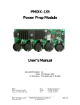
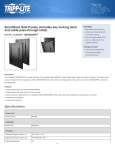
PMDX-103
Parallel Port Isolator Board
User’s Manual
Document Revision: 1.2
Date: 20 February 2007
PCB Revision: PCB-447B
PMDX
9704-D Gunston Cove Rd
Lorton, VA 22079-2366 USA
PMDX-103_Manual_12.doc
20 February 2007
Web:
Phone:
FAX:
http://www.pmdx.com
+1 (703) 372-2975
+1 (703) 372-2977
©2005-2007, Practical Micro Design, Inc.
All Rights Reserved
Page 1 of 10
PMDX-103 User’s Manual
PCB Revision: PCB-447B
Document Revision: 1.2
Table of Contents
1.0
Overview.................................................................................................................................... 3
1.1
Ordering Information (part numbers) ........................................................................................................... 3
1.2
Important Safety Information ........................................................................................................................... 3
1.3
Warranty Summary............................................................................................................................................. 3
1.4
Features.................................................................................................................................................................. 4
1.5
Updates to this Manual ...................................................................................................................................... 4
2.0
Connectors ................................................................................................................................ 4
2.1
PC Parallel Port (J1 and J2) ............................................................................................................................... 4
2.2
Alternate Power Connector (J4)..................................................................................................................... 6
2.3
Equipment Connector (J5 and J3) ................................................................................................................... 6
2.4
Power Connector (J6)........................................................................................................................................ 7
3.0
Power LED (D4) ....................................................................................................................... 7
4.0
Grounding and Isolation Issues............................................................................................... 7
5.0
Mechanical Specifications........................................................................................................ 8
6.0
Electrical and Environmental Specifications ........................................................................ 8
Appendix A – Warranty.................................................................................................................... 10
PMDX-103_Manual_12.doc
20 February 2007
©2005-2007, Practical Micro Design, Inc.
All Rights Reserved
Page 2 of 10
PMDX-103 User’s Manual
PCB Revision: PCB-447B
Document Revision: 1.2
1.0
Overview
This document describes the configuration and operation of the PMDX-103 Parallel Port Isolator Board.
The PMDX-103 provides isolation for all PC parallel port signals (ground, data, control and status)
between a PC and external equipment (including industrial machinery). This serves to isolate the PC
interface from the external power and equipment. This document pertains to the following versions of
the PMDX-103:
Circuit Board Revision:
1.1
PCB-447B (marked on the bottom of the board)
Ordering Information (part numbers)
The PMDX-103 can be built with different connectors on the “equipment” side, as designated by the full
part numbers:
Part Number
PMDX-103-01
PMDX-103-02
1.2
Equipment Side Connector
25-pin “D” connector (matches the PC parallel port)
26-pin ribbon cable header
Important Safety Information
The PMDX-103 is intended for integration by the purchaser into industrial control systems. It is solely
the purchaser's responsibility to assure that the system is configured in a manner consistent with
applicable safety requirements. Practical Micro Design, Inc. does not control how this board is integrated
into the purchaser's system and cannot be responsible for guaranteeing the safety of your system.
The PMDX-103 is not guaranteed to be fail-safe. The system into which the PMDX-103 is installed should
provide fail-safe protection and emergency stop capability.
The PMDX-103 contains circuitry that may be connected to dangerous voltages. Care must be taken that
user cannot come in contact with these voltages. An enclosure that allows for modest ventilation, but
prevents intrusion by operator’s hands and foreign objects, especially conductive byproducts of machining
operations, should be utilized with this board. Interlock switches on power circuits should remove
power when the enclosure is opened.
Automated machine tools, into which the PMDX-103 may be integrated, can cause injury. Precautions
should be taken to assure that operators are trained in their proper operation and safety procedures, and
that they are protected from moving parts that may be under remote control and may move
unexpectedly.
This product may not be used in life support or other critical safety applications.
1.3
Warranty Summary
The PMDX-103 is warranted against failure due to defective parts or workmanship for 90 days from the
date of sale. Refer to Appendix A for complete warranty details.
If you have an item requiring service, please see the support page on the PMDX web site
(http://www.pmdx.com) for return instructions.
The purchaser must pay shipping to return the unit to PMDX. We will ship the repaired unit back to you
via ground transportation at our expense. Repairs are normally completed within 10 business days. See
Appendix A for our complete warranty details.
PMDX-103_Manual_12.doc
20 February 2007
©2005-2007, Practical Micro Design, Inc.
All Rights Reserved
Page 3 of 10
PMDX-103 User’s Manual
PCB Revision: PCB-447B
Document Revision: 1.2
1.4
Features
The PMDX-103 has the following features:
PC Parallel Port:
• Electrically isolates signals to/from the PC
parallel port
•
•
Allows use of all 8 data bits, 4 control
outputs and 5 status inputs
•
•
Centronics cable connector uses standard
PC printer cable
•
26-pin ribbon cable connector for use with
optional “ribbon cable to 25-pin ‘D’
connector” adapter cable
Equipment Connector:
• 5 each status inputs w/pull-up resistors
•
4 each control outputs
•
8 each data outputs (bi-directional data is
not supported)
1.5
25-pin “D” connector w/same pin-out as a
PC parallel port (part number
“PMDX-103-01”)
26-pin ribbon cable header (part number
“PMDX-103-02”, this connector replaces
the 25-pin “D” connector).
Power Supply:
• +7 to +12 VDC or 9 VAC input via 2.1mm
coaxial jack
•
Alternate +5V input via screw-terminal
connector
•
Alternate +7 to +12 VDC or 9 VAC input
via screw terminal connector
•
Auxiliary +5 volt supply output (available
for output only when not used as +5V
input)
Updates to this Manual
Check the PMDX web site for revisions or updates to this manual (http://www.pmdx.com). The latest
revision of this manual is available on the PMDX-103 page (follow the links from the main page).
2.0
Connectors
The PMDX-103 contains the following connectors. The following sections describe the pin-out and
functionality of each connector. For all connectors, pin “1” is the pin closest to the reference designator
(i.e. J1 pin 1 is the pin closest to the “J1” text on the circuit board). In addition, all connectors have
square pads on pin 1 (look on the bottom of the circuit board).
Connector
J1
J2
J3
J4
J5
J6
Description
Centronics 36-pin connector from PC parallel port
Ribbon cable alternate to J1 from PC parallel port
Ribbon cable alternate to J5 to equipment (available on part number PMDX-103-02)
Alternate power connector
25-pin “D” connector to equipment (available on part number PMDX-103-01).
Power input via 2.1mm coax connector
Table 1 - Summary of PMDX-103 Connectors
2.1
PC Parallel Port (J1 and J2)
The PMDX-103 provides a Centronics-style connector for connections to a PC’s parallel port. This
allows the use of a standard PC printer cable. The board also provides a 26-pin ribbon cable header.
When used with a “ribbon cable to 25-pin ‘D’ connector” cable, J2 is an alternative to the Centronics
connector J1 (i.e. don’t use both J1 and J2 at the same time).
PMDX-103_Manual_12.doc
20 February 2007
©2005-2007, Practical Micro Design, Inc.
All Rights Reserved
Page 4 of 10
PMDX-103 User’s Manual
PCB Revision: PCB-447B
Document Revision: 1.2
NOTE – Some printer cables do not have good signal shielding. Some cables also omit some of
the status or control signals (such as “~Auto Feed” and “Select Out”, 25-pin “D”
connector pin numbers 14 and 13, respectively). We recommend using cables that
are listed as IEEE-1284 compliant.
Pin Numbers
PC
J1
J2
(note 1) (note 2) (note 3)
1
1
1
2
2
3
3
3
5
4
4
7
5
5
9
6
6
11
7
7
13
8
8
15
9
9
17
10
10
19
11
12
11
12
21
23
13
13
25
14
14
2
15
32
4
16
31
6
17
36
8
18 – 25
19-30, 10 to 26,
33
even
PC Signal
Name
~Strobe
Data 0
Data 1
Data 2
Data 3
Data 4
Data 5
Data 6
Data 7
~Ack
(note 5)
Busy
Paper End
Select Out
(note 4)
~Auto Feed
(note 5)
~Error
(note 5)
~Init
(note 5)
~Select In
(note 4 & 5)
Direction
(relative
to PC)
out
out
out
out
out
out
out
out
out
in
in
in
in
out
in
out
out
Ground
Table 2- PC Parallel Port Connectors (J10 and J9)
NOTE 1 – The PC Pin number column lists the pin numbers as they would appear on the PC’s
25-pin “D” connector when using a standard printer cable.
NOTE 2 – J1 is the Centronics 36-pin connector on the PMDX-103.
NOTE 3 – J2 is the ribbon-cable connector (alternate to the Centronics 36-pin connector, J2).
NOTE 4 – The “~Select In” and “Select Out” signals are named relative to the printer’s point of
view. That is why the “~Select In” is an output from the PC, and “Select Out” is an input.
NOTE 5 – The “~” character at the beginning of some of the signal names indicates a signal that is
“active low” (measured at the PC’s 25-pin “D” connector) when connected to a printer.
The PMDX-103 does not care about signal polarities nor does it alter the signal
polarities. All signals on the equipment connector (J5 or J3) have the same polarity as
the corresponding signal on the PC connectors.
PMDX-103_Manual_12.doc
20 February 2007
©2005-2007, Practical Micro Design, Inc.
All Rights Reserved
Page 5 of 10
PMDX-103 User’s Manual
PCB Revision: PCB-447B
Document Revision: 1.2
The following web sites provide information regarding the PC’s parallel port, including pin-outs, signal
names and useful data for software control of the parallel port:
•
IBM PC Parallel Port FAQ and tutorial
http://www.pmdx.com/Resources/parallel-port.html
and
http://et.nmsu.edu/~etti/fall96/computer/printer/printer.html
•
General information and lots of links
http://www.lvr.com/parport.htm
•
If the previous links do not work, go to http://www.pmdx.com (our main web page), click on the
“handy CNC information” link and then look for the links to parallel port information pages
Please note that these web links were accurate as of the printing date of this manual. While we expect
that these non-PMDX sites will remain available at these addresses, it is possible that they will move or
disappear.
2.2
Alternate Power Connector (J4)
Connector J4 provides alternate connections for input power (rather than using J6), and under some
circumstances can provide a +5V output.
Pin 1 provides a ground reference for the non-isolated (i.e. equipment) interface. This ground is also
connected to the main power connector (J6) and the equipment connector (J5).
Pin 2 can be either a +5V input or a +5V output. To use this pin as a power supply input, connect a
regulated +5V power supply across J4 pins 2 and 1 instead of using the “Vin” connections on J4 or J6. Do
not connect any power source to J4 pin 3 or to J6 when using J4 pin2 as a +5V supply input. To
use this pin as a +5V power output, connect an AC or DC power supply to J4 pins 3 and 1, or to J6. In
this case, the PMDX-103 can supply a regulated +5V output at up to 50 mA.
Pin 3 provides an alternate connection for the main power supply input. Connect the power supply
either to J6 or across J4 pins 3 and 1. Do not connect any power source to J4 pin 2 when using
either J6 or J4 pin3 as a power supply input.
Pin
1
2
3
Label
GND
+5V
Alt. Vin
Description
Non-isolated ground
+5V (input or output, see text)
Alternate Vin (power supply voltage)
Table 3 – Alternate Power Supply Connector Pin-Out (J4)
WARNING:
2.3
Connect only one power source to the PMDX-103, either on J6 or on J4 pin
3 or on J4 pin 3. Connecting power sources to more than one of these
connector terminals will damage the PMDX-103.
Equipment Connector (J5 and J3)
The equipment connector provides an isolated version of the PC’s 25-pin “D” connector. This connector
can be connected to equipment using the same cables that would be used when connecting directly to the
PC’s parallel port. Two different connectors are available for the equipment side of the PMDX-103,
determined by the full part number as shown in section 1.1, Ordering Information.
All of the status inputs on the equipment connector have 4.7K ohm pull-up resistors, and RC filters to
reduce transient glitches.
PMDX-103_Manual_12.doc
20 February 2007
©2005-2007, Practical Micro Design, Inc.
All Rights Reserved
Page 6 of 10
PMDX-103 User’s Manual
PCB Revision: PCB-447B
Document Revision: 1.2
Pin Numbers
J5
J3
(note 1) (note 2)
1
1
2
3
3
5
4
7
5
9
6
11
7
13
8
15
9
17
PC Signal
Name
~Strobe
Data 0
Data 1
Data 2
Data 3
Data 4
Data 5
Data 6
Direction
(relative to
PMDX-103)
out
out
out
out
out
out
out
out
Data 7
out
Pin Numbers
Direction
J5
J3
PC Signal (relative to
(note 1) (note 2)
Name
PMDX-103)
10
19
~Ack
in
11
21
Busy
in
12
23
Paper End
in
13
25
Select Out
in
14
2
~Auto Feed
out
15
4
~Error
in
16
6
~Init
out
17
8
~Select In
out
10 to 26,
18 – 25
Ground
even
Table 4- Equipment Connector Pin-Out (J5 and J3)
NOTE 1 – J5 is the 25-pn “D” connector installed on part number PMDX-103-01.
NOTE 2 – J3 is the ribbon-cable connector installed on part number PMDX-103-02.
2.4
Power Connector (J6)
Connector J6 is used to provide either +7 to +12 VDC or 9 VAC power to the PMDX-103. This
connector is a standard 2.1mm diameter coaxial power connector that is compatible with many wallmounted power packs.
WARNING:
When using J6, make sure that no power source is connected to J4 pin 2
(+5V) or to J4 pin 3 (Aux. Power In). See section 2.2 for more information.
Pin
Center Pin
Sleeve
Description
Positive voltage (or AC voltage)
Ground
Table 5 – Power Supply Connector Pin-Out (J6)
3.0
Power LED (D4)
The PMDX-103 provides an LED (D4, labeled “Power”) that indicates the presence of the isolated +5V
supply. The isolated +5V supply is generated by the PMDX-103 using an isolated DC-to-DC converter,
and it is used to power the interface to the PC. When the LED is lit, the power converter is functioning.
NOTE –
4.0
When no power is applied to the PMDX-103, and the PMDX-103 is connected to the
PC’s parallel port, this LED may glow dimly. This is because the data and control
outputs from the PC can source a small amount of power when driven high. This
does not mean that power is available to the rest of the board.
Grounding and Isolation Issues
Do not connect the PC ground to the equipment ground. Doing so will bypass the isolation provided by
the PMDX-103.
PMDX-103_Manual_12.doc
20 February 2007
©2005-2007, Practical Micro Design, Inc.
All Rights Reserved
Page 7 of 10
PMDX-103 User’s Manual
PCB Revision: PCB-447B
Document Revision: 1.2
5.0
Mechanical Specifications
3.250"
2.000"
0.140"
25-pin "D" connector
2.395"
2.675"
Centronics
0.600"
3 each 0.150" dia holes
(for #6 screw)
Figure 1 - PMDX-103 Dimensions and Mounting Holes
WARNING:
6.0
The PMDX-103 should be protected from liquids, dirt, or chips
(especially metal chips which can cause shorts) coming in contact
with the board.
Electrical and Environmental Specifications
Power Supply:
Main Power In: +7 to +12 VDC or 9 VAC input, 200 mA maximum (on J6 or J4)
Alt. +5V In:
+5V DC, regulated, 200mA maximum (see section 2.2)
+5V Output:
+5V regulated, up to 50 mA on J4 pin 2 (see section 2.2)
PC (Isolated) Side (at J1 or J2):
Outputs:
Min. output “high”:
(status except ~Ack) Max. output “low”:
4.6V sourcing up to 4mA per output (see note 1)
0.4V sinking up to 4mA per output (see note 1)
Outputs:
(~Ack)
Min. output “high”:
Max. output “low”:
3.3V sourcing up to 6mA (see note 1 and 2)
0.4V sinking up to 10mA (see note 1)
Inputs:
(data & control)
Min. input “high”:
Max. input “low”:
2.0V
0.8V (sinking at least 1mA per status input)
Note 1: Referenced to the “Gnd” signals on J1 or J2.
Note 2: The ~Ack signal is pulled high by a resistive pull-up.
PMDX-103_Manual_12.doc
20 February 2007
©2005-2007, Practical Micro Design, Inc.
All Rights Reserved
Page 8 of 10
PMDX-103 User’s Manual
PCB Revision: PCB-447B
Document Revision: 1.2
Equipment (Non-Isolated) Side (at J5):
Outputs:
Min. output “high”:
4.6V sourcing up to 4mA per output (see note 3)
(data & control)
Max. output “low”:
0.4V sinking up to 4mA per output (see note 3)
Inputs:
(status except ~Ack)
Min. input “high”:
Max. input “low”:
2.0V (see note 3)
0.8V (sinking at least 1mA per status input, see note 3)
Inputs:
(~Ack)
Min. input “high”:
Max. input “low”:
3.3V (see note 3)
1.8V (sinking at least 1mA, see note 3)
Note 3: Referenced to the “Gnd” signals on J5.
Environmental:
Temperature:
Relative Humidity:
PMDX-103_Manual_12.doc
20 February 2007
0° to +55° C
20% to 80% relative humidity, non-condensing
©2005-2007, Practical Micro Design, Inc.
All Rights Reserved
Page 9 of 10
PMDX-103 User’s Manual
PCB Revision: PCB-447B
Document Revision: 1.2
Appendix A – Warranty
Statement
Practical Micro Design, Inc. (PMD) warrants that this hardware product is in good working
condition, according to its specifications at the time of shipment, for a period of 90 days
from the date it was shipped from PMD. Should the product, in PMD's opinion, malfunction
within the warranty period, PMD will repair or replace the product without charge. Any
replaced parts become the property of PMD. This warranty does not apply to the software
component of a product or to a product which has been damaged due to accident, misuse,
abuse, improper installation, usage not in accordance with product specifications and
instructions, natural or personal disaster or unauthorized alterations, repairs or
modifications.
Limitations
All warranties for this product, expressed or implied, are limited to 90 days from the date of
purchase and no warranties, expressed or implied, will apply after that period.
All warranties for this product, expressed or implied, shall extend only to the original
purchaser.
The liability of Practical Micro Design, Inc. in respect of any defective product will be limited
to the repair or replacement of such product. Practical Micro Design, Inc. may use new or
equivalent to new replacement parts.
Practical Micro Design, Inc. makes no other representations or warranties as to fitness for
purpose, merchantability or otherwise in respect of the product. No other representations,
warranties or conditions, shall be implied by statute or otherwise.
In no event shall Practical Micro Design, Inc. be responsible or liable for any damages arising
(a) from the use of the product;
(b) from the loss of use of the product;
(c) from the loss of revenue or profit resulting from the use of the product; or
(d) as a result of any event, circumstance, action or abuse beyond the control of Practical
Micro Design, Inc.
whether such damages be direct, indirect, consequential, special or otherwise and whether
such damages are incurred by the person to whom this warranty extends or a third party.
PMDX-103_Manual_12.doc
20 February 2007
©2005-2007, Practical Micro Design, Inc.
All Rights Reserved
Page 10 of 10