1
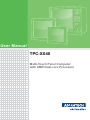
User Manual TPC-XX40 Multi-Touch Panel Computer with AMD Dual-core Processor Copyright The documentation and the software included with this product are copyrighted 2013 by Advantech Co., Ltd. All rights are reserved. Advantech Co., Ltd. reserves the right to make improvements in the products described in this manual at any time without notice. No part of this manual may be reproduced, copied, translated or transmitted in any form or by any means without the prior written permission of Advantech Co., Ltd. Information provided in this manual is intended to be accurate and reliable. However, Advantech Co., Ltd. assumes no responsibility for its use, nor for any infringements of the rights of third parties, which may result from its use. Acknowledgements Intel and Pentium are trademarks of Intel Corporation. Microsoft Windows and MS-DOS are registered trademarks of Microsoft Corp. All other product names or trademarks are properties of their respective owners. This Manual Covers the Following Models: TPC-1840 TPC-2140 TPC-XX40 User Manual Part No. 2003184000 Edition 1 Printed in Taiwan March 2013 ii Product Warranty (2 years) Advantech warrants to you, the original purchaser, that each of its products will be free from defects in materials and workmanship for two years from the date of purchase. This warranty does not apply to any products which have been repaired or altered by persons other than repair personnel authorized by Advantech, or which have been subject to misuse, abuse, accident or improper installation. Advantech assumes no liability under the terms of this warranty as a consequence of such events. Because of Advantech’s high quality-control standards and rigorous testing, most of our customers never need to use our repair service. If an Advantech product is defective, it will be repaired or replaced at no charge during the warranty period. For outof-warranty repairs, you will be billed according to the cost of replacement materials, service time and freight. Please consult your dealer for more details. If you think you have a defective product, follow these steps: 1. Collect all the information about the problem encountered. (For example, CPU speed, Advantech products used, other hardware and software used, etc.) Note anything abnormal and list any onscreen messages you get when the problem occurs. 2. Call your dealer and describe the problem. Please have your manual, product, and any helpful information readily available. 3. If your product is diagnosed as defective, obtain an RMA (return merchandize authorization) number from your dealer. This allows us to process your return more quickly. 4. Carefully pack the defective product, a fully-completed Repair and Replacement Order Card and a photocopy proof of purchase date (such as your sales receipt) in a shippable container. A product returned without proof of the purchase date is not eligible for warranty service. 5. Write the RMA number visibly on the outside of the package and ship it prepaid to your dealer. iii TPC-XX40 User Manual Declaration of Conformity CE This product has passed the CE test for environmental specifications when shielded cables are used for external wiring. We recommend the use of shielded cables. This kind of cable is available from Advantech. Please contact your local supplier for ordering information. FCC Class A Note: This equipment has been tested and found to comply with the limits for a Class A digital device, pursuant to part 15 of the FCC Rules. These limits are designed to provide reasonable protection against harmful interference when the equipment is operated in a commercial environment. This equipment generates, uses, and can radiate radio frequency energy and, if not installed and used in accordance with the instruction manual, may cause harmful interference to radio communications. Operation of this equipment in a residential area is likely to cause harmful interference in which case the user will be required to correct the interference at his own expense. Technical Support and Assistance 1. 2. 3. Visit the Advantech web site at http://support.advantech.com where you can find the latest information about the product. Contact your distributor, sales representative, or Advantech's customer service center for technical support if you need additional assistance. Please have the following information ready before you call: – Product name and serial number – Description of your peripheral attachments – Description of your software (operating system, version, application software, etc.) – A complete description of the problem – The exact wording of any error messages This product is intended to be supplied by a listed power supply complying with UL60950-1; rated from 18-32 VDC, minimum 2.5 A to 1.5 A. TPC-XX40 User Manual iv Safety Instructions 1. 2. 3. Read these safety instructions carefully. Keep this User Manual for later reference. Disconnect this equipment from any AC outlet before cleaning. Use a damp cloth. Do not use liquid or spray detergents for cleaning. 4. For plug-in equipment, the power outlet socket must be located near the equipment and must be easily accessible. 5. Keep this equipment away from humidity. 6. Put this equipment on a reliable surface during installation. Dropping it or letting it fall may cause damage. 7. The openings on the enclosure are for air convection. Protect the equipment from overheating. DO NOT COVER THE OPENINGS. 8. Make sure the voltage of the power source is correct before connecting the equipment to the power outlet. 9. Position the power cord so that people cannot step on it. Do not place anything over the power cord. 10. All cautions and warnings on the equipment should be noted. 11. If the equipment is not used for a long time, disconnect it from the power source to avoid damage by transient overvoltage. 12. Never pour any liquid into an opening. This may cause fire or electrical shock. 13. Never open the equipment. For safety reasons, the equipment should be opened only by qualified service personnel. 14. If one of the following situations arises, get the equipment checked by service personnel: The power cord or plug is damaged. Liquid has penetrated into the equipment. The equipment has been exposed to moisture. The equipment does not work well, or you cannot get it to work according to the user's manual. The equipment has been dropped and damaged. The equipment has obvious signs of breakage. 15. DO NOT LEAVE THIS EQUIPMENT IN AN ENVIRONMENT WHERE THE STORAGE TEMPERATURE MAY GO BELOW -20° C (-4° F) OR ABOVE 60° C (140° F). THIS COULD DAMAGE THE EQUIPMENT. THE EQUIPMENT SHOULD BE IN A CONTROLLED ENVIRONMENT. 16. CAUTION: DANGER OF EXPLOSION IF BATTERY IS INCORRECTLY REPLACED. REPLACE ONLY WITH THE SAME OR EQUIVALENT TYPE RECOMMENDED BY THE MANUFACTURER, DISCARD USED BATTERIES ACCORDING TO THE MANUFACTURER'S INSTRUCTIONS. The sound pressure level at the operator's position according to IEC 704-1:1982 is no more than 70 dB (A). DISCLAIMER: This set of instructions is given according to IEC 704-1. Advantech disclaims all responsibility for the accuracy of any statements contained herein. Caution! Danger of explosion if battery is incorrectly replaced. Replace only with the same or equivalent type recommended by the manufacturer. Dispose of used batteries according to the manufacturer's instructions. v TPC-XX40 User Manual TPC-XX40 User Manual vi Contents Chapter 1 General Information ............................1 1.1 1.2 1.3 Introduction ............................................................................................... 2 Packing List............................................................................................... 2 Specifications ............................................................................................ 3 1.3.1 System Kernel............................................................................... 3 1.3.2 I/O Ports........................................................................................ 3 1.3.3 Safety and Environment................................................................ 3 LCD Specifications.................................................................................... 4 Touchscreen Specifications ...................................................................... 4 Power ........................................................................................................ 4 I/O Ports Arrangement .............................................................................. 5 Figure 1.1 TPC-1840WP/2140WP- I/O Port Arrangement .......... 5 Panel Mounting ......................................................................................... 5 Figure 1.2 Panel Mounting........................................................... 5 Dimensions and Cutout............................................................................. 6 Figure 1.3 TPC-1840WP Dimensions.......................................... 6 Figure 1.4 TPC-2140WP Dimensions.......................................... 7 1.4 1.5 1.6 1.7 1.8 1.9 Chapter 2 System Setup .......................................9 2.1 2.3 System Setup.......................................................................................... 10 Figure 2.1 Unpack the Package ................................................ 10 Figure 2.2 Install CompactFlash Memory Card ........................ 10 Figure 2.3 Pin Definition of Power Connector............................ 11 Figure 2.4 Power Receptor........................................................ 11 Installing the Drivers................................................................................ 12 2.2.1 Installation of Touch Screen driver ............................................. 12 2.2.2 Installation of Watchdog driver.................................................... 12 2.2.3 Installation of graphic driver ........................................................ 15 2.2.4 Installation of LAN driver............................................................. 17 Cabinet Installation Guide ....................................................................... 18 3 Features in Windows Embedded .....19 3.1 3.2 3.3 Features in Windows Embedded ............................................................ 20 EWF ........................................................................................................ 20 HORM ..................................................................................................... 20 Appendix A Easy Installation ................................21 A.1 Easy Installation ...................................................................................... 22 2.2 Chapter Appendix B HDD assembly instructions and mSATA expansion25 B.1 B.2 HDD Assembly Instructions .................................................................... 26 mSATA expansion .................................................................................. 27 Appendix C UI Operating Process ........................31 vii TPC-XX40 User Manual C.1 UI Operating Process.............................................................................. 32 Table C.1: Status indicator table................................................ 32 Table C.2: Button code definition............................................... 37 Appendix D Notice ................................................. 39 D.1 Notice...................................................................................................... 40 Appendix E Comport pin definition ..................... 41 E.1 E.2 E.3 COM1/ COM2/ COM3: RS-232............................................................... 42 COM4(Option): RS-422/ 485 .................................................................. 42 RS-422/ 485 mode setting by BIOS........................................................ 43 TPC-XX40 User Manual viii Chapter 1 1 General Information 1.1 Introduction With brand-new ID design, TPC-1840/2140 series provide high resolution 18.5"/21.5" display and PCT multi-touch in 16:9 wide format. By embedding AMD T56E 1.65GHz processor with external APU, TPC-1840/2140 can support advanced graphical performance in more complex applications. Built-in function and home key button for greater user usability and operating safety. TPC-1840/2140 series also support miniPCIe slot for communication function expansion. The opening side cover is designed for easy maintenance of Cfast/HDD/Mini-PCIe components. The following are the key features: 18.5”WXGA / 21.5" Full HD TFT LED LCD display AMD dual-core T56E 1.65GHz with external APU, advanced graphical performance 16:9 wide screen with PCT multi-touch Built-in function and home key button used for intuitive UI Anti-scratch surface: 7H hardness Easy Maintenance of Cfast/HDD/Mini-PCIe components by opening side cover Support Mini-PCIe expansion slot Support HDMI for second display application HD Audio supports for alarm application Front LED indicator to show operating status NEMA4/IP65 compliant true flat screen Compact design with Die-cast Magnesium alloy front bezel 1.2 Packing List 12 x Panel Mount Clamps 12 x Panel Mount Screws 1 x 3 Pin Power Connector 1 x Power Indication Sticker 1 x Wire for Chassis Ground 1 x TPC Driver DVD 1 x Registration and Warranty Card 1 x Simplified Chinese Manual 1 x China ROHS list TPC-XX40 User Manual 2 Chapter 1 1.3 Specifications 1.3.1 System Kernel CPU: AMD G-series T56E 1.65GHz BIOS: AMI 32Mbit BIOS System Chipset: A50M FCH VGA: Integrated in A50M FCH Memory: 4GB SO-DIMM DDR3 SDRAM LAN: 10/100/1000Base-T x 2 Watchdog Timer: 1 ~ 255 sec (system) Expansion Slots: Full-size Mini PCI-E x 1 Storage: CFast slot x 1, 2.5" SATA HDD x 1(optional) OS Support: Microsoft® Win8/WES7P/XP/WES2009/WinCE 6.0/ Linux 1.3.2 I/O Ports 4 Serial Ports: RS-232 x 3, RS-422/485 x 1 2 USB Ports: compliant with USB 2.0 (Host) Video and Audio Ports: HDMI (Clone mode) x 1, Mic in & Line out x 1 1.3.3 Safety and Environment Safety FCC Class A CE certificated The front bezel is certified with IP65 Environment Operating Temperature: – 0 ~ 50°C (32 ~ 122°F) Storage Temperature: – -20 ~ 60°C (-4 ~ 140°F) Humidity: 40°C @ 10~95% relative humidity (non-condensing, test times: 48hrs) Vibration: 1 grms (5 ~ 500 Hz) with HDD, 2 grms (5 ~ 500 Hz) with CFast only 3 TPC-XX40 User Manual General Information 1.4 LCD Specifications TPC-1840WP TPC-2140WP Display Type WXGA LED LCD Full HD LED LCD Size (diagonal) 18.5" 21.5" Maximum Resolution 1366 x 768 1920 x 1080 Maximum Colors 16.7 M 16.7 M Viewing Angle 170°/160° 178°/178° Luminance (cd / m2) 300 300 Contrast Ratio 1000:1 5000:1 Backlight LED LED Note! There might be several bright or dark pixels on the LCD. This phenomenon is normal in today’s LCD manufacturing. 1.5 Touchscreen Specifications Touch Type: Projected Capacitive Base Glass Construction: Tempered glass Light Transmission: ≥88%(Measured by BYK-Gardner at 550nm, and the test method accorded to ASTM D1003) Controller: USB Interface 1.6 Power Input Voltage: – Typical - 24VDC – Swing Range - 18-32VDC (the fuse will become an open circuit if the input level exceeds 33VDC) Power Consumption: 35W (Typical) TPC-XX40 User Manual 4 Chapter 1 1.7 I/O Ports Arrangement The arrangement of the I/O ports is shown in Figure 1.1 1.8 Panel Mounting 1. 1. 2. 3. There is an adhesive waterproof gasket on the Mg front bezel. Make sure the waterproof gasket is in position before installing TPC into the panel opening. Install the TPC into the panel opening. Find the eight clamps and eight long screws in the accessory pack. Hook the clamps to the holes around the four sides of the bezel. Insert the screws into every clamp and fasten them. These screws will push the mounting panel and fix the unit. The suggested mounting panel thickness is less than 6 mm (0.236”). Figure 1.2 Panel Mounting 5 TPC-XX40 User Manual General Information Figure 1.1 TPC-1840WP/2140WP- I/O Port Arrangement 1.9 Dimensions and Cutout TPC-1840WP Weight: 8kg Dimensions (W x H x D): – 488.1 x 309.1 x 56.7 (19.2" x 12.2" x 2.2") Cutout: – 479.3 x 300.3 mm (19.2" x 12") 309.10 232.20 488.10 411.60 56.70 37.10 7 298.34 477.34 Figure 1.3 TPC-1840WP Dimensions TPC-XX40 User Manual 6 Chapter 1 TPC-2140WP Weight: 8.5kg Dimensions (W x H x D): – 580.7 x 355.3 x 56.7 (22.8" x 14" x 2.2") Cutout: – 551.1 x 345.7" (22.1" x 13.8") General Information 355.30 269.70 560.70 478.20 56.70 37.10 7 343.7 549.1 Figure 1.4 TPC-2140WP Dimensions 7 TPC-XX40 User Manual TPC-XX40 User Manual 8 Chapter 2 System Setup 2 2.1 System Setup You can easily get TPC started by following the below steps. 1. Unpack the TPC package. Check the packing list at the beginning of this manual to make sure all items have been included. 2. Figure 2.1 Unpack the Package Open side cover and then Install a CFast card containing Windows CE, Embedded Windows XP or another operating system. Figure 2.2 Install CompactFlash Memory Card Warning! It is suggested to turn OFF system power as you plug in or pull out the memory card, even though the CompactFlash memory is hot swappable. TPC-XX40 User Manual 10 Connect the power connector to the 24 VDC power lines. The power lines can either be of some power adapter or in-house power source. 4. 5. Figure 2.4 Power Receptor Plug the power lines into the system power receptor. Power on the system. 11 TPC-XX40 User Manual System Setup Figure 2.3 Pin Definition of Power Connector Chapter 2 3. 2.2 Installing the Drivers 2.2.1 Installation of Touch Screen driver TPC-1840 will use built-in PCT touch driver of OS If operating under WindowsXP SP3, Windows 7 and Windows 8. 2.2.2 Installation of Watchdog driver 1. Enter into Watchdog folder, double click AdvWDT icon, and then click "Next" under InstallShield Wizard window. 2. Select "Advantech [SCH311X] WDT” and click “Next” 3. Click “Install” TPC-XX40 User Manual 12 Click "Finish" to finish the installation 5. Select “Yes, I want to restart my computer now” and click “OK” 6. After installing Watchdog driver, a "Watchdog Service Configuration" icon will show in control panel. TPC-XX40 User Manual System Setup 13 Chapter 2 4. 7. Double click the "Watchdog Service Configuration" icon, and you can configure the Watchdog timer function. TPC-XX40 User Manual 14 Enter into TS folder, enter into” graphic driver for Windows 7" Driver folder and double click setup icon, and then click “Next” under setup wizard window. 2. Click “Install” 3. Select “Express” and click “Next” System Setup 1. Chapter 2 2.2.3 Installation of graphic driver 15 TPC-XX40 User Manual 4. Click “Accept” 5. Click “Finish” to finish the installation TPC-XX40 User Manual 16 Enter into TS folder, enter into “Ethernet driver for Windows 7" Driver folder and double click setup icon, and then click “Next” under setup wizard window. 2. Click ”Install” 3. Click “Finish” to finish the installation System Setup 1. Chapter 2 2.2.4 Installation of LAN driver 17 TPC-XX40 User Manual 2.3 Cabinet Installation Guide Follow the following steps to setup TPC-1840/2140 series, and please pay attention that Ground pin of TPC-1840/2140 series should be connected to earth ground. Under this circumstance, TPC-1840/2140 series could have the best performance such as EMI immunity, ESD immunity, Surge immunity and also system isolation. If TPC1840/2140 series is embedded in the cabinet, TPC-1840/2140’s ground, cabinet’s ground and earth ground should all be connected together. 1. Embed TPC-1840/2140 series into the cabinet. Step A: Connect the cabinet to earth ground. Step B: Embed null TPC-1840 series into the cabinet without any I/O cable and power. 2. System wiring Step A: Connect the cabinet to earth ground. Step B: Ensure that all cabinet has been grounded together. Step C: Connect the ground of the power supply to the cabinet. Step D: Connect the ground pin of TPC-1840/2140 series to the cabinet. Step E: Connect the I/O to the controller if needed. Step F: Connect the V+ and V- of power supply to TPC-1840/2140 series. While completing step A to F step by step, you can supply power to TPC-1840/2140 series now. TPC-XX40 User Manual 18 Chapter 3 3 Features in Windows Embedded 3.1 Features in Windows Embedded TPC product supports the embedded Windows platform. This section outlines the important features (EWF and HORM), that are provided in Windows XP embedded. 3.2 EWF EWF stands for Enhanced Write Filter. It provides an upper filter in the storage device driver stack that redirects disk write operations to volatile (RAM) or non-volatile (disk) storage. EWF protects a volume from write access. The benefits are as the following. Write-protect one or more partitions on your system. Enable read-only media, such as CD-ROM or flash, to boot and run. Prolong the lifespan of write-sensitive storage, such as CompactFlash. TPC-1840/2140 XPE provides EWF RAM-REG mode on system partition. All write to system partition will be redirected to RAM once this mode is enabled. This mode is manually enabled by customers after they finish all their changes on system such as installing their applications or adjusting system setting. Advantech provides a pair of utilities to operate EWF, OSLock andOSUnLock. Refer the training slide in the folder, file name is “Advantech XPe Add-one.pdf”. 3.3 HORM HORM stands for Hibernate Once Resume Many. In HORM environment, a single hibernation file is used to boot the system repeatedly. To set a HORM environment, please follow the steps below. Make sure EWF is disabled. You can run OSUnLock to disable EWF. Enable hibernation support: Run “power options” in control panel, and then select “Enable Hibernation” in hibernation pane. Enable EWF: Run OSLock, and then system reboot automatically. Open those software that customers want to directly use after system resume from hibernation. Hibernate via Advantech HORM utility: Click Start Menu->All Programs->Advantech->AdvWF HORM environment remains all along unless the following events occur: Run EWF commit command (ewfmgr c: -commit) and then reboot system. Select “Discard hibernation file” by clicking F8 when system is starting up. TPC-XX40 User Manual 20 Appendix A Easy Installation A A.1 Easy Installation With easy installation, a person can complete panel mount process by himself, just follow following steps: Step 1: Release the 2 screws in the top of TPC and the snap hook will arise. Step 2: And then release the 2 screws in the bottom of TPC TPC-XX40 User Manual 22 Step 4: Panel-mount installation complete Note! While using easy installation, the suggested mounting panel thickness is less than 2 mm (0.079"). When without easy installation, the suggested mounting panel thickness is less than 6 mm (0.236"). 23 TPC-XX40 User Manual Appendix A Easy Installation Step 3: Set TPC cross the cut-out hole and push it into the wall, the snap hook will hold the machine on the wall. TPC-XX40 User Manual 24 Appendix B B HDD assembly instructions and mSATA expansion B.1 HDD Assembly Instructions Step 1: Fix 2.5" HDD/SSD on the bracket, shown as follows: Step 2: Install the dampers in the bracket and fix by four screws. Step 3: Install HDD module into system and then cover back the side cover to finish. TPC-XX40 User Manual 26 Step1: Insert mSATA module to mini-PCIE slot as following picture shows: Step2: Change BIOS settings as following operations 1. Access BIOS setting page 2. Choose “chipset” page 27 TPC-XX40 User Manual Appendix B HDD assembly instructions and mSATA expansion B.2 mSATA expansion 3. Choose “South Bridge” and then enter 4. Choose “MINI Card/M-SATA” option and enter” 5. Choose “M-SATA” and enter 6. Press “ESC” to quit TPC-XX40 User Manual 28 Press “Save & Exit” option and enter Use “->” key 8. Choose “Yes” to complete setting 29 Appendix B HDD assembly instructions and mSATA expansion 7. TPC-XX40 User Manual TPC-XX40 User Manual 30 Appendix C C UI Operating Process C.1 UI Operating Process This section is to introduce how to operate HMI utility (GLToolBar), see the process below: 1. As you can find 2 function buttons in the lower right corner of front panel, represents “intelligent” key while represents “home” key. At the same time you can find status indicator show in following table: Table C.1: Status indicator table TPC-XX40 User Manual Indicator Status Green Power on Orange Stand by No light Off 32 One press Home Key-> Home – Back to desktop (default setting) Home - Execute Home-key App (Set up in setting page) 3. Long press Home Key-> Home - Long press to disable / enable touch function 33 TPC-XX40 User Manual Appendix C UI Operating Process 2. 4. One press Intelligent Key-> Intelligent - Advantech Intelligent Utility A. Quick start-> – Press “+” to add shortcut – Long press the icon to perform “right click” until an “X” mark appears in upper right corner to “delete” TPC-XX40 User Manual 34 – Setting - Home-key: Select an execute file to set up as "Home-key" App, in default path is to show “desktop” 35 TPC-XX40 User Manual Appendix C UI Operating Process B. Setting -> – Password confirmation for authority confirmation when first log in, default password is “1234” without input order to active. – Setting - Brightness: Brightness control from 10 to 100 percentages – Setting - Password: Change password function TPC-XX40 User Manual 36 Appendix C UI Operating Process C. System management-> – System information: – Self Diagnosis: Note!* TPC-1840/2140 also provides open button code as following definition for customer's configuration to their Apps/SW applications. The codes are defined from general keyboard input. Table C.2: Button code definition One press Long press Ctrl+Shift+Alt+I Ctrl+Shift+Alt+U Ctrl+Shift+Alt+H Ctrl+Shift+Alt+L I key(icon) H Key(icon) 37 TPC-XX40 User Manual TPC-XX40 User Manual 38 Appendix D Notice D D.1 Notice 1. RS-422/485 terminal impedance calculation: In order to improve transmission speed for big data and provide steady signal in long distance transmission of RS422/485, we'll add a terminal impedance that matches transmission line's impedance. Another key for correct signal transmission is that the Vfsb of receptor must be +/-0.2V. If Vfsb is under 0.2V, then it'll come out abnormal transmission result. The terminal impedance is the most important condition to maintain Vfsb above 0.2V. The RS422/485 I/O of TPC-1840 has been added pull high & pull low resistor, as shown in following diagram: When using RS422/485 port of TPC-1840/2140, please apply below formula to calculate terminal impedance to meet the standard. V fsb 0.2V V fsb 0.2V、Vcc 5V、Ra Rb 10 K V fsb Vcc( Rc / ( Ra Rc Rb )) TPC-XX40 User Manual 40 Appendix E E Comport pin definition E.1 COM1/ COM2/ COM3: RS-232 Pin Definition COM1/ COM2/ COM3 Pin Signal 1 NDCD 2 NRX 3 NTX 4 NDTR 5 GND 6 NDSR 7 NRTS 8 NCTS 9 NRI E.2 COM4(Option): RS-422/ 485 The serial port COM4 on the TPC-1840 series are adjustable by BIOS. It can be set to RS-422 or RS-485 mode. This port is designed with auto data flow control capability.In other words, the TPC-1840 series can automatically detect the data flow direction at this port when the two wired RS-485 communication is activated. Pin Definition COM 4 Pin Signal RS-422 RS-485 1 TX- D- 2 TX+ D+ 3 Rx+ – 4 Rx- – 5 GND GND 6 – – 7 – – 8 – – 9 – – TPC-XX40 User Manual 42 1. Enter into BIOS setup utility 2. Enter into Advanced tab and select Serial ports Configuration. 3. Select Serial Port4 Configuration (COM4) for RS-422/ 485 mode setting. 43 TPC-XX40 User Manual Appendix E Comport pin definition E.3 RS-422/ 485 mode setting by BIOS 4. The default setting is RS-422 mode. TPC-XX40 User Manual 44 Appendix E Comport pin definition TPC-XX40 User Manual 45 www.advantech.com Please verify specifications before quoting. This guide is intended for reference purposes only. All product specifications are subject to change without notice. No part of this publication may be reproduced in any form or by any means, electronic, photocopying, recording or otherwise, without prior written permission of the publisher. All brand and product names are trademarks or registered trademarks of their respective companies. © Advantech Co., Ltd. 2013