1
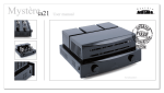
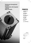
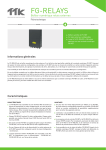
6SN3 SRPP Tube
Preamplifier User
Manual
ANALOG METRIC
www.analogmetric.com
[email protected]
Copyright ©2009 All Rights Reserved
[6SN3 SRPP TUBE PREAMPLIFIER USER MANUAL] Analog Metric
INTRODUCTION
Two dual triodes 6SN7 vacuum tubes are used for amplification in SRPP configuration.
The filaments are supplied by a low dropout voltage regulator LM1085. MKP filem
capacitors are used for signal paths. Symmetric layout is designed with matching
impedances between two signal paths and minimum parasitic, so it provides high
linearity, fast responses and low signal distortion. Also, this board has built-in full wave
rectification circuit and regulation circuit.
FEATURES
•
•
•
•
•
•
Two 6N3 (5670) vacuum tubes are configured in SRPP.
6Z4 uses as rectifier tube for high voltage supply.
A LM1085 IC is employed as regulator for tube filament supply.
Voltage Gain: 20dB
MKP film capacitors are used for signal paths.
Spaces are left for large reservoir decoupling capacitors.
www.analogmetric.com
Page 2
[6SN3 SRPP TUBE PREAMPLIFIER USER MANUAL] Analog Metric
•
•
•
•
Symmetric layout design between two channels.
Dedicated power and ground railings. Shortest signal paths with minimum parasitic.
Power requirement: two 200V AC (100mA) and two 6.3V AC (0.5A)
PCB dimension: 177mm x 107mm, 2.4mm thickness and 2oz copper.
PRECAUTIONS
•
•
•
•
•
Do not use any body parts to touch the metal parts of the kit after power up or power
off, since the high voltage capacitors may not fully discharge. It may cause serious
electric shock.
Use a power transformer with fuse (1-3A) socket to limit the supply current in case of
short circuit or incorrect assembly.
Double check the assembled components with the schematics.
Do not attempt the measure the voltage by multimeter with hand after power up. The
probes of the multimeter should be mounted by some stands to the points of the
measurement before switching on the power supply.
Turn off the power supply if you observe any smokes or hear strange sound coming
out from the transformer or board. If there is short circuit, the transformer will be
getting very hot shortly.
PROCEDURES
1. Solder all the components according to the schematic, BOM list, and the photo.
Notice to the polarity of the capacitors (C1-C4) and LED (D1 and D2). There is no
polarity of the thin film capacitors, so it can place in any directions.
2. Connector power supply to the board according to the following photo. It requires
two 200V AC (100mA) for J1, and two 6.3V AC (0.5A) for J2 and J3.
3. Turn on the power supply and then check the voltage at PIN 1 of tubes V1 and V2,
6.3V DC and the voltage at R2, 280V DC. If everything work property, the LED will
be led up, and also the tubes.
4. Enjoy it.
www.analogmetric.com
Page 3
[6SN3 SRPP TUBE PREAMPLIFIER USER MANUAL] Analog Metric
www.analogmetric.com
Page 4
[6SN3 SRPP TUBE PREAMPLIFIER USER MANUAL] Analog Metric
TESTING WAVEFORMS
If you have any problem
[email protected]
in
assembly,
please
contact
us
by
email
to
www.analogmetric.com
Page 5