1
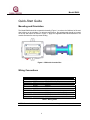
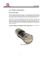
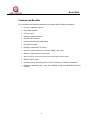
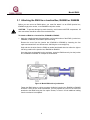
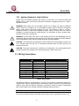
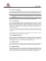
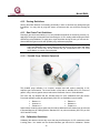
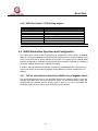
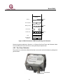
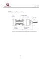
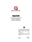
Model IR400 Infrared Point Detector for Hydrocarbon Gas Applications The information and technical data disclosed in this document may be used and disseminated only for the purposes and to the extent specifically authorized in writing by General Monitors. Instruction Manual 12-10 General Monitors reserves the right to change published specifications and designs without prior notice. MANIR400 Part No. Revision MANIR400 C/12-10 Model IR400 This page intentionally left blank. ii Model IR400 Table of Contents TABLE OF FIGURES ..................................................................................................................IV TABLE OF TABLES....................................................................................................................IV QUICK-START GUIDE................................................................................................................. 2 1.0 INTRODUCTION .................................................................................................................... 4 1.1 1.2 1.3 Protection for Life .......................................................................................................................4 Special Cautions and Warnings.................................................................................................4 Installation, Operation, and Maintenance ..................................................................................4 2.0 PRODUCT DESCRIPTION..................................................................................................... 5 3.0 INSTALLATION...................................................................................................................... 7 3.1 3.2 3.3 3.4 Attaching the IR400 to a Junction Box, IR4000S or IR4000M...................................................8 Mounting Instructions .................................................................................................................9 Wiring Connections ..................................................................................................................11 Applying Power ........................................................................................................................13 4.0 OPERATION AND CONFIGURATION ................................................................................ 15 4.1 4.2 4.3 4.4 4.5 Zeroing, Gas Check Tests, and Calibration .............................................................................15 IR400 Stand-alone Operation and Configuration.....................................................................18 HazardWatch Mode .................................................................................................................21 Gas Check Mode .....................................................................................................................21 Detector Response Time .........................................................................................................21 5.0 MAINTENANCE ................................................................................................................... 23 5.1 5.2 5.3 5.4 Developing a Maintenance Schedule ......................................................................................23 Gas Checks, Zeroing and Recalibration ..................................................................................23 Cleaning and Lubricating the IR400 and IR4000 Units............................................................24 Storage.....................................................................................................................................24 6.0 TROUBLESHOOTING ......................................................................................................... 25 7.0 MODBUS INTERFACE ........................................................................................................ 27 8.0 CUSTOMER SUPPORT ....................................................................................................... 28 9.0 APPENDIX............................................................................................................................ 29 9.1 9.2 9.3 Warranty...................................................................................................................................29 Principle of Operation...............................................................................................................30 Specifications ...........................................................................................................................31 iii Model IR400 9.4 9.5 9.6 9.7 Environmental Specifications...................................................................................................34 Communications ......................................................................................................................34 Engineering Documentation.....................................................................................................35 Ordering Information ................................................................................................................36 Table of Figures Figure 1: IR400 with Junction Box.......................................................................................................................... 2 Figure 2: Wiring Diagram from IR400 to Control Equipment.................................................................................. 3 Figure 3: Model IR400 ............................................................................................................................................ 5 Figure 4: Model IR400 with a junction box ............................................................................................................. 8 Figure 5. IR400 Mounting Dimensions .................................................................................................................. 9 Figure 6: IR400 with Junction Box........................................................................................................................ 13 Figure 7: Wiring Diagram from IR400 to Control Equipment................................................................................ 14 Figure 8. IR400 Zero Switch / LED During Zeroing and Calibration .................................................................... 19 Figure 9. IR400 optical window locations ............................................................................................................ 24 Figure 10: Outline and Dimensional Drawing, IR400, inch measurements.......................................................... 35 Table of Tables Table 1: Wiring Chart.............................................................................................................................................. 2 Table 2: Wiring Chart............................................................................................................................................ 11 Table 3: IR400 without HART option .................................................................................................................... 17 Table 4: IR400 with HART option ......................................................................................................................... 17 Table 5: GM Locations.......................................................................................................................................... 28 Table 6: Analog Current Output............................................................................................................................ 33 Table 7: Maximum Distance between IR400 and Power Source......................................................................... 33 Table 8: Maximum Distance between IR400 and 500-Ohm Input Impedance..................................................... 33 iv Model IR400 Quick-Start Guide Mounting and Orientation The Model IR400 should be mounted horizontally (Figure 1) to reduce the likelihood of dirt and dust build-up on the windows. For optimum performance, the splashguards should be located on the top and bottom as shown in Figure 1. Apply the supplied thread lubricant/sealant to all conduit entries before use to prevent binding. Figure 1: IR400 with Junction Box Wiring Connections TERMINAL 1 2 3 4 5 6 7 8 9 10 WIRE COLOR BLACK GREEN RED WHITE BLUE WHT/BLU BROWN - SIGNAL COM FIELD GROUND (FG) +24 V 4-20 mA MOD1+ MOD1 CAL MOD2+ (no connection for IR400) MOD2 - (no connection for IR400) No Connection Table 1: Wiring Chart NOTE: Power should remain disconnected until all other wiring connections are made. 2 Model IR400 Power Connections To supply power to the IR400, connect the red lead from the IR400 to the +24 VDC terminal on the power supply. Connect the black lead from the IR400 to the power supply Common. Refer to the manual of the power source being used, for more detailed instructions. NOTE: If the Model IR400 is being used with a +24 VDC power supply and an industrial analog to digital (A/D) converter, then the negative supply (Common) of all three must be connected. Applying Power Before applying power to the system for the first time, all wiring connections should be checked for correctness. Upon initial power-up or after a fault condition has been corrected, the unit will enter a start-up mode for 120 seconds before returning to normal operation (analog output will be 0 mA). After power is applied, the IR400 should be allowed to stabilize for approximately 60 minutes while the unit attains the proper operating temperature. After stabilization, it is recommended that the IR400 be zeroed, per the procedure in section 4.1 (step 1 only). A gas check should then be performed to ensure that the unit is operating properly. Use the General Monitors Gas Check Kit (P/N 32548) to perform this check. Figure 2: Wiring Diagram from IR400 to Control Equipment The instrument is now ready to operate. Please further consult this manual for more information on the instrument’s many features. 3 Model IR400 1.0 Introduction 1.1 Protection for Life General Monitors’ mission is to benefit society by providing solutions through industry-leading safety products, services and systems that save lives and protect capital resources from the dangers of hazardous flames, gases and vapors. The safety products you have purchased should be handled carefully and installed, calibrated and maintained in accordance with this instruction manual. Remember, these products are for your safety. 1.2 Special Cautions and Warnings This instruction manual includes numerous cautions and warnings that are included to prevent injury to personnel and prevent damage to equipment. WARNING: TOXIC, COMBUSTIBLE, AND FLAMMABLE GASES AND VAPORS ARE VERY DANGEROUS. USE EXTREME CAUTION WHEN THESE HAZARDS ARE PRESENT. 1.3 Installation, Operation, and Maintenance Before power up, verify wiring, terminal connections and stability of mounting for all integral safety equipment. Proper system operation should be verified by performing a full, functional test of all component devices of the safety system, ensuring that the proper levels of alarming occur. Fault/malfunction circuit operation should be verified. Periodic testing/calibrating should be performed per the manufacturer’s recommendations and instructions. When testing produces results outside of the manufacturer’s specifications, re-calibration or repair/replacement of the suspect device(s) should be performed as necessary. Calibration intervals should be independently established through a documented procedure, including a calibration log maintained by plant personnel, or third party testing services. 4 Model IR400 2.0 Product Description General Description The Model IR400 infrared (IR) point detector is a microprocessor-based combustible gas detector, is calibrated at the factory and needs no routine field calibration. Applying a test gas to the unit can check the sensitivity of the IR400. It is also relatively maintenance free, requiring only a periodic cleaning of the windows and re-zeroing to ensure dependable performance. The IR400 continuously monitors combustible gases in the lower explosive limit (LEL) range and provides a 4 to 20 mA analog signal proportional to the 0 to 100% LEL concentration. Gas calibration is available to LEL values defined by ISO 10156/NFPA 325 and IEC 61779-1. A Modbus communications interface is also provided for informational / programming purposes. Sensor data and status information from the IR400 can be transmitted to a variety of General Monitors’ readout units. The IR400 operates from an unregulated +24 volt DC supply, which can be supplied by the customer, or is supplied by General Monitors’ Model DC130 readout units. Figure 3: Model IR400 5 Model IR400 Features and Benefits This is a partial list of features and benefits for the Model IR400 infrared point detector: • No routine calibration required • Fail-to-safe operation • 4-20 mA output • Modbus communications link • Optional HART interface • Heated optics eliminate condensation • Dirty optics indication • Reading not affected by air velocity • Immune to typical poisons (e.g. silicones, halides, lead, sulfur) • Works in oxygen deficient environments • Able to operate in constant hydrocarbon environment without adverse effects • IP66 & TYPE 4X rating • Interfaces directly with existing DC110, DC130 controllers & TA102A trip amplifiers • Expanded capabilities when used with IR4000S Single and IR4000M Multi-Point monitors 6 Model IR400 3.0 Installation Receipt of Equipment All equipment shipped by General Monitors is packaged in shock absorbing containers, which provide considerable protection against physical damage. The contents should be carefully removed and checked against the packing list. If any damage has occurred or there is any discrepancy in the order, please notify General Monitors as soon as possible. All subsequent correspondence with General Monitors must specify the equipment part number and the serial number. Detector Location Considerations There are no standard rules for detector placement, since the optimum detector location varies with the application. The customer must evaluate conditions at the facility to make this determination. If practical, the Model IR400 infrared point detector should be easily accessible for occasional integrity checks. The unit should be mounted horizontally so that dirt and dust do not build-up on the windows. Although the IR400 is RFI resistant, it should not be mounted close to radio transmitters, high magnetic or electrical fields or similar equipment. NOTE: The Model IR400 cannot detect hydrogen (H2) gas. Some other factors to consider when selecting a detector location: • Emission temperature and vapor density of the gas. The IR400 should be located near the floor for gas vapors that are heavier than air. • Do not locate the IR400 in areas that exceed the maximum operating temperature of the unit, such as gas turbine exhaust. • Locate the IR400 where prevailing air currents contain the maximum concentration of gas. • Locate the IR400 as near as possible to the likely source of a gas leak. • Observe the temperature range of the IR400 and locate the unit away from concentrated sources of heat or light. • Mount the IR400 away from sources of excessive vibration. WARNING: Each IR400 is completely tested at the factory. However, a complete system checkout is required upon initial installation and start-up to ensure system integrity. NOTE: The Model IR400 is factory calibrated and needs no routine calibration. However, if the IR400 is to be installed at altitudes greater than 1000 ft (300m), it must be re-calibrated on-site (Section 4.1). 7 Model IR400 3.1 Attaching the IR400 to a Junction Box, IR4000S or IR4000M Before you can mount an IR400 device, you must first attach it to an IR400 junction box, IR4000S single point monitor, or an IR4000M multi-point monitor. CAUTION: To prevent damage by static electricity, avoid contact with PCB components. All wire connections should be made to the terminal blocks. To Attach an IR400 to a Junction Box, IR4000M or IR4000S 1. Apply the supplied thread lubricant/sealant to all conduit entries of the IR400, junction box, IR4000M, or IR4000S, as needed to prevent binding. Remove the cover from the junction box, IR4000M or IR4000S by loosening the four captive screws with a 5 mm Allen wrench, and lifting the cover straight up. Strip and trim the wires from the IR400 as needed and thread them into either the right or left wiring conduit of the junction box, IR4000M or IR4000S. Once the wires are threaded into the enclosure, screw the IR400 securely into the junction box, IR4000M or IR4000S. An example is shown below. Figure 4: Model IR400 with a junction box Fasten the IR400 wires to a wiring connector inside the junction box, IR4000M or IR4000S enclosure. Once the two units are attached, you may replace the cover on the enclosure attached to the IR400 using the four captive screws, or leave it off until additional cabling from the enclosure is completed. 8 Model IR400 3.2 Mounting Instructions The IR400 is mounted using the bolt holes on an attached junction box, IR4000M or IR4000S enclosure. The IR4000M(S) is often mounted remote from the IR400 units, in order to locate it within easy reach and at eye level. 3.2.1 Mounting an IR400 with an Attached Enclosure The following figure shows the overall and mounting dimensions for the Model IR400 with an attached junction box / IR4000M(S) enclosure. MODEL IR4000M P/N 32580 0518 0539 CALIBRATION PROCEDURE 1. HAVE DETECTOR IN CLEAN AIR 2. APPLY MAGNET, AND WAIT FOR "AC" ON DISPLAY 3. REMOVE MAGNET, WHEN d# IS DISPLAYED, APPLY MAGNET TO SELECT DETECTOR # 4. REMOVE MAGNET, FLASHING "AC" IS DISPLAYED 5. WHEN "AC" IS STEADY, APPLY GAS 6. WHEN GAS IS DETECTED, "CP" IS DISPLAYED 7. WHEN CALIBRATION IS COMPLETE, "CC" IS DISPLAYED 8. REMOVE GAS ALARM LED WARN LED S/N CONFIG MAN YEAR OF CONSTRUCTION Figure 5. IR400 Mounting Dimensions 9 Model IR400 To Mount the IR400 The IR400 must rest horizontally to reduce the possibility of dirt and dust building up on the lens. • The open slots of the gas passage must be straight up and down for the gas to rise up and through the unit. • If the detector is installed with the metal section blocking the gas flow, it will slow down the detector’s response. Mount the attached junction box or IR4000M(S) enclosure using the two bolt holes. NOTE: There is also a duct mounting kit available from General Monitors with separate instructions. 3.2.2 Cabling Safety Notices CAUTION: The Model IR400 detector and Model IR4000M(S) monitor system contain components that can be damaged by static electricity. Special care must be taken when wiring the system to ensure that only the connection points are touched. WARNING: Under NO circumstances should equipment be connected or disconnected when under power. This is contrary to hazardous area regulations and may also lead to serious damage to the equipment. Equipment damaged in this manner is not covered under warranty. 3.2.2.1 European Union (EU) Approved Cable Armor and Screens Interconnecting cables must have an overall screen or screen and armor. Cable BS5308 Part 2, Type 2, or equivalent is suitable. Note that the terms ‘screen’ and ‘shield’ are equivalent for the purpose of this manual. The cable armor must be terminated in a suitable cable gland at the detector to ensure a positive electrical connection. 3.2.2.2 Cable Termination in Non-Hazardous Areas • The cable armor must be connected to safety earth in the safe area. • The cable screen (drain wire) must be connected to an instrument earth in the safe area. • The power supply 0V return must be connected to an instrument earth in the safe area. • The interconnecting cables should be segregated from power and other noisy cables. Avoid proximity to cables associated with radio transmitters, welders, switch mode power supplies, inverters, battery chargers, ignition systems, generators, switch gear, arc lights and other high frequency or high power switching process equipment. • In general, maintain separation of at least 1 meter between instrument and other cables. Greater separations are required where long parallel cable runs are unavoidable. Avoid running instrument cable trenches close to lightning conductor earthing pits. • Complete all cable insulation testing before connecting the cable at either end. 10 Model IR400 3.2.3 Applying Sealants to Conduit Entries Please keep the following warnings and cautions in mind when you install the IR400 and IR4000 units, to make sure that the equipment maintains the appropriate seals for a Class I hazardous location. WARNING: Each conduit run from an IR400 junction box or display unit within a hazardous location (and from a hazardous to a non-hazardous location) must be sealed so that gases, vapors, and/or flames cannot pass beyond the seal. The purpose of seals in a Class I hazardous location is to prevent the passage of gases, vapors, or flames from one electrical installation to another through the conduit system. For information on Class I location seals, see NEC Articles 501-5 and 500-3d. WARNING: Unused cable entry holes in each IR400 junction box and IR4000M(S) must be sealed with approved explosion-proof stopping plugs. Red caps supplied by General Monitors are for dust protection only, and must not be left on the unit when installed. CAUTION: Acetic acid will cause damage to metal components, metal hardware, ceramic ICs, etc. If damage results from the use of a sealant that contains acetic acid (RTV silicone), the warranty will be void. CAUTION: To prevent corrosion due to moisture or condensation, it is recommended that the conduit connected to the display unit housing be sealed or contain a drain loop. 3.3 Wiring Connections WIRE 1 2 3 4 5 6 7 8 9 10 WIRE COLOR BLACK GREEN RED WHITE BLUE WHT/BLU BROWN - SIGNAL COM FIELD GROUND (FG) +24 V 4-20 mA MOD1+ MOD1CAL MOD2+ (no connection for IR400) MOD2 - (no connection for IR400) No Connection Table 2: Wiring Chart The IR400 operates on nominal power of +24 VDC. The customer must provide primary DC voltage power, unless a General Monitors readout/relay display module with an internal power supply is used. Since the IR400 is designed to continuously monitor for leaks of hydrocarbon gas, a power switch is not included to prevent accidental system shut down. NOTE: Power should remain disconnected until all other wiring connections are made. The maximum distance between the IR400 and the power source is specified in Section 9.3.3. 11 Model IR400 3.3.1 Power Connections To supply power to the Model IR400 connect the red lead from the IR400 to the +24 VDC terminal on the power supply. Connect the black lead from the IR400 to the power supply Common. Refer to the manual of the power source being used, for more detailed instructions. NOTE: If the IR400 is being used with a +24 VDC power supply and an industrial analog to digital (A/D) converter, then the negative supply (Common) of all three must be connected. An internal diode protects the system in the event of inadvertent supply reversal. 3.3.2 4- 20 mA Output A 4 to 20 mA output signal is provided by the Model IR400 and can be sent to a General Monitors’ readout/relay display module or any industrial device that can accept a 4 to 20 mA signal for computer based multi-point monitoring. The Analog Output connection provides a signal for use in displaying current LEL readings, special operation or fault conditions. The maximum distance between the IR400 and the device connected to the Analog Output signal is specified in Section 9.3.5. To access the 4-20 mA signal, connect the white lead from the IR400 to the signal-in terminal of the input unit. Refer to the manual of the display or other device being used for detailed instructions. Connect the black lead from the IR400 to the device Common. The Common connection serves both the analog signal and the power connections. 3.3.3 Dual Modbus Interface To access the Modbus (Modbus-RTU) interface, connect the blue lead from the IR400 to the Modbus (+) terminal and the blue/white lead to the Modbus (-) terminal on the customer’s Modbus capable device. For a description of the data available from the IR400 and the programming interface, please refer to the separate IR400 Modbus manual. 3.3.4 HART Interface A standard HART interface is available which provides a digital data channel at 1200 baud over the 4-20 mA current loop. See the IR400 HART Manual Addendum for additional information. 3.3.5 Magnetic Switch The IR400 also provides a lead for connecting a +24 VDC powered magnetic switch. The brown lead from the IR400 must be connected to the powered side of the switch so that when the switch is activated, the brown lead is grounded. General Monitors can supply a junction box with an integral magnetic switch to ease the connection of the IR400 in the field (Figure 6). 12 Model IR400 3.4 Applying Power Before applying power to the system for the first time, all wiring connections should be checked for correctness. Upon initial power-up or after a fault condition has been corrected, the unit will enter a start-up mode for 120 seconds before returning to normal operation (Analog output will be 0 mA for a non-HART configuration and 1.25 or 3.5 mA for a HART configuration). After power is applied, the IR400 should be allowed to stabilize for approximately 60 minutes while the unit attains the proper operating temperature. After stabilization, it is recommended that the IR400 be zeroed, per the procedure in Section 4.1 (step 1 only). A gas check should then be performed to ensure that the unit is operating properly. Use the General Monitors gas check kit (P/N 32548-x) to perform this check. If the unit does not respond properly, calibrate per the procedure in Section 4.1.4 (steps 1-4). • When connecting the IR400 to a safety system, the +24 VDC (red) wire should be the last wire connected and first wire disconnected when removing the unit to protect the system from shorting. • If the analog (4-20 mA) output is not used, then the white signal wire must be connected to ground to prevent a fault condition. Figure 6: IR400 with Junction Box 13 Model IR400 Figure 7: Wiring Diagram from IR400 to Control Equipment 14 Model IR400 4.0 Operation and Configuration The methods used to operate and configure the IR400 will vary depending on whether you are using the IR400 as part of an IR4000M monitoring system, or as a stand-alone unit attached to a junction box and control room devices, or to an IR4000S. Separate instructions are provided in this chapter for each situation. • If your IR400 is part of an IR4000M system, you can operate and configure both the IR400 and the IR4000 using the IR4000 menu options and LED display. You can also send Modbus or HART commands to the IR4000 from connected control room devices, to perform all the menu-driven functions, plus additional ones. • If your IR400 is a stand-alone unit attached to a junction box, you can use the magnetic switch attached to the junction box for zeroing and calibration. You can also send Modbus or HART commands to the IR400 from control room devices to perform zero, calibration, gas checks and configuration tasks. • If your IR400 is a stand-alone unit attached to an IR4000S display device, then you can use the IR4000S menus for operation and configuration. NOTE: This chapter describes how to use the junction box magnetic switch for stand-alone IR400 operation; the IR4000 manual describes how to use the IR4000 menus for IR400 system operation and configuration. 4.1 Zeroing, Gas Check Tests, and Calibration Each IR400 is calibrated at the factory. However they will need occasional zeroing as well as gas check tests and calibration after initial installation to make sure they are working properly. Before zeroing or calibration, always check that the optics path is clear and the windows are clean. These are the most important operations to ensure that the IR400 is measuring accurately. Depending on your system configuration, you can use menus, Modbus/HART commands or magnetic switch selection to initiate zeroing, gas checks and calibration, as described later in this chapter. Some general guidelines are provided here that are useful no matter what method is used. NOTE: The IR400 is factory calibrated and needs no initial calibration. However, if the unit is to be installed at altitudes greater than 1000 ft (308 m), it must be re-calibrated on-site. NOTE: Entering Gas Check, Zeroing, or Calibration mode sends a 1.5 mA output signal that disables the IR4000M and IR4000S Warning and Alarm relay circuits. 4.1.1 Using Zero Air If you suspect that combustible gasses are present, it is necessary to purge the sensor environment with zero air before zeroing the unit, starting the gas check, or starting calibration. 15 Model IR400 4.1.2 Zeroing Guidelines Zeroing the IR400 detector is necessary periodically in order to eliminate any background gas fluctuations. You may wish to purge the sensor environment with zero air before zeroing the unit. 4.1.3 Gas Check Test Guidelines Running a gas check test enables you to verify whether the detector is functioning correctly, by applying a known gas concentration and monitoring the % LEL reading while keeping the alarm and warning relays disabled. To apply gas or a gas simulation during the test, you can use the General Monitors gas check kit with portable purge calibrator equipment. NOTE: You cannot run a gas check test from an FMD or IR4000S attached to an IR400. The FMD and IR4000S have a relay inhibit mode that will turn off the Warn and Alarm relay but the current loop will still transmit the gas concentration level. This could cause alarms on control room equipment. 4.1.3.1 Portable Purge Calibrator Equipment The portable purge calibrator is a compact, accurate and safe system containing a nonexplosive gas concentration. The lecture bottle is filled with a standard 50% LEL mixture of gas/air. Using a known gas/air mixture reduces the likelihood of error in field calibration. The hose and cup adapter that are included allow for quick calibrations and gas checks. Pre-mixed calibration gases at approximately 50% LEL are available in lecture bottles. • • • • • • ButaneC4H10 HexaneC6H14 PentaneC5H12 EthaneC2H6 MethaneCH4 PropaneC3H8 Spare bottles containing these gases may be ordered. Methane lecture bottles may be returned to General Monitors for refilling with the standard 2.5% by volume methane (50% LEL per ISO 10156 and NFPA 325). 4.1.4 Calibration Guidelines Calibrating the detector corrects any errors that may be affecting the % LEL measurement that is taking place. You should use the General Monitors gas check kit for calibration. Section 16 Model IR400 4.1.3.1 describes the gas check kit equipment in more detail. You may need to calibrate the IR400 detector under several circumstances. • If the gas check test indicates that the detector needs adjustment. • If you are reconfiguring the IR400 to detect a different type of gas. • If you are moving the detector to a higher altitude location (every 1000 feet difference in altitude requires recalibration). General Monitors configures the IR400 with 3 calibration input options: magnetic switch (default), manual solenoid, and automatic remote gas calibration device (ARGC). To use the manual solenoid or ARGC, purchase a factory configured IR400 or change the calibration input via Modbus or HART. 4.1.5 IR400 analog output (AO) interpretation Current Level (mA) 0 1.5 2 4 – 20 20.1 – 21.7 Meaning Startup mode and critical fault for non HART unit Zero, Calibration and Gas Check Mode Non critical fault 0 – 100% LEL or % by Volume Over range Table 3: IR400 without HART option Current Level (mA) 0 1.25 1.5 2 3.5 4 – 20 20.1 – 21.7 Meaning Startup mode and critical fault for non HART unit Startup mode and critical fault if current range is low Zero, Calibration and Gas Check Mode Non critical fault All faults and startup if unit is configured with current range set to “high” 0 – 100% LEL or % by Volume Over range Table 4: IR400 with HART option 17 Model IR400 4.1.6 IR400 Zero Switch / LED flashing patterns Flashing Pattern (ms) Description 1000 on, 1000 off 950 on, 50 off 100 on, 400 off 500 on, 1000 off 980 on, 20 off 100 on, 100 off Zero Zero complete, calibration pending Calibration, apply gas Gas present, calibration in progress Calibration complete; remove gas Fault NOTE: This table is for Zero Switch / LED calibration input configurations only. 4.2 IR400 Stand-alone Operation and Configuration The IR400 does not have built-in operation and configuration menus without an IR4000. However, zeroing and calibration can be accomplished using the Zero (magnetic) Switch / LED on the junction box that is directly attached to the IR400. You should ‘zero’ the Model IR400 detectors occasionally to eliminate any background gas fluctuations. Calibration is necessary if gas check readings show the unit is reading inaccurately. In addition, many operational functions are available using the Modbus/HART interface from a control room device, as described in separate General Monitors’ manuals (available from our website). 4.2.1 To Zero and Calibrate a Stand-alone IR400 Using a Magnetic Switch This procedure describes how to use the IR400 junction box magnetic switch to zero and calibrate the IR400. Once zeroing or calibration begins, the alarm and warning relays are automatically kept disabled, and the analog signal is held at 1.5 mA. As you follow the procedure steps, refer to the figure shown below for the LED indicator. 18 Model IR400 2 Seconds Zeroing Step 1 Zero Complete Waiting for Gas Step 2 Gas Present No Gas, Error Step 3 Fault Re-Calibration Complete Figure 8. IR400 Zero Switch / LED During Zeroing and Calibration Review the general guidelines in Section 4.1 on Zeroing, Gas Check Tests, and Calibration. Make sure the windows are clean and there is nothing blocking the optical beam. 4.2.2 Zero Only Calibration The junction box used with the IR400 is fitted with a zero switch which eliminates any background gas fluctuation. Zero Switch 19 Model IR400 Zero the Unit. Apply the General Monitors magnet that was included with the unit to the Zero Switch / LED for approximately three seconds. The LED in the switch will light to show proper placement. • Remove the magnet and the LED will flash on for one second and off for one second to indicate that the unit is attaining a zero value (Zeroing in the figure). • When the unit has finished zeroing, the LED will turn on and flash off quickly once per second for 30 seconds (Zero Complete in Figure 8). NOTE: If an error occurs during the zeroing/calibration sequence, the LED will flash on and off rapidly (Fault). 4.2.3 Full Span Calibration If a full span calibration is required, a zero calibration must first be performed to eliminate any background gas fluctuation. When the zero calibration is complete, a full span calibration may optionally be performed. 1. Zero the Unit. Apply the General Monitors magnet that was included with the unit to the Zero Switch / LED for approximately three seconds. The LED in the switch will light to show proper placement. • Remove the magnet and the LED will flash on for one second and off for one second to indicate that the unit is attaining a zero value (Zeroing in the figure). • When the unit has finished zeroing, the LED will turn on and flash off quickly once per second for 30 seconds (Zero Complete in Figure 8). NOTE: If an error occurs during the zeroing/calibration sequence, the LED will flash on and off rapidly (Fault). 2. Return to Normal Operation or Start Calibration. If the magnet is not applied again, the unit will return to normal operation. To continue on and calibrate, apply the magnet again and the unit will enter the calibration mode. The LED will flash off quickly once every half-second while the unit is waiting for gas to be applied (Waiting for Gas). 3. Apply Gas. Apply a 50% LEL gas using a Gas Check Kit with portable purge calibrator equipment (or 50% by volume of the gas being detected in nitrogen for units designed for monitoring 0 to 100% by volume). • When the unit detects the gas, the LED will flash on for a half second every one and one-half seconds (Gas Present). • If the unit does not detect the gas, the LED will flash off quickly once every half-second while the unit is still waiting for gas to be applied (No Gas Error). • Once calibration has been completed, the LED will turn on and flash off once every second (Calibration Complete). 4. Return to Normal Operation. Remove the gas and the unit will return to normal operation once the gas has fallen below 5% of full scale. 20 Model IR400 4.3 HazardWatch Mode The IR400 is compatible with the General Monitors HazardWatch System and can be calibrated via the system interface for HazardWatch. To support calibrations initiated in HazardWatch, the IR400 must be configured in the HazardWatch Mode. This mode prevents aborted calibrations from being recorded as successful calibrations and ensures accurate logging in the HazardWatch System. To use this feature, purchase a HazardWatch-configured IR400 or change the mode via Modbus. See the Modbus manual available from the General Monitors website for Modbus commands. 4.4 Gas Check Mode 1. Send Modbus or HART gas check command. 2. When the unit enters gas check mode, AO will be kept at 1.5 mA. Apply a 50% LEL gas using a gas check kit with portable purge calibrator equipment. NOTE: If the manual solenoid calibration input is configured, send the Modbus or HART command to turn on the solenoid. 3. Once the detector is placed in gas check mode and the gas is applied, monitor the % LEL reading for the detector to see if it is functioning properly using the FMD or IR4000S display or Modbus/HART commands. When the reading is stabilized, it should be 50% LEL if the gas from the check kit is applied. 4. Remove the gas. NOTE: If the manual solenoid calibration input is configured, send the Modbus or HART command to turn off the solenoid. The unit will return to normal operation when the concentration drops below 5% full-scale. Since the IR400 zeros before calibrating, you must remove the gas completely before going to calibration mode. 4.5 Detector Response Time A valid response time of a gas detector must take into account a static gas presence as it occurs in the field with a gas leak. Tests performed on site use a flow method to verify detector function only as gas enters the optical path, with its splashguard in place, slowly. With regard to the specified time response stated on page 3 of the manual, this specification is obtained by testing the gas detector, with a splashguard, in accordance with CSA performance requirements. A chamber is filled with a known concentration of gas (static) and the IR400 is then exposed to the gas. This method is defined by the approval agencies and allows us to fill instantaneously the optical path of detector to achieve the stated response times for the IR400. It is not practical to perform this type of test in the field since a potentially explosive gas (100% LEL) is used. 21 Model IR400 T response times: According to CSA C22.2, T50 equals time to 50% of full-scale meaning 50% LEL and T90 which is 90% of the final reading. CSA C22.2 Section 6.9 states: Beginning with the gas sensing element in clean air it shall be suddenly exposed to a prepared mixture of gas in air having a concentration corresponding to 100% of the full scale gas concentration. From the instant of exposure to this gas mixture the instrument shall respond to provide an indication within the time specified as follows: 50% of full scale gas concentration in 10 sec, and 90% of maximum indicated gas concentration in 30 sec. The products offered by GM are not for the purpose of testing T response time, but as a method to allow a user to check that the unit is responding to gas and that final response is within tolerance. The products offered by GM are not for the purpose of testing T response time, but as a method to allow a user to check that the unit is responding to gas and/or that final response is within tolerance. If it’s required to demonstrate a reading of 50% LEL at site this can be achieved using the calibration cup, however it should be noted that you need to apply the test gas for approximately three minutes to get a reading of 50% LEL. This time is due to the ambient air located in the optical path of the detector having to be replaced progressively by the test gas. This replacement of ambient air is quicker at the beginning but longer for the last percentage because it is linked to the slow replacement of air dilution by the test gas. This test is only to indicate a gas level of 50% LEL within the calibration cup and is not a reflection of the response time of the detector. 22 Model IR400 5.0 Maintenance The Model IR400 is calibrated at the factory and is fail-to-safe; once it is correctly installed and calibrated upon start-up, it requires little maintenance other than periodic cleaning, gas checks, zeroing and recalibration to ensure system integrity. Integrity checks can be performed using General Monitors’ Gas Check Kit (P/N 32548). WARNING: Disconnect or inhibit external devices such as Trip Amplifiers, PLC’s, or DCS systems before performing any maintenance. NOTE: If an optical fault still occurs after cleaning and re-zeroing of an IR400 detector is complete, then you must return the unit to the factory for service. The system’s full twoyear warranty will be voided if customer personnel or third parties damage the system during repair attempts or maintenance activities. Gassing into the screened splashguard will not provide a stable or accurate reading. 5.1 Developing a Maintenance Schedule Maintenance requirements will vary with each installation; General Monitors recommends that a schedule for periodic maintenance be established and followed, and that a maintenance logbook be kept for each unit in operation. More frequent cleaning and calibration checks are recommended if the equipment is impacted by unusual environmental conditions such as mud collecting on the sensor head, sensors accidentally being painted over, etc. General Monitors is not implying that the customer should expect problems with sensor life or stability, but calibration checks ensure the integrity of the life protecting equipment. 5.2 Gas Checks, Zeroing and Recalibration The Model IR400 is calibrated at the factory and needs only occasional recalibration after initial installation and start-up. • For detailed instructions on initiating gas checks, zeroing and calibration using the IR4000 menus, see the user manual for the IR4000. • For instructions on zeroing and recalibrating a stand-alone IR400 using the magnetic switch on an attached junction box, see Section 4.2.1. • For information on the Modbus IR400 and IR4000 register Operating Mode commands for gas checks, zeroing and calibration, refer to the separate Modbus manuals. 23 Model IR400 5.3 Cleaning and Lubricating the IR400 and IR4000 Units 5.3.1 Cleaning the IR400 and IR4000 Units The IR400 optical windows can be cleaned by removing the splashguard that covers them, then gently wiping them with a soft, clean cloth or cotton swab that has had a commercial window cleaning solution applied; water or ethanol are examples of suitable solvents. You can remove particulate matter from the IR400, detector accessories, and IR4000 units using an appropriate halogen-free solvent, such as water or ethanol. Accessories should be thoroughly dried with compressed air, if necessary, before refitting them to the detector. Figure 9. IR400 optical window locations NOTE: Do not clean the windows while an IR400 unit is zeroing or in recalibration mode. The unit must be re-zeroed after cleaning. 5.3.2 Lubricating IR400 and IR4000 Units If the neoprene rubber gasket (O-ring) in the cover of the IR4000 enclosure is found dry, it should also be lubricated with the lubricant/sealant that is included with the IR400/IR4000 units, or is available on order from General Monitors (P/N 916-062). As an alternative to grease, PTFE (Teflon) tape may be used. 5.4 Storage The Model IR400 Gas Detector and IR4000 Monitor System should be stored in a clean, dry area, and within the temperature and humidity ranges noted for environmental specifications in Section 9.3.3 Electrical Specifications for the IR400, and the separate user manual for the IR4000. Insert the red dust caps into any vacant cable entry holes while the unit is stored. 24 Model IR400 6.0 Troubleshooting The IR400 will alert the operator that there are problems in a number of ways. The table on the following page shows the value for the analog output, the value read through Modbus register 2 (if Modbus is being used), and the fault code, shown as F and a number, on the IR4000 display (if connected). If the IR400 is connected to a zero switch, then the LED in the zero switch will blink at a rate of 5 flashes per second to show that the detector needs attention. HART Troubleshooting 1. Verify that the IR400 is configured for HART 2. Verify that the HART modem or HART handheld device (375 or 475) is working by checking it against another HART field device 3. Verify that the HART software or handheld device has the DD for the IR400. If the DD is not present, download it from the HART Communication Foundation (HCF) website. 4. Verify the IR400 wiring 5. Verify that power is off when removing or attaching wires Red to power Black to common White to a 250 ohm resistor, and the other end of resistor to common. Resistor tolerance should be +/-5% or less. Verify HART modem or 475 wiring: Leads are across the 250 ohm resistor After verifying the IR400 wiring, verify that power is on to the IR400 and to the HART modem or handheld device 6. Verify IR400 4-20mA output. When no gas and no faults are present, a voltmeter across the 250 ohm resistor will read 1.0 volt DC. 25 Model IR400 Table showing the fault conditions and corrective action required: FAULT CODE MODBUS FAULT FLAG REGISTER 2 ANALOG OUTPUT (mA) HART non-HART 2mA for 30s then 0mA 2 F0 Bits 3 & 14 2mA for 30s then 1.25mA F1 Bits 0 & 1 2 DESCRIPTION POSSIBLE CAUSE CORRECTIVE ACTION 1)Fouling of the detector windows or beam Gas Concentration is path is excessive and requires attention 1) Clean detector beam path and windows. Excessively Negative Gas Concentration is 1) Detector windows or beam path are Negative beginning to be obscurred. 1) Clean detector beam path and windows. 1) Cal bottle empty and time-out occurred 1) Obtained filled CAL bottle and re-CAL. F2 F3 Bit 6 Bit 2 F4 1.25 2mA for 30s then 1.25mA 0 2mA for 30s then 0mA 1.25 0 F5 Bit 4 1.25 0 F6 Bit 5 1.25 0 Failed to Complete Calibration Beam Block 2) Failed to remove gas at end of CAL and 2) Remove gas when directed. time-out occurred. 3a) Check CAL cup for proper seating on unit. 3) Leaky CAL cup resulting in unstable signal. 3b) Check CAL cup seal and replace CAL cup if damaged. 4) Attempted to CAL with too much wind resulting in unstable signal. 4) Calibrate at a much less windy time or shield the unit and CAL cup from the wind. 1) Detector windows or beam path are blocked by dirt, spider webbing or other foreign matter. 1) Clean detector beam path and windows. 2) Detector or source failure. 2) The IR400 must be returned to the factory or authorized service center for repair. Communications Fault 1) Incorrect communications set-up. (Applies to IR4000M display only) 2) Communications wiring open. 3) Communications wiring shorted. CAL Wire (brown) 1) CAL Wire (brown) not in connector Shorted 1) Power supply not outputing greater than 20VDC. Low Supply Voltage 2) Voltage loss due to wiring. 1) Internal memory glitch F7 Bits 9 - 13 & 15 1.25 0 Electronics Error 2) Internal error with the electronics. 1) Ensure baud rate, data format and address matches at both the IR400 and the bus master. 2) Check and correct wiring. 3) Check and correct wiring. 1) Check and ensure proper connection of wire to board connector 1) Check the supply voltage and replace power supply if necessary 2) Check the supply voltage at the IR400 field and adjust supply to +24VDC at the IR400 or replace wiring with larger gauge. 1) Cycle power, wait 2 minutes, if the fault clears then check all menu settings and recalibrate the IR400. 2) Call your local General Monitors representative for advice. F8 Bit 7 1.25 0 Failed to Zero 1) Unstable signal due to gas present. 1) Ensure clean air is available for zeroing or provide zero air to the IR400 during zeroing. F9 Bit 8 1.25 0 CAL Check Period Exceeded 1) Test gas still present after gas check completed. 1) Remove the gas 26 Model IR400 7.0 Modbus Interface The IR400 has a single Modbus compatible interface for connection to control room equipment such as programmable logic controllers (PLCs). The Modbus interface is also used to connect IR400 detectors to the IR4000M multi-point monitor. A separate manual for the IR400 Modbus registers and a programming guide is available from the General Monitors’ website. 27 Model IR400 8.0 Customer Support Area UNITED STATES Phone/Fax/Email Corporate Office: 26776 Simpatica Circle Lake Forest, CA 92630 Toll Free: +1-800-446-4872 Phone: +1-949-581-4464 Fax: +1-949-581-1151 Email: [email protected] 9776 Whithorn Drive Houston, TX 77095 Phone: +1-281-855-6000 Fax: +1-281-855-3290 Email: [email protected] UNITED KINGDOM Heather Close Lyme Green Business Park Macclesfield, Cheshire, United Kingdom, SK11 0LR Phone: +44-1625-619-583 Fax: +44-1625-619-098 Email: [email protected] IRELAND Ballybrit Business Park Galway Republic of Ireland Phone: +353-91-751175 Fax: +353-91-751317 Email: [email protected] SINGAPORE No. 2 Kallang Pudding Rd. #09-16 Mactech Building Singapore 349307 Phone: +65-6-748-3488 Fax: +65-6-748-1911 Email: [email protected] MIDDLE EAST LOB12, #G20 P.O. Box 61209 Jebel Ali, Dubai United Arab Emirates Phone: +971-4-8815751 Fax: +971-4-8817927 Email: [email protected] Table 5: GM Locations 28 Model IR400 9.0 Appendix 9.1 Warranty General Monitors warrants the Model IR400 to be free from defects in workmanship or material under normal use and service within two (2) years from the date of shipment. General Monitors will repair or replace without charge any such defective equipment found to be defective during the warranty period. Full determination of the nature of, and responsibility for, defective equipment will be made by General Monitors’ personnel. Defective or damaged equipment must be shipped prepaid to General Monitors’ plant or representative from which shipment was made. In all cases this warranty is limited to the cost of the equipment supplied by General Monitors. The customer will assume all liability for the misuse of this equipment by its employees or other personnel. NOTE: The Model IR400 Infrared Point Detector is easy to install; however, you should read and understand this manual before attempting to install or operate the device. It includes important safety information. All warranties are contingent upon proper use in the application for which the product was intended and do not cover products which have been modified or repaired without General Monitors’ approval, or which have been subjected to neglect, accident, improper installation or application, or on which the original identification marks have been removed or altered. Except for the express warranty stated above, General Monitors disclaims all warranties with regard to the products sold, including all implied warranties of merchantability and fitness and the express warranty stated herein are in lieu of all obligations or liabilities on the part of General Monitors for damages including, but not limited to, consequential damages arising out of/or in connection with the use or performance of the product. 29 Model IR400 9.2 Principle of Operation Most gases absorb infrared radiation in specific wavelengths or bands that are characteristic of the chemical structure of molecules in the gas. All hydrocarbon gases absorb infrared radiation, but to differing degrees. Gases, to be infrared active, must have an electric dipole moment. The Model IR400 is based on measuring absorption of infrared radiation passing through a volume of gas. Absorption of the radiation follows the Beer - Lambert Law, which states “the transmittance T of radiation through an absorbing medium decreases exponentially by the product of the extinction coefficient A, the concentration C and the path length L”: T = exp(-ACL) The Model IR400 uses a dual source, single detector measurement method. One source operates at a wavelength where absorption of a specific gas (or gases) occurs (the active wavelength). The reference source operates at a wavelength that is adjacent to the active wavelength but not absorbed by the gas (or gases). By comparing the signals from these two sources the concentration of the gas can be measured using the differential absorption technique. This method of gas detection comes under what is commonly known as the non-dispersive infrared (NDIR) absorption principle. The reference wavelength is chosen suitable to compensate for any interference that can otherwise occur from atmospheric variation (e.g. humidity, dust, snow, fog, steam, temperature, etc.). Control Electronics The Model IR400 operates from an unregulated +24 VDC (nominal) input, which is fed to an onboard power-supply that produces all of the necessary voltages within the unit. The microprocessor constantly monitors the infrared wavelengths and performs mathematical operations on these values in conjunction with values obtained during the factory set-up process. The microprocessor generates output information and feeds it to the digital analog converter to produce a 4 to 20 milliampere (mA) signal that is proportional to the 0 to 100% LEL (or methane % by volume) concentration of gas at the sensor. The microprocessor program also monitors other conditions such as the supply voltage and the optical path integrity. The Model IR400 provides a two-wire RS-485 addressable communications link conforming to the Modbus protocol that is used to monitor the IR400’s status and settings in order to simplify installation and maintenance. 30 Model IR400 9.3 Specifications 9.3.1 System Specifications Detector Type: Detector Life: Measuring Range: Zero Drift: Accuracy @ 25º C: Warranty: Gas Calibrations Readout/Relay Display Modules: Malfunctions Monitored: Response Time: (With 100% LEL* methane applied) Approvals: Infrared absorption Greater than 5 years 0 to 100% LEL < 2% per year ±3% FS ≤ 50% FS, ±5% FS > 50% FS Two years Methane, propane, ethane, n-butane, hexane, pentane at LEL levels defined by ISO 10156/NFPA 325. Methane, propane, ethane, & n-butane are also available at LEL values defined by IEC 61779-1. Consult factory for other calibrations. DC110: Multi-Channel, Rack Mounted1 DC130: Dual Channel, Rack Mounted2 TA102A: Single Channel, Zero Two Series3 IR4000 display and relay alarms Re-calibration Error Optics Failure/Blockage Low Supply Voltage Reference or Active Lamp Failure Heater Failure Time to Re-zero unit Program Memory Checksum Error (EPROM) Data Non-Volatile Memory Checksum Error (EEPROM) Short Circuit on CAL_IO Wire T50 ≤ 7 seconds, T60 ≤ 8 seconds T90 ≤ 10 seconds CSA certified to C22.2 No. 152-M1984, FM 6310, 6320 CE Marking ATEX IECEx SIL 3 suitable FM required statement: “This Approval does not include or imply Approval of apparatus to which the subject instrumentation may be connected. In order to maintain an FM Approved system, the apparatus to which this instrument is connected, must also be Approved by FM Approvals.” 1 DC110 is not approved for use in ATEX installations DC130 is not approved for use in ATEX installations 3 Rev E S/W and up for EU installations 2 31 Model IR400 9.3.2 Mechanical Specifications Length: Diameter: Weight: 8.87 inches (225 mm) 2.9 in (74 mm) 3 lbs (1.35 kg) for aluminum 6 lbs (2.7 kg) for stainless steel Mounting: Enclosure: 3/4" NPT threads Marine Aluminum or Stainless Steel; Explosion proof, IP66, TYPE 4X 9.3.3 Electrical Specifications Input Power: absolute min nominal absolute max max. wattage max. current ripple maximum allowed 20 V 24 V 36 V 4.8 W @ +24 VDC 200 mA @ +24 VDC 1 V pk-pk NOTE: Customer supplied PSU must meet requirements IEC 1010-1 limiting current to 8A under Fault conditions, in order to comply with CE Marking requirements. Analog Signal: Range Load (max. resistance) Current Level (mA) 0 1.25* 1.5* 2* 4 – 20 20.1 – 21.7 0 - 21.7 mA 600 Ω Meaning Startup mode and critical fault for non HART unit Startup mode and critical fault for HART unit Zero, Calibration and Gas Check Mode Dirty Optics 0 – 100% LEL Over range * HART units can be configured to never output current less than 3.5 mA if the host equipment is incapable of working below this level. Electrical Classification: RFI/EMI Protection: Class I, Divisions 1 & 2, Groups B, C and D (Ta = -40°C to +75°C) Type 4X Ex d, IIB+H2 T5 Gb, IP66 (Ta = -60°C to +75°C) Ex t IIIC T100°C Db Complies with EN55011, EN50270 32 Model IR400 9.3.4 Analog Current Output The following table shows the values of the analog output when in certain modes or fault conditions. Condition Type Non-HART Units HART Units Start Up, Fault Zero, Gas Check or Cal Dirty Optics 0-100% LEL Over-range 0 mA 1.5 mA 2.0 mA 4 – 20 mA 21.7 mA 1.25 mA 1.5 mA 2.0 mA 4 – 20 mA 21.7 mA HART Override Mode* 3.5 mA 3.5 mA 3.5 mA 4 – 20 mA 21.7 mA Table 6: Analog Current Output * HART units can be configured to never output current less than 3.5 mA if the host equipment is incapable of working below this level. 9.3.5 Recommended Cable Lengths Power – The maximum distance between the IR400 and the power source varies according to the wire size. Maximum cable resistance = V drop / I device = 4.0 V / 0.20 A = 20 Ω, where V drop = V supply – V device and V supply =+24 VDC. AWG 12 16 18 20 20 Stranded Cable (Ω/1000 ft) 1.71 2.73 4.35 6.92 10.9 Feet 5800 3600 2200 1400 910 Meters 1700 1100 700 440 270 Table 7: Maximum Distance between IR400 and Power Source Analog Output Signal – The maximum total distance between the IR400 and a device with a 500-Ohm input impedance varies according to the wire size. AWG 14 16 18 20 Stranded Cable (Ω/1000 ft) 2.525 4.016 6.385 10.15 Feet 9000 5200 3800 2400 Meters 2740 1585 1160 730 Table 8: Maximum Distance between IR400 and 500-Ohm Input Impedance 33 Model IR400 9.4 Environmental Specifications Temperature Range: Operating Storage Humidity Range: -40°F to 167°F (-40°C to +75°C) -76°F to 185°F (-60°C to +85°C) 5 to 100% RH non-condensing Accuracy is not affected by humidity as long as no condensation accumulates on the windows 9.5 Communications 9.5.1 RS-485 Interface The Model IR400 has built-in serial communications in the form of a half duplex RS-485 digital serial interface designed to conform to EIA-485 specifications. The format is in binary data transferred at 9600 baud with 1 start bit, 8 data bits, 1 stop bit and no parity. The “bus master” sends a command message to the IR400, which is comprised of 5 bytes of data in the following format: The first byte is the address of the slave device (IR400). The second byte is the Command Word. The third byte is the Command Data. The last two bytes are a 16-bit checksum calculated by performing a 16-bit addition of the first three bytes of the message and placing the result in the check sum bytes. A “1" in the most significant bit of the Command Word (byte 2), tells the IR400 to change the settings to those given in the Command Data (byte 3). A ”0" in the most significant bit of the Command Word (byte 2), tells the IR400 to return to the current settings. In this case the Command Data (byte 3) will be all “0’s”. The IR400 then responds by sending back a 5-byte message in the following format: The first byte is the address of the IR400. The second byte is an echo of the Command Word sent by the “bus master”. The third byte is the data requested by the Command Word. The last two bytes are the 16- bit check sum. 9.5.2 Modbus RTU A programming manual is available from the General Monitors website that gives details on all the available Modbus RTU commands. 9.5.3 HART The IR400 HART Field Device Specification provides details on HART commands. specification is available from the General Monitors website. 34 The Model IR400 9.6 Engineering Documentation Figure 10: Outline and Dimensional Drawing, IR400, inch measurements 35 Model IR400 9.7 Ordering Information 9.7.1 System Components Description Part Number Model IR400 Infrared Point Detector Standard (Methane) IR400 Instruction Manual - Model IR400 MANIR400 DC110 Eight Channel Readout/Relay Display Module, Rack Mounted DC110 DC130 Dual Channel Readout/Relay Display Module, Rack Mounted DC130 TA102A Single Channel Zero Two Series Trip Amplifier TA102A IR4000 multi-point monitor for up to 8 IR400s connected via Modbus IR4000M IR4000 single-point monitor connected using analog output and CAL signal IR4000S 9.7.2 Spare Parts and Accessories To order spare parts and/or accessories, please contact the nearest General Monitors representative, or General Monitors directly, and give the following information: 1. Part Number 2. Description 3. Quantity 9.7.3 Recommended Spare Parts for One (1) Year 31037-1 Double-Magnet Assembly if a zero switch is used 36 Model IR400 9.7.4 Accessories 31305-1 31421-3 31305-2 31421-4 32554-1 32545-1 32545-2 32545-3 32545-4 31306-1 32548-Specify Gas 31420-1 31545-1 Junction Box with magnetic switch, CSA/FM Junction Box with magnetic switch, ATEX Junction Box without magnetic switch, CSA/FM Junction Box without magnetic switch, ATEX Calibration Cup / Flow Block Splash Guard standard Splash Guard for use with remote cal Splash Guard with no screen for areas with occasional moisture Splash Guard with no screen for remote cal Duct Mount Junction Box Gas bottle with regulator and calibration cup Flow Block for gas sampling system Rain Guard Assembly 37 Model IR400 ADDENDUM Product Disposal Considerations This product may contain hazardous and/or toxic substances. EU Member states shall dispose according to WEEE regulations. For further General Monitors’ product WEEE disposal information please visit: www.generalmonitors.com/customer_support/faq_general.html All other countries or states: please dispose of in accordance with existing federal, state and local environmental control regulations. 38