1
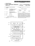
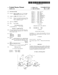
SKF Global Communication Pulp & Paper Support Segment Centre | Volume 3 | No. 9 | August 2013 SKF Pulp & Paper Practices Simple components? When you consider a complete machine or industrial process, a bearing can seem like a simple component. SKF knows, of course, they are not which is why we employ so many engineers worldwide. Simple components – and not just bearings – are often given too little attention by the people who use them. By this, I mean too little attention to their selection, installation and maintenance. To be fair, many of our customers know that bearings are the very sensitive hearts of their rotating equipment. Such customers care about all aspects of their use and are happy to ask SKF for advice and support. However, it’s the customers who do not think and act like this that I am more worried about. As I said at the start, the SKF Group employs lots of engineers. Personally, I tend to recruit design engineers because the applica tions for our simple components require a very wide range of mechanical design skills and because my engineers are involved in much more than simple life calculations. My engineers are there to work with your technical staff and the reliability of your machinery, but to do this we need to know the conditions under which your bearings operate. This issue of SKF Pulp & Paper Practices will, I hope, help you better understand what you can do to help us support you. Regards, Domenico Restaino* Manager, Application Engineering, SKF France [email protected] *shown on the right in the photograph above Calculated Rating life vs Service life Misunderstandings between bearing manufacturers and customers on technical matters are quite common. The customer, understandably, wants a reliable bearing so that he can avoid unplanned stops. If a bearing is going to fail, he wants to know when it will happen. In other words, he wants to know the bearing service life. Bearing manufacturers, unfortunately, are not able to state what the service life will be. They can only calculate the bearing rating life which is quite different. To further complicate matters, the calculated bearing rating life does not consider all the parameters that can influence service life and there are several rating life calculation methods which can give very different results. without the necessary information on operating conditions and history to deduce the most probable cause of failure. This issue of SKF Pulp and Paper Practices will examine why it isn’t possible, either today or in the near future, to state either the remaining life or the service life of a specific bearing. It will also list the information necessary for a proper bearing study and a Root Cause Failure Analysis (RCFA). Some customers see a bearing as just a piece of metal with two rings and some rolling elements. When it fails, it must be the quality or the load capacity that is the problem. Such customers don’t appre ciate that a bearing is not a simple component. I cannot count the number of customers that have asked me for service life and lubrication advice without giving me enough infor mation to check the bearing choice and whether the environment, bearing assembly and machine design will have a negative effect on life (see the example in figure 1). I have also lost count of the num ber of times that I have received either a failed bearing or a photo graph of one, sometimes too badly damaged to analyse (see figure 2), Fig. 2 A bearing that is too badly damaged to diagnose the probable failure cause. The part in the middle is what remains of the shaft that supported the bearing. Fig. 1 A drying cylinder bearing assembly. The bearings had a short service life despite the fact that the given load, oil flow and oil viscosity seemed to be correct. I didn’t immediately realise that due to the housing design, only a small proportion of the oil flow would pass through the bearing. A colleague pointed out that the oil groove in the housing bearing seat was crossed by a large groove under the bearing designed to drain the oil. Most of the oil, that should have cooled and lubricated the bearing, was draining straight out of the housing. 2 1. Why it isn’t possible to calculate a service life After reading this section of the newsletter, some of you will think that I have not given this matter the space it deserves. While it is true that I omit many things, I know that if I don’t it will become boring for many readers. Especially those who are not mechanical engineers or who, like me, close books as soon as they see that every second page is full of mathematical formulas. What we call a service life is the actual number of revolutions or the time that a bearing operates in a machine. If a Yankee bearing is dismounted and scrapped as part of preventive maintenance after ten years, then the service life is ten years even if the bearing was still in good condition. If a plain press roll bearing, damaged during transport, is mounted on the machine and then removed after three hours due to excessive vibration, then the service life is three hours. If a drying cylinder bearing is dismounted following vibration caused by spalling on the raceway after 40 years, the service life is 40 years. If we were to take a number of bearings of the same designation, manufactured at the same time, and run them with the same load and lubricant we would get the same results that they did in the lamp bulb endurance test. That is to say, they would not all have the same life. In our test, end of life is when a small spall is detected (see figure 3). Such spalls are created by alternating stresses in the structure of the steel due to the passage of the rolling elements. Under normal conditions, with no contamination and an adequate lubricant film thickness, the maximum stress is just below the surface. Due to the alternating stresses, the steel structure changes and micro cracks are created near the weak points. Figure 4, which was also shown in issue five of SKF Pulp & Paper Practices, shows the structural change between 30 and 400 microns under the raceway surface. Note the micro crack at 130 microns depth. Fig. 4 Structural change and a micro crack under the raceway surface due to alternating stresses created by over rolling. Figure 5 shows an example of an endurance test with ten bear ings. Note that the first bearing to experience flaking lived for eight million revolutions (i.e. 133 hours if the speed was 1 000 rpm), the ninth bearing managed 157.2 million revolutions (2 626 hours at 1 000 rpm) and the tenth bearing had not reached the end of its life by the time that the test was suspended. From this we can first conclude that: 1 Bearings operating in the same conditions will not achieve the same life. 2 It isn’t possible to predict the life of one specific bearing before the test. Fig. 3 A small spall (flaking) indicating the end of the bearing life Fig. 5 Example of an endurance test. Bearing number 10 9 8,0 8 24,3 26,2 7 33,9 6 62,2 5 66,0 4 104,5 133,1 3 157,2 2 Suspended 1 Bearing life Number 106 rev. 1 2 3 4 5 6 7 8 9 10 20 40 60 80 100 120 140 160 Life [× 106 revolutions] 3 All endurance tests show that if bearing lives are plotted on a graph with revolutions (or hours) on one axis and achieved life on the other, a curve can be drawn (see figure 6). This curve, showing survival probability, can be made into a model using mathematical formulas. This means that for a population of the same bearings running under exactly the same conditions, it is possible to predict the prob ability of survival. This will help an engineer choose the right bearing for an application. 70 years ago it was decided that a 0.9 probability of survival should be used. In other words that when calculating life, 90% of bearings should attain or exceed the desired life. So, when a paper machine manufacturer asks me to select a bearing for a plain press roll with a life equal or higher than 100 000 hours, it doesn’t mean that I will propose a bearing that will exceed this. It means that I will propose a bearing, based on the theoretical operating conditions supplied by the customer, that should – in theory – run for 100 000 hours or more in 90% of cases. The obvious corollary is that in 10% of cases bearings will not achieve the requested life. Imagine a board machine with 100 drying cylinder front side bearings operating in exactly the same conditions. In reality, I know that the operating conditions are not exactly the same as the speed varies between dryer groups and steam temperature changes etc., but for the purposes of this example, let’s imagine that they are. If the calculated life for 90% reliability is 200 000 hours then, in theory: • 99% of the bearings will attain or exceed 50 000 hours • 95% of them will attain or exceed 128 000 hours • 50% will attain or exceed 1.000.000 hours (five times 200 000 hours) That calculated life, in hours, is the basic rating life L10h (L for life, 10 for the 10% probability of failure with 90% reliability). This consid ers bearing load and speed only. There is the modified rating life, L10mh, which considers solid contamination, the oil viscosity ratio and the fatigue load limit as well. Note that the fatigue load limit is the load under which, assuming appropriate cleanliness levels and lubri cation regimes, bearing life is unlimited. Unfortunately, L10h and L10mh are “General Catalogue” methods that assume simple load distribution. There are other rating life methods that can take shaft, bearing and housing deformation, internal clearance and real load distribution in the bearing into account. However, for exactly the same operating conditions, the results of the calculated lives can vary a lot. I will give an example later on in the ‘Information needed for a bearing study’ section. So, when a customer asks me to calculate the life of a bearing, he’s thinking service life. I, however, can only calculate and share the rating life with him. This is when the misunderstandings begin. Especially when I am not able to guarantee that a bearing, however well mounted and maintained, will attain or exceed the calculated rating life. The probability of survival curve can be shown in another way that is much more interesting for customers i.e. as the number of bearings that reach life end per interval of time (see figure 7 for an example of what such a curve looks like). It shows that the rating life estimates the time before most bearings will have to be replaced. Bear in mind that calculated rating life is the way to select a bear ing of a certain size for an application rather than to predict the ser vice life on an individual bearing. Also that rating life is calculated based on operating conditions that may not actually be the real ones. Service life, in reality, depends on many factors that are beyond the control of the bearing manufacturer. The mounting of the bearings in a dusty environment with a large hammer, for example. A typical error is to choose the bearing with the longest rating life hoping to get the best reliability. A customer that I know did just this. He wanted to increase the reliability of a strategic fan, so he modi fied the fan so that he could mount a spherical roller bearing with a very high load capacity. A consultant calculated the L10h life as great er than several hundred million hours. The resulting service life was actually less than a week. In fact, the bearing was running with too low a load for its capacity and its rollers were sliding rather than roll ing in the loaded zone. For the sake of a quick repair without further modifications, I decided to mount the same bearing but with twothirds of the rollers removed. The fan then worked for eight years without a bearing change. Fig. 6 Survival probability curve. Bearing life Number 106 rev. 1 2 3 4 5 6 7 8 9 10 4 S [Probability of survival] 0 0,1 0,2 0,3 0,4 0,5 0,6 0,7 0,8 0,9 1,0 20 40 60 80 100 120 140 160 Life [× 106 revolutions] Bearing number 10 9 8,0 8 24,3 26,2 7 33,9 6 62,2 5 66,0 4 104,5 133,1 3 157,2 2 Suspended 1 2. The information needed for a bearing study 2.2 Drawings A bearing study is the work needed to choose the type and size of bearing based on the requested rating life, the fits and the lubrica tion. It can also include recommendations for mounting and dismounting. Such studies can be simple ones, based on the SKF General Cata logue, completed in less than ten minutes by experienced application engineers. They can also be much more complicated involving advanced computer programs and, sometimes, tests. Either way, the information needed to complete a study is the same. In the following sections, I will list and comment on the informa tion needed. In some applications, not all of it is needed, but I think it is good practice to supply it anyway. 2.1 The quantity of bearings A technical drawing with the dimensions and tolerances of the bear ing assembly or the position of the bearings is highly desirable. If this is not possible, a simple handmade sketch can help. Don’t forget to include the drive since this can have an influence. With a technical drawing or sketch, the application engineer might see something that is not considered important by the customer. Remember figure 1! I often receive cropped bearing assembly drawings. Sometimes, this means that important things that influence bearing service life are not visible for the application engineer, which may result in failures. Given this, it’s best to send complete drawings. Drawings help us understand how heat, caused by friction in the bearing or from other sources, dissipates. They also allow us to estimate bearing operating temperatures. Materials should be indicated on the drawing as thermal expan sion differences can be important. Finally, I recommend that the drawing has orthonormal vectors. Information on the number of bearings needed or the bearing con sumption per year is important for cases where high volume stand ard bearings might not be suitable for the application. This will have a direct impact on the cost involved. Fig. 7 The number of bearings reaching their life end versus time. Failure rate L10mh Failures “n” Time [log scale] Interval “t” 5 2.3 Load intensity, position and direction 2.4 Shocks Loads, including moments, should be indicated on drawings. Sup plying only bearing axial and radial load may result in low bearing service life. By way of example, let’s look at an ISO rating life calcula tion (see figure 8). It is simple to calculate the radial load on this cylindrical roller bearing and to supply only the calculated radial load: A shock load is a load, often quite high, that has a very short dura tion. It needs to be compared to the static capacity of the bearing and should be expressed in Newtons. This isn’t that easy since the shock load depends on the deceleration of the mass in movement (F = m g) and, therefore, deformations in the mechanism. Some designers choose to use oversized bearings or add more bearings. An example is vertical pulpers which experience shock loads that are difficult to estimate when recycled paper hits their rotors. Some manufactures prefer to use a spherical roller thrust bearing to accommodate the axial loads if they aren’t using over sized spherical roller bearings based on known loads. Shocks can also make rolling elements hammer the bearing cage. Consequently, the presence of repetitive shock loads will influence cage selection. Fr = (A+B).F/A F is the load acting on the shaft i.e. the red arrow If only Fr is known and no drawing with the real load position shown has been supplied, an application engineer will not see that the bearing has to withstand misalignment. The resulting calculated rating life – L10h or L10mh – could be very high. In contrast, with a drawing and knowing the load and shaft geometry, the engineer will understand that the shaft will bend under load resulting in high misalignment on the bearing. He can then use advanced software to discover that the rating life, based on the real load distribution in the bearing, is actually very low. In addition, he will understand that there is a high risk of fretting corrosion between the shaft and the bearing bore. The information supplied should be sufficient so that load direc tion variations can be well understood. A common error is to only give the maximum load thinking that if a bearing can withstand this, it can also tolerate lower loads. This is not necessarily the case as under certain conditions the rolling ele ments might slide rather than roll. As such, the contact load needs to be high enough to force them to roll. Therefore, the maximum and minimum loads should always be given. Giving only maximum load might also lead to the use of oversized bearings or a situation where no bearing can be found that will fit the requested dimensions. Take reel spool bearings, for instance. With maximum load and speed, the majority of reel spool bearings used would have a short life of a few thousand hours or less. Most automotive gearbox bearings would also have bearings with calcu lated lives of just a few dozen hours. To avoid this, it is best to supply a load histogram showing estimated loading variation and duration. Fig. 8 A drawing with load position marked. 2.5 Vibrations Vibration will have an influence on bearings. This is especially true during standstill when there is a risk of false brinelling i.e. rolling elements vibrating in the same position thereby creating fretting corrosion and wear. Vibration can also affect the lubricant. Grease can lose its consistency and move away from the bearing it’s sup posed to lubricate, for instance. As such, it’s important to supply information on acceleration, amplitude and frequency (which are all linked to each other). 2.6 Accelerations It’s not just acceleration in terms of rotational speed than can make rolling elements slide rather than roll that needs to be considered. Centrifugal acceleration, where the centre of the bearing revolves around another component’s axis such as in vibrating screens or planetary gearboxes, can also be important as it will influence bear ing cage selection. 2.7 Speeds Speeds and loads are key parameters, so a speed histogram is very useful information to have. Knowing only maximum speed can lead to lubrication issues. This is because a lubricant selected based on the maximum speed only may not build up an adequate oil film at lower speeds or run at too low temperature at minimum speed, so the grease may not bleed enough oil to correctly lubricate the bearing. Long standstill periods should also be indicated as bearings can have false brinelling damage from vibration from other machines or standstill corrosion marks, for instance. 2.8 Requested rating life A 6 B Requesting too high a rating life can lead to costly bearing assem blies, seal designs and lubricating systems being selected. In addi tion, it’s worth remembering that oversized bearings are more dif ficult to lubricate, have higher friction and will be more sensitive to low load. Pulp and paper industry applications generally have a requested rating life between 30 000 and 200 000 hours. However, in my experience once L10h is over 100 000 hours, the bearings start to be oversized and fail for reasons other than normal fatigue. 2.9 Available dimensions Supplying available dimensions at the start of a study will allow a suitable bearing to be selected. That is a bearing that fits the available space and that can be mounting on the existing shaft. 2.10 Requested running accuracy Please note that bearings with standard running accuracy are suit able for most applications. A few require increased running accuracy due to the speed or because a roll/cylinder or shaft needs to run very precisely. Overestimating the need for increased running accuracy can be expensive. I remember a tissue mill in the 1990s requesting three micron running accuracy for an embossing calender in their con verting plant. To meet this requirement I proposed preloaded spher ical roller bearings, originally designed for printing machines, with a circulating oil system. The bearing seat on the shaft was a direct taper seat made with very tight tolerances and there was a special procedure to adjust the bearing preload. A few years later, a stand ard SKF spherical roller bearing was mounted following an unplanned failure and was found to have acceptable running accu racy. As the standard bearing wasn’t preloaded, the friction was low er so grease lubrication could be used. Today the embossing calen dar runs on standard SKF spherical roller bearings mounted on SKF withdrawal sleeves and is lubricated with multi-purpose grease. 2.11 Requested rigidity or maximum deformation The different parts of a machine deform under load, so a maximum deformation might well be requested. For example, the shaft of a pinion in a bevel gear will bend under high torque deforming the support bearing and adjacent components and changing the position of the contact between the gear teeth. In such circumstances, the displacement of the pinion should be minimized in order to keep the gear mesh in the optimum range so that friction and temperature is reduced and gear life increased. A way of increasing the stiffness is to preload the bearings. If we were to do this for our bevel gear example, a preload would be selected that balanced the need for gear mesh running accuracy and the operating temperature due to increased friction in the bearing due to the preload. Note that a small bearing preload theoretically will increase bear ing life in most cases, but be aware that the inherent increased fric tion can get out of control. Before applying preload to bearings it’s best to talk to an SKF application engineer. 2.12 Requested maximum friction moment Some applications may have special needs related to the rotational friction moment. Spreader rolls, for example. This has an impact on bearing choice, but also on lubricant and seal design selection. In the pulp and paper industry, this is mainly a concern for rolls that are driven by the paper web or felt. 2.13 Preferred lubrication method and lubricant Sometimes a certain lubrication method or even a specific lubricant may be desirable. ISO VG 150 oil for a press roll in the wet section with an existing circulating oil system using that lubricant, for exam ple. Or grease for a fan due to cost reasons. With information about the preferred lubrication method and/or lubricant, an SKF application engineer is able to evaluate whether the operating conditions and bearings are compatible. 2.14 Temperatures By temperatures, I mean ambient temperatures and operating tem peratures than can affect the bearings e.g. air temperature in Yankee hood fans, steam temperatures in drying cylinders etc. It’s very important to provide realistic maximum and minimum temperatures. Please do not only give maximum temperatures for dryer section applications as it can lead to problems. For example, felt roll bearings being lubricated with high temperature grease which is suitable for the maximum temperature specified, but which may not be adequate for the lower rolls where the environment is cooler. It’s also important not to overestimate the steam temperature for drying cylinders, especially ones without journal insulation, as it can lead to recommending higher oil flow rates than necessary and the risk of leakage on some machines. There is also the risk that more expensive bearings with case hardened inner rings are proposed rather than standard bearings. 2.15 Possible contamination Information about possible contamination from the environment or from the machine should be given as this will influence bearing, seal and lubrication selection. Remember that contamination can occur during mounting (see issue 8 of SKF Pulp & Paper Practices for more information). 2.16 Mounting and dismounting requirements In some cases, the space available to mount and dismount bearings can be limited. As such, it is good to know of any restrictions that could influence bearing assembly design and mounting/dismounting procedures. The inner machine side bearing on an intermediate gear can be difficult to dismount, for example. Imagine a situation whether there is only 150 mm (5.9 inch) between gear casing and drying cylinder. The bearing assembly design and mounting/dismounting procedure needs to take account of this. Another example is replacing the bearing and adapter sleeve on a fan shaft that cannot be lifted much. If a split plummer block housing is used, it has to be mounted with the bearing, adapter sleeve and locking nut and pushed into place along the shaft. It is then not possible to use the SKF Drive-up Method since you cannot use a hydraulic nut to drive up the bearing. 7 3. Information needed for a root cause failure analysis I often get phone calls like this: “Our fan bearing is overheating! We are spraying water on the housing to cool it down, but we still have to replace the bearings three times a month! What do you recommend?” My answer is “it depends” followed by at least ten questions about operating conditions, bearing type and size, how it is mounted, what lubricant is used and so on. Most of the time this is met with silence as the caller cannot answer my questions. He didn’t mount the bearings or install the fan. The grease has been used successfully in other applications for years and he has no idea about the loads on the bearings. He called SKF because the fan’s user manual lists spare part bearings with SKF designations, so he thought we would know the operating conditions and how to fix his problem. Most often this is not the case as manufacturers have good design engi neers who know their products and don’t call SKF to validate their bearing choices except in some tricky cases. In such circumstances, I can recommend not spraying the hous ings with water since overheating bearings often have reduced internal clearance due to the inner ring being much hotter. If the housing and therefore the outer ring are cooled, it can lead to a bearing operating with no clearance and, with preload, overheating can quickly get out of control. I can also give some other recommen dations like checking that excess grease can escape and recommend that SKF supervise the next bearing mounting. However, the caller usually ends up disappointed that I could not give him an immediate solution to his problem. Doing a root cause failure analysis is a lot like a murder investiga tion. It helps if there is a body to do an autopsy on and it’s easier if it isn’t too badly damaged. Information about the body’s life can give clues, but sometimes the killer will remain unknown and the affair will join the cold cases in the archives. For meaningful root cause failure analysis, as much information about the operating conditions as possible should be supplied (see section 2). Additional useful information includes: exact bearing Fig. 9 Out of focus picture with flash reflections. 8 designation and markings, bearing operating temperatures (N.B. this is not the same as the temperature measured on the outside of the bearing housing), the service life of the previous bearing, mounting reports, brand and designation of lubricant, how the lubricant is supplied, bearing and lubricant storage time and machine modifications. When a bearing is dismounted for root cause failure analysis, as much care as possible should be taken to avoid damaging it further as this can make it more difficult to ascertain the true cause of the Fig. 10 Photograph taken with a compact camera set at 80 ISO. Fig. 11 Picture taken with the same compact camera set at 1600 ISO. Be aware that in full auto mode the camera will use a high ISO to avoid low shutter speed and that there is a risk of blurred images if there is insufficient light. problem. A sample of the lubricant from inside the dismounted bearing should be taken and then the bearing should be cleaned. Protecting it with preservative will help avoid corrosion or additional corrosion. I’m fully aware that most customers will not have all the informa tion listed above and that sometimes it’s not even possible to supply the bearing designation. That said, the more information that can be supplied, the more likely the chance of a successful failure analysis. Having the damaged bearing to examine is often central to an analysis. If it’s not possible to send the bearing to SKF, good quality photographs can help ascertain the cause of the problem. If photo graphs are sent, they should include ones showing all elements of the bearing from all sides and not just the damaged parts. Unfortunately, we often received photographs that are not very useful because they are out of focus and/or show flash reflections (see figure 9). This is a pity as you don’t need an expensive camera to supply good photographs. Many small compact digital cameras and even some smart phone cameras are good enough. Here are some tips for taking good bearing damage photographs: 1 Do not put your camera in full auto mode and don’t use flash. Instead, use manual mode to control exposure and sensor sensi tivity (ISO values). 2 Use macro mode if your camera has it. 3 Set your camera to its native ISO. This is often the smallest ISO number. High ISO will create noise that hides details (see figures 10 and 11) 4 Use a tripod and your camera’s self-timer (see figure 12) in an area where there are several light sources so that shadows are avoided. 5 As cameras may not focus correctly on a steel surface due to lack of contrast, place a ruler next to the damage and focus on that (see figure 13) 6 After taking a photograph always look at it and zoom in to check that it is in focus. Fig. 13 If there is not enough contrast for your camera to focus properly, use a ruler and focus on the edge that instead. There are other things that you can do like taking RAW instead of jpeg pictures and cropping images instead of using compression to reduce file size, but this is in danger of turning into a taking pictures tutorial. Simply following the six tips above should be good enough to start with. As always, available space restricts me. I could write a lot more and spread it over two issues of SKF Pulp & Paper Practices, but I think that might be too much. I just hope that after reading this issue you understand calculated rating life, why SKF cannot predict the service life of an individual bearing and what information you should try to collect and supply the next time you want us to do a bearing study or root cause failure analysis for you. Fig. 12 A compact camera on a tripod is usually good enough to take reasonable photographs of damaged bearings. Regards, Philippe Gachet Senior technical consultant [email protected] 9 The Power of Knowledge Engineering Seals Bearings and units Mechatronics Lubrication systems Services Drawing on five areas of competence and application-specific expertise amassed over more than 100 years, SKF brings innovative solutions to OEMs and production facilities in every major industry worldwide. These five competence areas include bearings and units, seals, lubrication systems, mechatronics (combining mechanics and electronics into intelligent systems), and a wide range of services, from 3-D computer modelling to advanced condition monitoring and reliability and asset management systems. A global presence provides SKF customers uniform quality standards and worldwide product availability. ®SKF is a registered trademarks of the SKF Group. SKF Global Pulp & Paper Segment Contact/Responsible editor [email protected] ©SKF Group 2013 The contents of this publication are the copyright of the publisher and may not be reproduced (even extracts) unless prior written permission is granted. Every care has been taken to ensure the accuracy of the information contained in this publication but no liability can be accepted for any loss or damage whether direct, indirect or consequential arising out of the use of the information contained herein. PUB 72/S9 11147/8 EN · August 2013 skf.com