1
User Manual
Cable TV RF Measurements
Software for Windows
070-9611-03
This document applies to software version 1.0 and
above.
Copyright © Tektronix, Inc. All rights reserved. Licensed software products are owned by Tektronix or its suppliers and
are protected by United States copyright laws and international treaty provisions.
Use, duplication, or disclosure by the Government is subject to restrictions as set forth in subparagraph (c)(1)(ii) of the
Rights in Technical Data and Computer Software clause at DFARS 252.227-7013, or subparagraphs (c)(1) and (2) of the
Commercial Computer Software – Restricted Rights clause at FAR 52.227-19, as applicable.
Tektronix products are covered by U.S. and foreign patents, issued and pending. Information in this publication supercedes
that in all previously published material. Specifications and price change privileges reserved.
Printed in the U.S.A.
Tektronix, Inc., P.O. Box 1000, Wilsonville, OR 97070–1000
TEKTRONIX and TEK are registered trademarks of Tektronix, Inc.
WARRANTY
Tektronix warrants that this software product will conform to the specifications in the documentation provided with the
product, when used properly in the specified operating environment, for a period of three (3) months. The warranty period
begins on the date of shipment, except that if the program is installed by Tektronix, the warranty period begins on the date
of installation or one month after the date of shipment, whichever is earlier. If this software product does not conform as
warranted, Tektronix will provide remedial services as described in the documentation provided with the product.
Tektronix does not warrant that the functions contained in this software product will meet Customer’s requirements or that
operation of the programs will be uninterrupted or error-free or that all errors will be corrected.
In order to obtain service under this warranty, Customer must notify Tektronix of the defect before the expiration of the
warranty period and make suitable arrangements for such service in accordance with the instructions received from
Tektronix. If Tektronix is unable, within a reasonable time after receipt of such notice, to provide remedial services,
Customer may terminate the license for this software product and return this software product and any associated materials
to Tektronix for credit or refund.
This warranty shall not apply to any software product that has been modified or altered by Customer. Tektronix shall not be
obligated to furnish service under this warranty with respect to any software product a) that is used in an operating
environment other than that specified or in a manner inconsistent with the User’s Manual and documentation or b) when
the software product has been integrated with other software if the result of such integration increases the time or difficulty
of analyzing or servicing the software product or the problems ascribed to the software product.
THIS WARRANTY IS GIVEN BY TEKTRONIX IN LIEU OF ANY OTHER WARRANTIES, EXPRESS OR
IMPLIED. TEKTRONIX AND ITS VENDORS DISCLAIM ANY IMPLIED WARRANTIES OF
MERCHANTABILITY OR FITNESS FOR A PARTICULAR PURPOSE. TEKTRONIX’ RESPONSIBILITY TO
PROVIDE REMEDIAL SERVICE WHEN SPECIFIED, REPLACE DEFECTIVE MEDIA, OR REFUND
CUSTOMER’S PAYMENT IS THE SOLE AND EXCLUSIVE REMEDY PROVIDED TO CUSTOMER FOR
BREACH OF THIS WARRANTY. TEKTRONIX AND ITS VENDORS WILL NOT BE LIABLE FOR ANY
INDIRECT, SPECIAL, INCIDENTAL, OR CONSEQUENTIAL DAMAGES IRRESPECTIVE OF WHETHER
TEKTRONIX OR THE VENDOR HAS ADVANCE NOTICE OF THE POSSIBILITY OF SUCH DAMAGES.
Table of Contents
Preface . . . . . . . . . . . . . . . . . . . . . . . . . . . . . . . . . . . . . . . . . . . . . . . . . . .
xiii
Welcome to Cable TV RF Measurements Software for Windows . . . . . . . . . . .
Customer Support . . . . . . . . . . . . . . . . . . . . . . . . . . . . . . . . . . . . . . . . . . . . . . . . .
What is in this Manual . . . . . . . . . . . . . . . . . . . . . . . . . . . . . . . . . . . . . . . . . . . . .
xiii
xiii
xiii
Installation . . . . . . . . . . . . . . . . . . . . . . . . . . . . . . . . . . . . . . . . . . . . . . . .
1–1
Hardware Requirements . . . . . . . . . . . . . . . . . . . . . . . . . . . . . . . . . . . . . . . . . . . .
Software Installation . . . . . . . . . . . . . . . . . . . . . . . . . . . . . . . . . . . . . . . . . . . . . .
Step-by-Step Procedure to Install the Cable TV RF Measurements Software for
Windows . . . . . . . . . . . . . . . . . . . . . . . . . . . . . . . . . . . . . . . . . . . . . . . . . . . .
Results of the Software Installation . . . . . . . . . . . . . . . . . . . . . . . . . . . . . . . . . . .
Test Equipment . . . . . . . . . . . . . . . . . . . . . . . . . . . . . . . . . . . . . . . . . . . . . . . . . . .
To Install the Equipment . . . . . . . . . . . . . . . . . . . . . . . . . . . . . . . . . . . . . . . . . . .
Upgrading From the MS-DOS Based Tektronix Cable TV Software . . . . . . . . .
1–1
1–2
1–2
1–3
1–4
1–4
1–5
Basic Tutorial . . . . . . . . . . . . . . . . . . . . . . . . . . . . . . . . . . . . . . . . . . . . . .
2–1
What Can the Cable TV RF Measurements Software for Windows Do? . . . . . .
Start the Cable TV RF Measurements Software for Windows . . . . . . . . . . . . . .
Description of the Worksheet . . . . . . . . . . . . . . . . . . . . . . . . . . . . . . . . . . . . . . . .
Navigation . . . . . . . . . . . . . . . . . . . . . . . . . . . . . . . . . . . . . . . . . . . . . . . . . . . . . .
Set Up a Worksheet . . . . . . . . . . . . . . . . . . . . . . . . . . . . . . . . . . . . . . . . . . . . . . .
Make Simple Measurements . . . . . . . . . . . . . . . . . . . . . . . . . . . . . . . . . . . . . . . .
Define and Use a Measurement Sequence . . . . . . . . . . . . . . . . . . . . . . . . . . . . . .
Display the Picture (Optional) . . . . . . . . . . . . . . . . . . . . . . . . . . . . . . . . . . . . . . .
Print (Optional) . . . . . . . . . . . . . . . . . . . . . . . . . . . . . . . . . . . . . . . . . . . . . . . . . .
End of the Tutorial . . . . . . . . . . . . . . . . . . . . . . . . . . . . . . . . . . . . . . . . . . . . . . . .
2–2
2–2
2–3
2–5
2–14
2–18
2–25
2–34
2–34
2–36
Advanced Setups Tutorial . . . . . . . . . . . . . . . . . . . . . . . . . . . . . . . . . . . .
2–39
Configure Connections . . . . . . . . . . . . . . . . . . . . . . . . . . . . . . . . . . . . . . . . . . . . .
Configure Measurement Setups . . . . . . . . . . . . . . . . . . . . . . . . . . . . . . . . . . . . . .
Attach a Different Channel Table . . . . . . . . . . . . . . . . . . . . . . . . . . . . . . . . . . . . .
Configuration Preferences . . . . . . . . . . . . . . . . . . . . . . . . . . . . . . . . . . . . . . . . . .
Review . . . . . . . . . . . . . . . . . . . . . . . . . . . . . . . . . . . . . . . . . . . . . . . . . . . . . . . . .
2–40
2–41
2–45
2–46
2–52
Advanced Measurements Tutorial . . . . . . . . . . . . . . . . . . . . . . . . . . . . .
2–53
Reset the Preferences and Worksheet for this Chapter . . . . . . . . . . . . . . . . . . . .
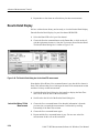
Results Detail Display . . . . . . . . . . . . . . . . . . . . . . . . . . . . . . . . . . . . . . . . . . . . .
Status Report and View Violations Displays . . . . . . . . . . . . . . . . . . . . . . . . . . . .
Copy and Export . . . . . . . . . . . . . . . . . . . . . . . . . . . . . . . . . . . . . . . . . . . . . . . . .
View Filters . . . . . . . . . . . . . . . . . . . . . . . . . . . . . . . . . . . . . . . . . . . . . . . . . . . . .
Defining Limits . . . . . . . . . . . . . . . . . . . . . . . . . . . . . . . . . . . . . . . . . . . . . . . . . .
The 2714/2715 User Defined Program (UDP) . . . . . . . . . . . . . . . . . . . . . . . . . .
Get Stored Results from the 2714/2715 . . . . . . . . . . . . . . . . . . . . . . . . . . . . . . . .
2–53
2–54
2–56
2–60
2–65
2–71
2–78
2–81
Getting Started
Operating Basics
Cable TV RF Measurements Software for Windows User Manual
i
Table of Contents
Reference
Overview . . . . . . . . . . . . . . . . . . . . . . . . . . . . . . . . . . . . . . . . . . . . . . . . . .
Parts of the Worksheet . . . . . . . . . . . . . . . . . . . . . . . . . . . . . . . . . . . . . .
3–1
3–3
Title Bar . . . . . . . . . . . . . . . . . . . . . . . . . . . . . . . . . . . . . . . . . . . . . . . . . . . . . . . .
Minimize Button . . . . . . . . . . . . . . . . . . . . . . . . . . . . . . . . . . . . . . . . . . . . . . . . .
Maximize Button . . . . . . . . . . . . . . . . . . . . . . . . . . . . . . . . . . . . . . . . . . . . . . . . .
Restore Button . . . . . . . . . . . . . . . . . . . . . . . . . . . . . . . . . . . . . . . . . . . . . . . . . . .
Worksheet Header . . . . . . . . . . . . . . . . . . . . . . . . . . . . . . . . . . . . . . . . . . . . . . . .
Channel Header . . . . . . . . . . . . . . . . . . . . . . . . . . . . . . . . . . . . . . . . . . . . . . . . . .
Measurement Header . . . . . . . . . . . . . . . . . . . . . . . . . . . . . . . . . . . . . . . . . . . . . .
Vertical Scroll Bar . . . . . . . . . . . . . . . . . . . . . . . . . . . . . . . . . . . . . . . . . . . . . . . .
Horizontal Scroll Bar . . . . . . . . . . . . . . . . . . . . . . . . . . . . . . . . . . . . . . . . . . . . . .
Cursor . . . . . . . . . . . . . . . . . . . . . . . . . . . . . . . . . . . . . . . . . . . . . . . . . . . . . . . . . .
3–3
3–4
3–4
3–4
3–4
3–5
3–6
3–6
3–6
3–7
Control-Menu Box . . . . . . . . . . . . . . . . . . . . . . . . . . . . . . . . . . . . . . . . . .
3–9
Restore . . . . . . . . . . . . . . . . . . . . . . . . . . . . . . . . . . . . . . . . . . . . . . . . . . . . . . . . .
Move . . . . . . . . . . . . . . . . . . . . . . . . . . . . . . . . . . . . . . . . . . . . . . . . . . . . . . . . . .
Size . . . . . . . . . . . . . . . . . . . . . . . . . . . . . . . . . . . . . . . . . . . . . . . . . . . . . . . . . . . .
Minimize . . . . . . . . . . . . . . . . . . . . . . . . . . . . . . . . . . . . . . . . . . . . . . . . . . . . . . .
Maximize . . . . . . . . . . . . . . . . . . . . . . . . . . . . . . . . . . . . . . . . . . . . . . . . . . . . . . .
Close . . . . . . . . . . . . . . . . . . . . . . . . . . . . . . . . . . . . . . . . . . . . . . . . . . . . . . . . . . .
Switch To . . . . . . . . . . . . . . . . . . . . . . . . . . . . . . . . . . . . . . . . . . . . . . . . . . . . . . .
3–9
3–9
3–10
3–10
3–10
3–10
3–10
Menu Bar . . . . . . . . . . . . . . . . . . . . . . . . . . . . . . . . . . . . . . . . . . . . . . . . .
3–11
File . . . . . . . . . . . . . . . . . . . . . . . . . . . . . . . . . . . . . . . . . . . . . . . . . . . . . . . . . . . .
Edit . . . . . . . . . . . . . . . . . . . . . . . . . . . . . . . . . . . . . . . . . . . . . . . . . . . . . . . . . . . .
View . . . . . . . . . . . . . . . . . . . . . . . . . . . . . . . . . . . . . . . . . . . . . . . . . . . . . . . . . . .
Measure . . . . . . . . . . . . . . . . . . . . . . . . . . . . . . . . . . . . . . . . . . . . . . . . . . . . . . . .
Configure . . . . . . . . . . . . . . . . . . . . . . . . . . . . . . . . . . . . . . . . . . . . . . . . . . . . . . .
Execute . . . . . . . . . . . . . . . . . . . . . . . . . . . . . . . . . . . . . . . . . . . . . . . . . . . . . . . . .
Help . . . . . . . . . . . . . . . . . . . . . . . . . . . . . . . . . . . . . . . . . . . . . . . . . . . . . . . . . . .
Button Bar . . . . . . . . . . . . . . . . . . . . . . . . . . . . . . . . . . . . . . . . . . . . . . . . . . . . . .
3–11
3–18
3–21
3–38
3–43
3–70
3–70
3–72
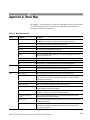
Appendix A: Menu Map . . . . . . . . . . . . . . . . . . . . . . . . . . . . . . . . . . . . .
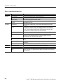
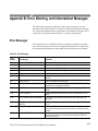
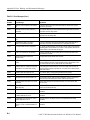
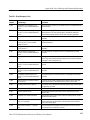
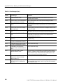
Appendix B: Error, Warning, and Informational Messages . . . . . . . .
A–1
B–1
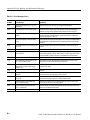
Error Messages . . . . . . . . . . . . . . . . . . . . . . . . . . . . . . . . . . . . . . . . . . . . . . . . . . .
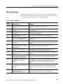
Warning Messages . . . . . . . . . . . . . . . . . . . . . . . . . . . . . . . . . . . . . . . . . . . . . . . .
Informational Messages . . . . . . . . . . . . . . . . . . . . . . . . . . . . . . . . . . . . . . . . . . . .
B–1
B–9
B–10
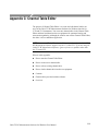
Appendix C: Channel Table Editor . . . . . . . . . . . . . . . . . . . . . . . . . . . .
C–1
How to Start the Channel Table Editor . . . . . . . . . . . . . . . . . . . . . . . . . . . . . . . .
Create a New Channel Table . . . . . . . . . . . . . . . . . . . . . . . . . . . . . . . . . . . . . . . .
Load a Channel Table into the Test Equipment . . . . . . . . . . . . . . . . . . . . . . . . . .
Cautions . . . . . . . . . . . . . . . . . . . . . . . . . . . . . . . . . . . . . . . . . . . . . . . . . . . . . . . .
Channel Tables Provided . . . . . . . . . . . . . . . . . . . . . . . . . . . . . . . . . . . . . . . . . . .
Overview . . . . . . . . . . . . . . . . . . . . . . . . . . . . . . . . . . . . . . . . . . . . . . . . . . . . . . .
Button Bar . . . . . . . . . . . . . . . . . . . . . . . . . . . . . . . . . . . . . . . . . . . . . . . . . . . . . .
Channel Table Fields . . . . . . . . . . . . . . . . . . . . . . . . . . . . . . . . . . . . . . . . . . . . . .
C–2
C–3
C–9
C–9
C–12
C–14
C–27
C–27
Appendices
ii
Cable TV RF Measurements Software for Windows User Manual
Table of Contents
Appendix D: FCC Measurements . . . . . . . . . . . . . . . . . . . . . . . . . . . . .
D–1
Organizing Worksheets and Measurement Results . . . . . . . . . . . . . . . . . . . . . . .
FCC Headend Measurements . . . . . . . . . . . . . . . . . . . . . . . . . . . . . . . . . . . . . . . .
FCC Field Measurements . . . . . . . . . . . . . . . . . . . . . . . . . . . . . . . . . . . . . . . . . . .
D–1
D–3
D–5
Appendix E: Files . . . . . . . . . . . . . . . . . . . . . . . . . . . . . . . . . . . . . . . . . .
E–1
Approximate File Sizes . . . . . . . . . . . . . . . . . . . . . . . . . . . . . . . . . . . . . . . . . . . .
Naming Conventions . . . . . . . . . . . . . . . . . . . . . . . . . . . . . . . . . . . . . . . . . . . . . .
User Aids . . . . . . . . . . . . . . . . . . . . . . . . . . . . . . . . . . . . . . . . . . . . . . . . . . . . . . .
How to Archive a Worksheet . . . . . . . . . . . . . . . . . . . . . . . . . . . . . . . . . . . . . . . .
The WIN.INI File . . . . . . . . . . . . . . . . . . . . . . . . . . . . . . . . . . . . . . . . . . . . . . . . .
The 271X_SW.INI File . . . . . . . . . . . . . . . . . . . . . . . . . . . . . . . . . . . . . . . . . . . .
E–1
E–2
E–2
E–4
E–5
E–5
Appendix F: Controlling a 2714/2715 Over a Modem . . . . . . . . . . . . .
F–1
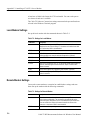
Terminal Program Settings . . . . . . . . . . . . . . . . . . . . . . . . . . . . . . . . . . . . . . . . . .
Local Modem Settings . . . . . . . . . . . . . . . . . . . . . . . . . . . . . . . . . . . . . . . . . . . . .
Remote Modem Settings . . . . . . . . . . . . . . . . . . . . . . . . . . . . . . . . . . . . . . . . . . .
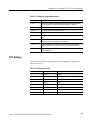
271X Settings . . . . . . . . . . . . . . . . . . . . . . . . . . . . . . . . . . . . . . . . . . . . . . . . . . . .
F–1
F–2
F–2
F–3
Glossary
Index
Cable TV RF Measurements Software for Windows User Manual
iii
Table of Contents
iv
Cable TV RF Measurements Software for Windows User Manual
Table of Contents
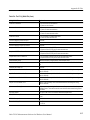
List of Figures
Figure 2–1: The default worksheet display . . . . . . . . . . . . . . . . . . . . . .
Figure 2–2: The Worksheet Header . . . . . . . . . . . . . . . . . . . . . . . . . . . .
Figure 2–3: The drop-down File menu . . . . . . . . . . . . . . . . . . . . . . . . .
Figure 2–4: The Open dialog box . . . . . . . . . . . . . . . . . . . . . . . . . . . . . .
Figure 2–5: The Test ID dialog box . . . . . . . . . . . . . . . . . . . . . . . . . . . .
Figure 2–6: The spreadsheet scrolled to the Cross
Modulation column . . . . . . . . . . . . . . . . . . . . . . . . . . . . . . . . . . . . . .
Figure 2–7: Example of a cell selected on the spreadsheet . . . . . . . . .
Figure 2–8: A group of cells selected . . . . . . . . . . . . . . . . . . . . . . . . . . .
Figure 2–9: Warning dialog box . . . . . . . . . . . . . . . . . . . . . . . . . . . . . . .
Figure 2–10: The New dialog box . . . . . . . . . . . . . . . . . . . . . . . . . . . . . .
Figure 2–11: The Save As dialog box . . . . . . . . . . . . . . . . . . . . . . . . . . .
Figure 2–12: The Test ID dialog box . . . . . . . . . . . . . . . . . . . . . . . . . . .
Figure 2–13: The worksheet header after filling in all information . .
Figure 2–14: Measurement Execution Dialog box . . . . . . . . . . . . . . . .
Figure 2–15: Message dialog box . . . . . . . . . . . . . . . . . . . . . . . . . . . . . .
Figure 2–16: Measurement Dialog box . . . . . . . . . . . . . . . . . . . . . . . . .
Figure 2–17: The spreadsheet after making a few measurements . . .
Figure 2–18: Measurement Execution dialog box . . . . . . . . . . . . . . . .
Figure 2–19: The spreadsheet cells after making a group
of measurements . . . . . . . . . . . . . . . . . . . . . . . . . . . . . . . . . . . . . . . .
Figure 2–20: The Results Detail dialog box . . . . . . . . . . . . . . . . . . . . .
Figure 2–21: The Global View of the spreadsheet . . . . . . . . . . . . . . . .
Figure 2–22: The Measurement Sequence dialog box (U.S.A. only) . .
Figure 2–23: The Measurement Sequence dialog box (non–U.S.A.) .
Figure 2–24: The Measurement Sequence dialog box,
measurements selected . . . . . . . . . . . . . . . . . . . . . . . . . . . . . . . . . . .
Figure 2–25: The Edit Time Parameters dialog box . . . . . . . . . . . . . .
Figure 2–26: The Sequence Measurement Execution dialog box . . . .
Figure 2–27: View Filter Warning dialog box . . . . . . . . . . . . . . . . . . . .
Figure 2–28: Measurement Sequence results with view filter on . . . .
Figure 2–29: The FCC Pre-Converter Measurements dialog box . . .
Figure 2–30: Measurement Sequence dialog box after Auto Selection
command and a few additional measurements . . . . . . . . . . . . . . .
Figure 2–31: The Print Setup dialog box . . . . . . . . . . . . . . . . . . . . . . .
Figure 2–32: The Print dialog box . . . . . . . . . . . . . . . . . . . . . . . . . . . . .
Cable TV RF Measurements Software for Windows User Manual
2–3
2–4
2–6
2–6
2–8
2–10
2–11
2–13
2–14
2–15
2–16
2–17
2–17
2–19
2–19
2–20
2–20
2–21
2–22
2–23
2–24
2–26
2–27
2–28
2–28
2–29
2–30
2–30
2–32
2–33
2–35
2–35
v
Table of Contents
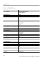
Figure 2–33: The Connections dialog box . . . . . . . . . . . . . . . . . . . . . . .
Figure 2–34: The Measurement Setups dialog box . . . . . . . . . . . . . . .
Figure 2–35: The Edit Setups dialog box for channel 2 . . . . . . . . . . . .
Figure 2–36: The Get Defaults dialog box . . . . . . . . . . . . . . . . . . . . . . .
Figure 2–37: The Worksheet Info dialog box used to change the
Channel Table . . . . . . . . . . . . . . . . . . . . . . . . . . . . . . . . . . . . . . . . . .
Figure 2–38: Warning message that the worksheet has changed . . . .
Figure 2–39: The Preferences dialog box . . . . . . . . . . . . . . . . . . . . . . .
Figure 2–40: A three-dimensional view of a spreadsheet . . . . . . . . . . .
Figure 2–41: The life of a cell with Collect History turned on and off
Figure 2–42: Prompt to connect the input signal to the 271X . . . . . . .
Figure 2–43: Message box stating that measurements are paused . . .
Figure 2–44: The measurement Alarm message box . . . . . . . . . . . . . .
Figure 2–45: Message box stating that measurements are paused . . .
Figure 2–46: The Results Detail dialog box for the Hum/LFD
measurement . . . . . . . . . . . . . . . . . . . . . . . . . . . . . . . . . . . . . . . . . . .
Figure 2–47: The Results Detail dialog box for the In-Channel
Response measurement for the first channel . . . . . . . . . . . . . . . . .
Figure 2–48: The worksheet after making all of the measurements
for the first three channels . . . . . . . . . . . . . . . . . . . . . . . . . . . . . . . .
Figure 2–49: The Status Report . . . . . . . . . . . . . . . . . . . . . . . . . . . . . . .
Figure 2–50: The View Violations display . . . . . . . . . . . . . . . . . . . . . . .
Figure 2–51: The Results Detail display . . . . . . . . . . . . . . . . . . . . . . . .
Figure 2–52: The Copy dialog box . . . . . . . . . . . . . . . . . . . . . . . . . . . . .
Figure 2–53: The results of pasting the Clipboard data into Excel . .
Figure 2–54: The Copy dialog box . . . . . . . . . . . . . . . . . . . . . . . . . . . . .
Figure 2–55: The result of the Copy As Displayed pasted into Excel .
Figure 2–56: Data for the Carrier to Noise Ratio for four channels .
Figure 2–57: The Export dialog box . . . . . . . . . . . . . . . . . . . . . . . . . . .
Figure 2–58: Measurements and Channels View Filter dialog box . .
Figure 2–59: The Measurements and Channels dialog box . . . . . . . . .
Figure 2–60: The spreadsheet with the Measurements and
Channels View Filter on . . . . . . . . . . . . . . . . . . . . . . . . . . . . . . . . . .
Figure 2–61: The message to turn on the Measurement Sequence
Results filter . . . . . . . . . . . . . . . . . . . . . . . . . . . . . . . . . . . . . . . . . . . .
Figure 2–62: The spreadsheet with the Measurement Sequence
Results filter turned on . . . . . . . . . . . . . . . . . . . . . . . . . . . . . . . . . . .
Figure 2–63: The results of turning on the Test ID Results filter . . . .
Figure 2–64: The Measurement Limits dialog box . . . . . . . . . . . . . . .
Figure 2–65: The Edit Limits File – ntsc.lim dialog box. . . . . . . . . . . .
vi
2–40
2–41
2–42
2–44
2–46
2–46
2–47
2–48
2–49
2–51
2–51
2–51
2–52
2–54
2–55
2–56
2–57
2–58
2–59
2–60
2–61
2–62
2–63
2–64
2–64
2–66
2–67
2–67
2–69
2–69
2–70
2–72
2–73
Cable TV RF Measurements Software for Windows User Manual
Table of Contents
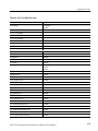
Figure 2–66: How limits work . . . . . . . . . . . . . . . . . . . . . . . . . . . . . . . .
Figure 2–67: An example of an error message . . . . . . . . . . . . . . . . . . .
Figure 2–68: The summary limits . . . . . . . . . . . . . . . . . . . . . . . . . . . . .
Figure 2–69: The Parameters dialog box . . . . . . . . . . . . . . . . . . . . . . .
Figure 2–70: Worksheet header after being edited for the UDP . . . .
Figure 2–71: The Create 2714/2715 UDP dialog box . . . . . . . . . . . . . .
Figure 2–72: The Get Stored Results dialog box . . . . . . . . . . . . . . . . .
Figure 2–73: The Export dialog box . . . . . . . . . . . . . . . . . . . . . . . . . . .
Figure 2–74: The Get Stored Results dialog box after the selected
site results have been exported to a results file. . . . . . . . . . . . . . . .
Figure 2–75: A warning that the site name does not match the
current site name in the worksheet. . . . . . . . . . . . . . . . . . . . . . . . .
Figure 2–76: Warning that the current site name does not match the
imported site name . . . . . . . . . . . . . . . . . . . . . . . . . . . . . . . . . . . . . .
Figure 2–77: Warning that the worksheet and the 271X the
Channel Tables do not match . . . . . . . . . . . . . . . . . . . . . . . . . . . . . .
Figure 2–78: The Import Results dialog box . . . . . . . . . . . . . . . . . . . .
Figure 2–79: Message box that tells you that the import procedure is
finished . . . . . . . . . . . . . . . . . . . . . . . . . . . . . . . . . . . . . . . . . . . . . . . .
2–86
Figure 3–1: Parts of the Cable TV RF Measurements Software
for Windows worksheet . . . . . . . . . . . . . . . . . . . . . . . . . . . . . . . . . .
Figure 3–2: The Worksheet Header . . . . . . . . . . . . . . . . . . . . . . . . . . . .
Figure 3–3: The Control Menu Box . . . . . . . . . . . . . . . . . . . . . . . . . . . .
Figure 3–4: The File Menu . . . . . . . . . . . . . . . . . . . . . . . . . . . . . . . . . . .
Figure 3–5: The New dialog box . . . . . . . . . . . . . . . . . . . . . . . . . . . . . . .
Figure 3–6: The Open dialog box . . . . . . . . . . . . . . . . . . . . . . . . . . . . . .
Figure 3–7: The Save As dialog box . . . . . . . . . . . . . . . . . . . . . . . . . . . .
Figure 3–8: The Import dialog box . . . . . . . . . . . . . . . . . . . . . . . . . . . .
Figure 3–9: The Export dialog box . . . . . . . . . . . . . . . . . . . . . . . . . . . .
Figure 3–10: The Print dialog box . . . . . . . . . . . . . . . . . . . . . . . . . . . . .
Figure 3–11: The Print Setup dialog box . . . . . . . . . . . . . . . . . . . . . . . .
Figure 3–12: The Edit Menu . . . . . . . . . . . . . . . . . . . . . . . . . . . . . . . . .
Figure 3–13: The Copy dialog box . . . . . . . . . . . . . . . . . . . . . . . . . . . . .
Figure 3–14: The Clear dialog box . . . . . . . . . . . . . . . . . . . . . . . . . . . . .
Figure 3–15: The View Menu . . . . . . . . . . . . . . . . . . . . . . . . . . . . . . . . .
Figure 3–16: The Status Report . . . . . . . . . . . . . . . . . . . . . . . . . . . . . . .
Figure 3–17: View Violations dialog box . . . . . . . . . . . . . . . . . . . . . . . .
Figure 3–18: Results Detail dialog box . . . . . . . . . . . . . . . . . . . . . . . . .
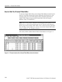
Figure 3–19: The 24 hour Carrier Summary display . . . . . . . . . . . . .
3–3
3–4
3–9
3–11
3–12
3–13
3–13
3–14
3–15
3–16
3–18
3–18
3–19
3–21
3–21
3–22
3–25
3–26
3–30
Cable TV RF Measurements Software for Windows User Manual
2–74
2–74
2–77
2–78
2–79
2–80
2–82
2–82
2–83
2–83
2–84
2–84
2–85
vii
Table of Contents
Figure 3–20: Example of a Channel Summary . . . . . . . . . . . . . . . . . . .
Figure 3–21: Example of a Measurement Summary . . . . . . . . . . . . . .
Figure 3–22: Global View dialog box . . . . . . . . . . . . . . . . . . . . . . . . . . .
Figure 3–23: The Measurements and Channels dialog box . . . . . . . . .
Figure 3–24: Worksheet, with the Measurements and Channel
View Filter on . . . . . . . . . . . . . . . . . . . . . . . . . . . . . . . . . . . . . . . . . .
Figure 3–25: Warning message . . . . . . . . . . . . . . . . . . . . . . . . . . . . . . .
Figure 3–26: The Row Header Fields dialog box . . . . . . . . . . . . . . . . .
Figure 3–27: The Measure Menu . . . . . . . . . . . . . . . . . . . . . . . . . . . . . .
Figure 3–28: The Get Stored Results dialog box . . . . . . . . . . . . . . . . .
Figure 3–29: The Import Results dialog box . . . . . . . . . . . . . . . . . . . .
Figure 3–30: Imported results messages . . . . . . . . . . . . . . . . . . . . . . . .
Figure 3–31: The Configure Menu . . . . . . . . . . . . . . . . . . . . . . . . . . . . .
Figure 3–32: The Worksheet Info dialog box . . . . . . . . . . . . . . . . . . . .
Figure 3–33: The Test ID dialog box . . . . . . . . . . . . . . . . . . . . . . . . . . .
Figure 3–34: The Preferences dialog box . . . . . . . . . . . . . . . . . . . . . . .
Figure 3–35: How measurements are saved when history is turned
off and then on . . . . . . . . . . . . . . . . . . . . . . . . . . . . . . . . . . . . . . . . . .
Figure 3–36: Measurement Sequence dialog box . . . . . . . . . . . . . . . . .
Figure 3–37: Edit Time Parameter dialog box . . . . . . . . . . . . . . . . . . .
Figure 3–38: Create 2714/2715 UDP dialog box . . . . . . . . . . . . . . . . . .
Figure 3–39: The Measurement Limits dialog box . . . . . . . . . . . . . . .
Figure 3–40: The Edit Limits File dialog box . . . . . . . . . . . . . . . . . . . .
Figure 3–41: How the upper and lower limits work . . . . . . . . . . . . . .
Figure 3–42: The Save As Defaults dialog box . . . . . . . . . . . . . . . . . . .
Figure 3–43: Summary Limits dialog box . . . . . . . . . . . . . . . . . . . . . . .
Figure 3–44: The Parameters dialog box . . . . . . . . . . . . . . . . . . . . . . .
Figure 3–45: The Measurement Setups dialog box . . . . . . . . . . . . . . .
Figure 3–46: The Edit Setups dialog box . . . . . . . . . . . . . . . . . . . . . . .
Figure 3–47: CTB/CSO measurement results distribution and
CSO setup restrictions . . . . . . . . . . . . . . . . . . . . . . . . . . . . . . . . . . .
Figure 3–48: Get Defaults dialog box . . . . . . . . . . . . . . . . . . . . . . . . . .
Figure 3–49: Save As Defaults dialog box . . . . . . . . . . . . . . . . . . . . . . .
Figure 3–50: Copy to All Channels dialog box . . . . . . . . . . . . . . . . . . .
Figure 3–51: Connections dialog box . . . . . . . . . . . . . . . . . . . . . . . . . . .
Figure 3–52: The Help Menu . . . . . . . . . . . . . . . . . . . . . . . . . . . . . . . . .
Figure 3–53: The Help Contents dialog box . . . . . . . . . . . . . . . . . . . . .
Figure 3–54: The About dialog box . . . . . . . . . . . . . . . . . . . . . . . . . . . .
viii
3–31
3–32
3–33
3–35
3–35
3–37
3–38
3–39
3–41
3–42
3–43
3–43
3–44
3–45
3–46
3–47
3–49
3–51
3–52
3–57
3–58
3–59
3–60
3–61
3–62
3–62
3–64
3–67
3–67
3–68
3–68
3–69
3–70
3–71
3–71
Cable TV RF Measurements Software for Windows User Manual
Table of Contents
Figure C–1: The main window of the Channel Table Editor
with std.cht loaded. . . . . . . . . . . . . . . . . . . . . . . . . . . . . . . . . . . . . . .
Figure C–2: The Edit Table Information dialog box . . . . . . . . . . . . . .
Figure C–3: The test1.cht Channel Table before beginning the edits .
Figure C–4: The Channel Table Editor with data for one
channel entered . . . . . . . . . . . . . . . . . . . . . . . . . . . . . . . . . . . . . . . . .
Figure C–5: Warning that you have made changes and not
saved them . . . . . . . . . . . . . . . . . . . . . . . . . . . . . . . . . . . . . . . . . . . . .
Figure C–6: The Open dialog box . . . . . . . . . . . . . . . . . . . . . . . . . . . . .
Figure C–7: The std.cht channel table (with all fields shown) . . . . . .
Figure C–8: The Save As dialog box . . . . . . . . . . . . . . . . . . . . . . . . . . .
Figure C–9: The Copy Fields to End dialog box . . . . . . . . . . . . . . . . .
Figure C–10: The To dialog box . . . . . . . . . . . . . . . . . . . . . . . . . . . . . . .
Figure C–11: The Control Box menu . . . . . . . . . . . . . . . . . . . . . . . . . . .
Figure C–12: The Menu Bar . . . . . . . . . . . . . . . . . . . . . . . . . . . . . . . . .
Figure C–13: The File menu . . . . . . . . . . . . . . . . . . . . . . . . . . . . . . . . . .
Figure C–14: The Open dialog box . . . . . . . . . . . . . . . . . . . . . . . . . . . .
Figure C–15: The Save As dialog box . . . . . . . . . . . . . . . . . . . . . . . . . .
Figure C–16: The Print dialog box . . . . . . . . . . . . . . . . . . . . . . . . . . . .
Figure C–17: The Print Setup dialog box . . . . . . . . . . . . . . . . . . . . . . .
Figure C–18: The Edit Menu . . . . . . . . . . . . . . . . . . . . . . . . . . . . . . . . .
Figure C–19: The Copy Fields to End dialog box . . . . . . . . . . . . . . . .
Figure C–20: The Edit Table Information dialog box . . . . . . . . . . . . .
Figure C–21: The View Channel Table Fields dialog box . . . . . . . . . .
Figure C–22: The Transfer Menu . . . . . . . . . . . . . . . . . . . . . . . . . . . . .
Figure C–23: The To dialog box . . . . . . . . . . . . . . . . . . . . . . . . . . . . . . .
Figure C–24: The From dialog box . . . . . . . . . . . . . . . . . . . . . . . . . . . .
Figure C–25: The From (Select Table) dialog box . . . . . . . . . . . . . . . .
Figure C–26: The Delete dialog box . . . . . . . . . . . . . . . . . . . . . . . . . . . .
Figure C–27: The Delete (Select Table) dialog box . . . . . . . . . . . . . . .
Figure C–28: The Select dialog box . . . . . . . . . . . . . . . . . . . . . . . . . . . .
Figure C–29: The Limit Check dialog box . . . . . . . . . . . . . . . . . . . . . .
Figure C–30: Warning message that multiple channel widths are
incompatible with some 2714 and 2715 instruments . . . . . . . . . . .
Figure C–31: Limit Check passed message . . . . . . . . . . . . . . . . . . . . . .
Figure C–32: The Connections dialog box . . . . . . . . . . . . . . . . . . . . . .
Figure C–33: The Channel Table Editor About dialog box . . . . . . . . .
Figure C–34: The Global View from the software application. . . . . .
C–5
C–5
C–6
C–7
C–8
C–9
C–14
C–15
C–15
C–16
C–16
C–17
C–17
C–18
C–18
C–19
C–20
C–21
C–22
C–22
C–23
C–23
C–24
C–24
C–25
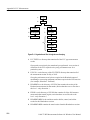
Figure D–1: Organization of files for logical record keeping . . . . . . .
D–2
Cable TV RF Measurements Software for Windows User Manual
C–2
C–3
C–4
C–4
C–25
C–25
C–26
C–27
C–30
ix
Table of Contents
x
Cable TV RF Measurements Software for Windows User Manual
Table of Contents
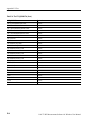
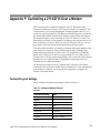
List of Tables
Table 1–1: 271X_SW directory . . . . . . . . . . . . . . . . . . . . . . . . . . . . . . .
Table 1–2: GPIB board settings . . . . . . . . . . . . . . . . . . . . . . . . . . . . . .
Table 1–3: 271X (Option 03) GPIB . . . . . . . . . . . . . . . . . . . . . . . . . . . .
Table 1–4: 271X (Option 08) RS232 . . . . . . . . . . . . . . . . . . . . . . . . . . .
1–3
1–4
1–4
1–5
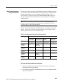
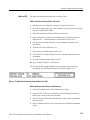
Table 2–1: Measurements Taken by Auto Selection buttons . . . . . . .
2–31
Table 3–1: Measurements under each measurement header . . . . . . .
Table 3–2: The results of copying one cell with history into Word
for Windows . . . . . . . . . . . . . . . . . . . . . . . . . . . . . . . . . . . . . . . . . . .
Table 3–3: The results of copying one cell using the As Displayed
format . . . . . . . . . . . . . . . . . . . . . . . . . . . . . . . . . . . . . . . . . . . . . . . .
Table 3–4: The Measurement Summaries in the status report . . . . .
Table 3–5: Explanation of the notes field . . . . . . . . . . . . . . . . . . . . . . .
Table 3–6: Measurements Run Using Auto Configure buttons . . . . .
Table 3–7: UDP Information loaded into the 271X . . . . . . . . . . . . . . .
Table 3–8: Measurements that require operator input . . . . . . . . . . . .
Table 3–9: Modes for Unattended UDPs . . . . . . . . . . . . . . . . . . . . . . .
3–17
3–20
3–22
3–28
3–50
3–53
3–55
3–55
Table A–1: Menu Bar menu map . . . . . . . . . . . . . . . . . . . . . . . . . . . . .
A–1
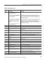
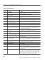
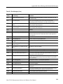
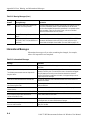
Table B–1: Error Messages . . . . . . . . . . . . . . . . . . . . . . . . . . . . . . . . . .
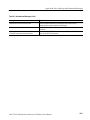
Table B–2: Warning Messages . . . . . . . . . . . . . . . . . . . . . . . . . . . . . . . .
Table B–3: Informational Messages . . . . . . . . . . . . . . . . . . . . . . . . . . .
B–1
B–9
B–10
Table C–1: Channel Table . . . . . . . . . . . . . . . . . . . . . . . . . . . . . . . . . . .
Table C–2: The Channel Table fields available from each group . . .
C–13
C–20
Table D–1: How the results are exported from the 271X . . . . . . . . . .
D–11
Table E–1: Files and their approximate sizes . . . . . . . . . . . . . . . . . . .
Table E–2: Software file types and their naming conventions . . . . . .
Table E–3: Help Topics and Their Associated Files . . . . . . . . . . . . . .
Table E–4: The 271X_SW.INI File . . . . . . . . . . . . . . . . . . . . . . . . . . . .
E–1
E–2
E–3
E–6
Table F–1: Settings for Windows Terminal Program . . . . . . . . . . . . .
Table F–2: Settings for Local Modem . . . . . . . . . . . . . . . . . . . . . . . . .
Table F–3: Settings for Remote Modem . . . . . . . . . . . . . . . . . . . . . . . .
Table F–4: Settings for the 271X . . . . . . . . . . . . . . . . . . . . . . . . . . . . . .
F–1
F–2
F–2
F–3
Cable TV RF Measurements Software for Windows User Manual
3–19
xi
Table of Contents
xii
Cable TV RF Measurements Software for Windows User Manual
Preface
Welcome to Cable TV RF Measurements Software for Windows
The Cable TV RF Measurements Software for Windows is Microsoft Windowsbased software to control and display measurement results of the 2714 and 2715.
The point and click user interface makes operation easy, even for the inexperienced user. Making a measurement is as simple as selecting a channel and
measurement type and clicking a mouse. In addition, the software can automatically monitor all in-service RF measurements1 and signal an alarm when a
measurement exceeds a specified limit.
Measurement results are displayed in a table of channel vs. measurement type.
For any measurement on a particular channel, you simply click the mouse on that
data cell, and a window appears with more information.
As with other Windows-based software, Cable TV RF Measurements Software
for Windows data is exportable to other Windows-based software, such as
Microsoft Excel, for in-depth data analysis.
Customer Support
If you have any problems using this product, please call the Tektronix help line
at:
1-800-TEKWIDE (1-800-835-9433)
What is in this Manual
This manual assumes that you are familiar with Windows 3.1 and its terms. For
more information about Windows, please refer to the Windows tutorial in the
Windows reference manual.
The basic layout of this manual is:
1. This Preface.
2. Installation instructions to load the Cable TV RF Measurements Software for
Windows application onto the hard disk and prepare it for operation.
3. A tutorial for the beginning user, including basic terminology and how to
make simple measurements.
1
The 2715 Spectrum Analyzer with either Option 50 or Option 75 installed is capable of frequencies up to 2.15 GHz.
Frequencies above 1.8 GHz are not supported by the Cable TV RF Measurements Software.
Cable TV RF Measurements Software for Windows User Manual
xiii
Preface
4. A reference that explains each function of the software and the use of more
advanced setup procedures, measurements, and displays.
5. Appendices:
xiv
H
A Menu Map to give you a quick overview of what is available to you.
H
Error, Warning, and Informational Messages.
H
An overview of the Channel Table Editor.
H
How to use the Cable TV RF Measurements Software for Windows
application to meet FCC measurement requirements for monitoring a
cable system.
H
Additional information about the Cable TV RF Measurements Software
for Windows files (how to archive worksheets, messages, and so forth.)
Cable TV RF Measurements Software for Windows User Manual
Installation
Each Cable TV RF Measurements Software for Windows Package contains the
following:
H
One 31@2 inch diskette (Tektronix part number 063-2498-XX)
H
This manual (part number 070-9611-XX)
Hardware Requirements
Minimum computer requirements for the Cable TV RF Measurements Software
for Windows to operate properly:
H
MS-DOS compatible 16 MHz 386 personal computer with hard drive
(486-33 is recommended)
H
MS-DOS 5.0
H
Microsoft Windows 3.1
NOTE. Microsoft Windows NT is NOT recommended. Use at your own risk.
H
VGA display
H
Video Display board for View Picture mode – optional
(Video Blaster recommended)
H
2 MB of RAM (8 MB recommended)
H
4 MB of free space on the hard drive
H
GPIB or RS-232 interface. The GPIB hardware is assumed to be National
Instruments GPIB-PCIIA with version 2.1.1 of the GPIB driver software.
(Tektronix provides an appropriate GPIB board and driver software in the
S3FG210 PC GPIB Package.) If using RS-232 ports, make sure that your
computer has enough Com Ports.
NOTE. If more than one GPIB board is installed, the software must use board
GPIB0.
H
Mouse or other pointing device is recommended but not required.
Cable TV RF Measurements Software for Windows User Manual
1–1
Installation
Software Installation
If you also have CSS500 installed on your computer, the Cable TV RF Measurements Software for Windows is not required. See Appendix E for some special
things to consider before installing the software.
Step-by-Step Procedure to Install the Cable TV RF Measurements Software for
Windows
1. Check the README.TXT file, on the distribution diskette, for additional
information. This is very important if you are upgrading from a previous
version.
2. Create the directory on your hard drive where you want the software
installed.
For example: to create the directory “271X_SW” on the C drive, type:
(Puts you in the C drive.)
(Puts you at the root of the C drive.)
(Creates the software directory.)
(Changes to the software directory.)
3. Copy the files from the distribution diskette to the directory created in step 2.
For example: copy the files from the B drive to C:\271X_SW.
Insert the distribution diskette into the B drive. Type:
(Copies everything from the B drive into the
current directory C:\271X_SW.)
4. Install the software.
NOTE. After running , INSTALL.BAT, you may remove the INSTALL.BAT and
SETUPCSS.EXE files to save disk space.
From the directory created in step 2, execute the INSTALL.BAT batch file.
Type:
(This batch file creates all the program files and
directories required by the software.)
5. Create the Windows Program Group and Program Items.
Enter Windows, then follow the Windows Program Manager instructions to
create a Program Group and Program Item for the software application
1–2
Cable TV RF Measurements Software for Windows User Manual
Installation
(271X_SW.EXE). Optionally, you can create a Program Item for the Channel
Table Editor (CTLOADE.EXE).
Results of the Software Installation
The following lists the icons, directories, and files created as a result of the
software installation.
Windows Program Items
Directories Created
(Cable TV RF Measurements Software for Windows)
(Channel Table Editor)
271X_SW (or whatever you chose to call it)
Sub-directories of 271X_SW:
List of Files
LIMITS Sub-Directory
HELP Sub-Directory
Table 1–1: 271X_SW directory
271X_SW.EXE
EUR_BG.CHT
MSMTSTUB.DLL
B’CAST.CHT
EUR_I.CHT
README.TXT
CATV-HRC.CHT
EUR_I1.CHT
SETUPCSS.EXE
CATV-IRC.CHT
EXPORTDB.EXE
STD.CHT
CATV-STD.CHT
HRC.CHT
STDOFST.CHT
CHINA-DK.CHT
INSTALL.BAT
STNDRD.CHT
CHIN_DK.CHT
IRC.CHT
TBPRO1W.DLL
CTLOADD.DLL
JAPAN-M.CHT
TBPRO2W.DLL
CTLOADE.EXE
JAPAN_M.CHT
TBPRO3W.DLL
EUR-BG.CHT
MSMT.DLL
TBPRO5W.DLL
EUR-I.CHT
MSMTREAL.DLL
TEKIO.DLL
All the help files are in this sub-directory. See Appendix E for how to edit these
to fit your special requirements.
Cable TV RF Measurements Software for Windows User Manual
1–3
Installation
NOTE. All Channel Table and Limits files provided with the software application
are Read Only.
Test Equipment
The following test equipment is required to complete this installation:
H
A 2714 or 2715 Cable TV Spectrum Analyzer (If either instrument can be
used, then 271X is called out. If something is instrument specific, then one
or the other is called out.)
H
If the 271X has option 08 installed, an RS-232 cable is required. The 25-pin
RS-232 cable is Tektronix part number 012-1380-00. The 9-pin RS-232
cable is Tektronix part number 012-1379-00.
To Install the Equipment
Use the following procedures to install the equipment.
GPIB Board
The software forces the GPIB board (GPIB0) to have an address of 30. Install the
National GPIB hardware and Software for Windows using the instructions
provided in the National manuals with the following settings:
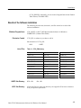
Table 1–2: GPIB board settings
271X
DMA Channel
NONE
IRQ
NONE
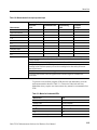
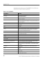
The following table lists how the 271X (both GPIB and RS-232 versions) needs
to be configured.
Table 1–3: 271X (Option 03) GPIB
Status
ONLINE
GPIB Address
11
Power On SRQ
ON or OFF
EOI/LF Mode
EOI
Talk Only Mode
OFF
1
1–4
This must be a unique address between 0 and 29
Cable TV RF Measurements Software for Windows User Manual
Installation
Table 1–4: 271X (Option 08) RS232
Status
ONLINE
Baud Rate
96001
Data Bits
8
Parity
NONE
EOL
LF
Flow Control
HARD (RTS/CTS)
Echo
OFF
Verbose
OFF
1
Device baud rate is selectable through the software
Connections menu. Other communications
parameters must be set to these values.
Upgrading From the MS-DOS Based Tektronix Cable TV Software
If you are not upgrading from the MS-DOS based Cable TV RF Measurements
Software, skip to Tutorial on page 2–1. If you are upgrading from the MS-DOS
based Cable TV RF Measurements Software, you must run the exportdb.exe
utility to transfer test results and channel tables from the MS-DOS based Cable
TV RF Measurements Software to the MS-Windows-based version of the same
software.
The Data Storage
Structure
This utility is necessary because the DOS- and Windows-based versions of the
software store their data differently. The DOS-based software stores all test
results and all channel table data together in four related database files. The
Windows-based software is oriented around worksheets (or spreadsheets). Each
worksheet is based on a single channel table and site combination. While several
worksheets may be based on the same channel table and site combination, a
single worksheet may not use more than one channel table and site.
This utility will scan each of the two pairs of DOS-based database files and
allow you to create data files and channel table files that are usable by the Cable
TV RF Measurements Software for Windows package.
Running the Utility
You should run the exportdb utility from the same directory in which your
Windows-based Cable TV Software is installed (probably 271X_SW). The
exported channel tables and data files will then be placed in that directory, which
is also the default location where the Windows-based Cable TV Software looks
for these files. In order to provide maximum protection for your existing data,
please perform the following operations (from the DOS command line) to copy
the four database files from the directory where your DOS-based Cable TV
Cable TV RF Measurements Software for Windows User Manual
1–5
Installation
Software is located to the directory in which your Windows-based Cable TV
Software is located. Then run exportdb.
CD C:\271X_SW (directory for the Windows-based CATV software)
COPY C:\CATV\SARESULT.DBF (This assumes that the DOS-based CATV)
COPY C:\CATV\SA_VALUE.DBF (software is installed in the C:\CATV)
COPY C:\CATV\CH_TBL.DBF (directory. If installed elsewhere,)
COPY C:\CATV\CHANNELS.DBF (use that directory instead.)
EXPORTDB
Since the source databases may contain a large number of channel tables and test
results, you may want to export test results only, channel tables only, or both.
The utility asks if you want to export any channel tables and then asks if you
want to export any measurement data. If you answer Y to both, then you will be
prompted whenever a new channel table is available to be exported and
whenever a new measurement data file is available to be exported. If you answer
N to either, then all prompts concerning that category will be skipped and
nothing in that category will be exported. For the categories you select, you can
also skip exporting individual channel table or data files.
The exportdb utility then verifies the integrity of the database files. It can export
from DOS-based Cable TV Software Version 1.1 and later.
Since there are usually test results from several sites that are based on the same
channel table, the databases are sorted first by the channel table name and then
by the test site.
When channel tables are exported and a new channel table name is encountered,
you are told the channel table name and asked for the DOS file name to which
you want it exported; the default extension is .CHT. You can then type a new
name or press the ESC key to skip exporting the channel table. As you type the
new name, the .CHT extension is overwritten (unless you press the Insert key
first, to get into Insert mode). For the file to have the .CHT extension, the
extension must appear in the name field when you accept the name.
As test results are exported, whenever the channel table name or the site name
changes, a new measurement data export file may be created. You are given the
channel table name and the site name on which the data is based and you are
asked for the DOS file name to which you want it exported; the default extension
is .WSR. You can then type a new name or press the ESC key to skip exporting
all data based on this channel table name and site name.
When channel tables are exported, it is possible to have channel tables available
for export that have no measurement data associated with them (in the DOSbased software, you can create channel tables without taking any measurements
based on them). It is also possible to have measurement data available based on
channel tables that are not available for export (in the DOS-based software, you
can delete channel tables from the databases after measurements based on them
have been stored).
1–6
Cable TV RF Measurements Software for Windows User Manual
Installation
In order for the exported channel tables to be used by the Windows-based
software, no additional action is required; they will appear in the list of available
channel tables. To use the exported data, first create a new worksheet based on
the same channel table that the data was based on. Then do File Import with the
Windows-based software and select the exported file you want to import and use.
You can import and use the exported data even if the channel table it is based on
is not available for export. In order to successfully import that data, the new
worksheet must be based on a channel table that contains the same channels as
the ones the tests were done on, and these must be analog channels (the
DOS-based Cable TV software does not support digital channels). For ease of
analyzing the resultant worksheet, the channel Frequency, Program Name and
Tag fields should also be the same.
Cable TV RF Measurements Software for Windows User Manual
1–7
Installation
1–8
Cable TV RF Measurements Software for Windows User Manual
Basic Tutorial
The goal of this chapter is to get you to the point where you are familiar with the
basic layout of a worksheet, can set up a worksheet, and can make simple
measurements.
Before beginning the tutorial, please check your hardware for the proper
connections. Double-checking the hardware will prevent errors that are hardware-related, making learning to use the Cable TV RF Measurements Software
for Windows that much easier.
If you want more information on an individual command, please refer to the
on-line help or to the Menu Bar section starting on page 3–11.
This tutorial assumes that a mouse is available. If a mouse is not available, make
selections using ALT+the underlined letter of the command.
By the end of this chapter, you should be able to do the following:
H
Select cells
H
Enter Worksheet Header information
H
Make simple measurements
H
Enter the Global View
H
Enter the Results Detail Display
H
Define a Measurement Sequence
H
Execute a Measurement Sequence
H
Define a Measurement Sequence using the Auto Selection buttons
H
View the broadcast picture on the computer monitor
H
Print out assorted reports
Cable TV RF Measurements Software for Windows User Manual
2–1
Basic Tutorial
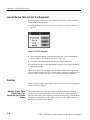
What Can the Cable TV RF Measurements Software for Windows Do?
The purpose of the software application is to do the time-consuming and tedious
tasks of measuring and recording the results of measurements associated with a
cable TV system. To make a measurement on a particular channel, simply select
the cell where the channel and measurement intersect and double-click the left
mouse button. The results are printed in the cell. Print out the reports and the job
is completed. Of course, this is a cable system and there are many channels and
many measurements. The software allows you to make many measurements
rapidly by selecting several channels or measurements.
Start the Cable TV RF Measurements Software for Windows
1. Start the Windows program.
2. Find the icon for the Tektronix Cable TV RF Measurements Software for
Windows (created during installation).
Mouse
Keyboard
Double click on the icon to start the application.
Enter the window with the software icon in it
by pressing ALT+w, highlight the correct
window, then press ENTER. Press the arrow
keys to highlight the software icon, then press
ENTER to start the application.
The initial display is called a worksheet. The worksheet will be blank except for
the measurement list running across the top row and a channel list running down
the left column.
2–2
Cable TV RF Measurements Software for Windows User Manual
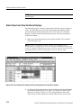
Basic Tutorial
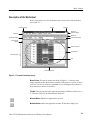
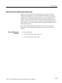
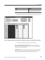
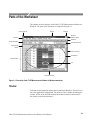
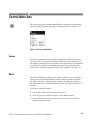
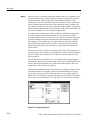
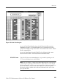
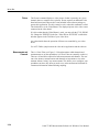
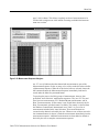
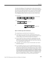
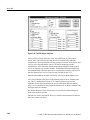
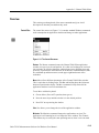
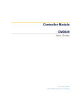
Description of the Worksheet
Now is a good time to review the names for the various parts of the worksheet.
(See Figure 2–1.)
Control menu box
Title bar
Minimize
Restore or
maximize button
Menu bar
Button bar
Worksheet header
View filter status box
Measurement
header
Vertical scroll bar
Spreadsheet
Channel header
Cell
Horizontal scroll bar
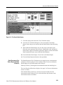
Figure 2–1: The default worksheet display
Mouse Pointer. The mouse pointer (not shown in Figure 2–1) can take many
shapes, dependent upon the functions available. If the pointer is a cross, it selects
cells. If it is an arrow, it chooses commands. If it is an hourglass, the software is
busy and no new actions are available.
Title Bar. This lists the title of the application running in Windows. In this case, it
is “Tektronix Cable TV RF Measurements Software”.
Minimize Button. Shrinks the application to an icon.
Maximize Button. Makes the application window fill the entire display area.
Cable TV RF Measurements Software for Windows User Manual
2–3
Basic Tutorial
Restore Button. Returns the application window to its previous size.
Control Menu Box. Contains the standard Windows commands: Restore, Move,
Size, Minimize, Maximize, Close, and Switch To.
Channel Header. Lists channels.
Measurement Header. Lists measurements.
Vertical Scroll Bar. Used to move the spreadsheet vertically. Note that the
Measurement Header remains along the top as a reference.
Horizontal Scroll Bar. Moves the spreadsheet horizontally. Note that the Channel
Header remains along the side as a reference.
Menu Bar. Contains all of the software menus: File, Edit, View, Measure,
Configure, Execute, and Help.
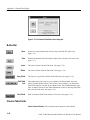
Button Bar. Contains the command buttons. The command buttons are shortcuts
with equivalents in the Menu Bar. The command buttons are: Open, Save,
Global, Results, Status, Meas Sel, Meas Seq, Test ID, Setups, Limits, and Print.
Spreadsheet. Contains all of the cells, the Measurement Headers, and the
Channel Headers.
Cell. One small box on the spreadsheet — the intersection of one measurement
and one channel.
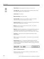
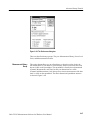
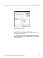
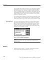
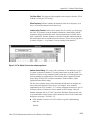
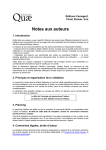
Worksheet Header. Figure 2–2 illustrates the Worksheet Header which lists
important information about a worksheet. Edit this information in various ways
depending upon which piece you would like to change. (See page 2–14 for how
to set up a worksheet.)
Figure 2–2: The Worksheet Header
Worksheet. The name of the current worksheet. It is called <untitled> if the
worksheet has not been saved.
2–4
Cable TV RF Measurements Software for Windows User Manual
Basic Tutorial
Chan Table. This file lists the channels in the system under test. There must be a
Channel Table or the software will not run.
Site. An additional identifier for the worksheet. Site is intended to be the
location where the measurement takes place. Only one Site is allowed for each
worksheet. <undefined> is a valid Site name.
Test ID. This is the name or ID of the person who is making the measurements,
the measurement test point, or any other identifier that might be appropriate. A
single worksheet can have multiple Test IDs. It sub-divides measurements made
at a single Site (such as Pre-converter and Post-converter). <undefined> is a
valid Test ID name.
View Filter Status Box. This tells how much of the spreadsheet is in view or
available. The options for the box are: “No View Filter is On” (the entire
spreadsheet is in view); “View Selected Filter is On” (display only selected
measurements and channels); “View Sequence Filter is On” (display only
measurements made with a Measurement Sequence); and “View Test ID Filter is
On” (display only measurements made with the current Test ID). Only measurements and channels “in view” are available for measurements.
Navigation
The following section explains how to get around in the software. All actions are
first explained for the mouse and then for the keyboard. If you are familiar with
Windows command selection, skip to Scroll Through the Spreadsheet on
page 2–9.
Choose from the
Menu Bar
Step
Mouse
Keyboard
1
Single-click the left mouse button on the
desired menu from the Menu Bar.
Press ALT+the underlined letter in the
menu.
2
Single-click the left mouse button on the
desired command.
Press the underlined letter for the desired
command or use the arrow key to scroll,
then press Enter.
Cable TV RF Measurements Software for Windows User Manual
2–5
Basic Tutorial
Example: Open a Worksheet
Step
Mouse
Keyboard
1
Single-click the left mouse button on the
word “File” on the Menu Bar.
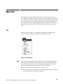
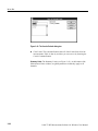
Press ALT+f.
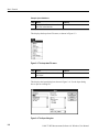
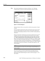
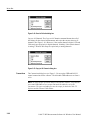
This displays the drop-down File menu, as shown in Figure 2–3.
Figure 2–3: The drop-down File menu
Step
Mouse
Keyboard
2
Single-click the left mouse button on the
word “Open”.
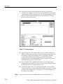
Press o.
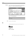
This displays the Open dialog box shown in Figure 2–4. Use the Open dialog
box to open an existing file.
Figure 2–4: The Open dialog box
2–6
Cable TV RF Measurements Software for Windows User Manual
Basic Tutorial
Choose from the
Button Bar
Step
Mouse
Keyboard
3
Single-click the left mouse button on the
Cancel command button to close the Open
dialog box without opening a file.
Press ESC to close the Open dialog box
without making any changes.
Mouse
Keyboard
Single-click the left mouse button on the
desired command button.
Press ALT+the underlined letter from the
command button.
or
Press TAB to place the cursor on the Button
Bar, then press either TAB or the arrow keys to
select the command button. (Be careful using
the arrow keys. They will scroll off the Button
Bar and into the spreadsheet.) Press ENTER
to choose the selected command button.
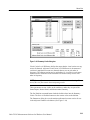
Example: Open the Test ID Dialog Box
Step
Mouse
Keyboard
1
Single-click the left mouse button on the
Test ID command button.
Press ALT+i.
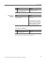
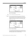
This displays the Test ID dialog box as shown in Figure 2–5.
Cable TV RF Measurements Software for Windows User Manual
2–7
Basic Tutorial
Figure 2–5: The Test ID dialog box
Special Command Button
Keyboard Shortcuts
Step
Mouse
Keyboard
2
Single-click the left mouse button on the
Cancel command button, to close the
dialog box without making any changes.
Press ESC.
Many dialog boxes have two special command buttons: OK and Cancel.
To choose OK from the keyboard, press ENTER with anything highlighted
except the Cancel button.
To choose Cancel from the Keyboard either press ESC or press TAB until the
Cancel command button is highlighted, then press ENTER.
2–8
Cable TV RF Measurements Software for Windows User Manual
Basic Tutorial
Scroll Through the
Spreadsheet
Mouse
Keyboard
Either:
Place the cursor in the spreadsheet. (Use the
arrow keys if you are on the Button Bar or
ESC if you are on the Menu Bar.) Use the
arrow keys to scroll the spreadsheet to the
desired position. The spreadsheet display will
move every time you move to a cell that is off
screen. The HOME, END, PAGE UP, and
PAGE DOWN are also available to move
quickly through the spreadsheet.
Click on the left, right, up, or down scroll
arrows in the Vertical or Horizontal Scroll Bar
with the left mouse button. This scrolls the
spreadsheet one cell at a time.
or
Click on the scroll box in the Vertical or
Horizontal Scroll Bar with the left mouse
button, then hold down the left mouse button
and drag the scroll box to the desired position.
Release the mouse button.
HOME. Moves to the first cell in the current
channel.
END. Moves to the last cell in the current row
that has a measurement made for any
channel.
PAGE UP. Moves the spreadsheet up one
page. (Measurement stays the same and the
current channel is the first channel that is at
the top of the screen.) Nothing happens if the
top channel is currently visible.
PAGE DOWN. Moves the spreadsheet down
one page. (Measurement stays the same and
the current channel is the last channel that is
at the bottom of the screen.) Nothing happens
if the bottom channel is currently selected.
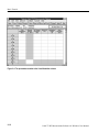
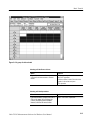
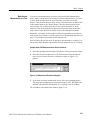
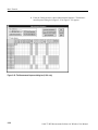
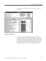
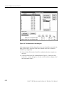
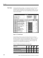
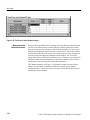
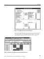
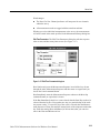
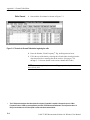
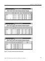
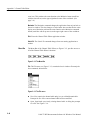
Example: Display the Cross Modulation measurement for channel 3
Step
Mouse
Keyboard
1
Click on the Horizontal Scroll Bar box with
the left mouse button. Hold down the left
mouse button and drag the cursor until it is
all the way to the right side of the Horizontal Scroll Bar. The Cross Modulation
column is visible.
Place the cursor on the spreadsheet.
Press the right arrow key until the Cross
Modulation column is visible.
2
Click on the Vertical Scroll Bar up arrow
with the left mouse button until channel 4
(the second channel in the example) is
visible. The spreadsheet looks similar to
the on shown in Figure 2–6. Notice the
position of the boxes in the Vertical and
Horizontal Scroll Bar.
Press the down arrow key until your
second channel (channel 4 in the example)
is visible. The spreadsheet looks similar to
Figure 2–6. The Cross Modulation cell for
channel 4 is selected (using the std.cht
Channel Table). Notice the position of the
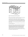
boxes in the Vertical and Horizontal Scroll
Bar.
3
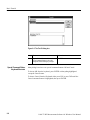
Reverse the steps to return to the spreadsheet to display the first column.
Cable TV RF Measurements Software for Windows User Manual
2–9
Basic Tutorial
Figure 2–6: The spreadsheet scrolled to the Cross Modulation column
2–10
Cable TV RF Measurements Software for Windows User Manual
Basic Tutorial
Select a Cell from the
Spreadsheet
Mouse
Keyboard
Single-click the left mouse button on the
desired cell.
Press ESC or the arrow keys until the cursor is
in the spreadsheet. Use the arrow keys to
move the cell outline to the desired cell.
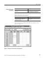
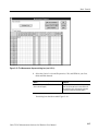
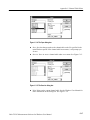
Example: Select channel 4’s carrier to noise cell
Mouse
Keyboard
Place the mouse cursor anywhere in the cell.
Single-click the left mouse button. The
selected cell is outlined.
Use the arrow keys to move the cell outline to
the desired cell.
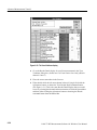
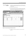
The selected cell on the spreadsheet looks similar to the Channel 4 Carrier to
Noise cell in Figure 2–7.
Figure 2–7: Example of a cell selected on the spreadsheet
Cable TV RF Measurements Software for Windows User Manual
2–11
Basic Tutorial
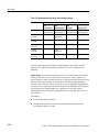
Select a Group of Cells
Note that you can only select adjacent cells (rows, columns, or blocks). If
non-adjacent cells need to be measured as a group use a Measurement Sequence
(see page 2–25).
Step
Mouse
Keyboard
1
Click on one of the corner cells in the
desired group.
Press the arrow keys until one corner cell
of the desired group is selected.
2
Hold down the left mouse button and
drag the mouse until all of the desired
cells have reversed color. (When the cell
color reverses, it indicates selection. The
first cell does not reverse color.)
Hold down the SHIFT button. Use the
arrow keys to move around the spreadsheet until the desired group of cells has
reversed color. (When a cell reverses
color — it has been selected. The first
cell does not reverse color.)
3
Release the left mouse button.
Release the SHIFT button.
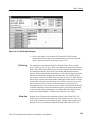
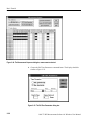
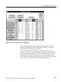
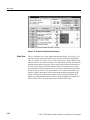
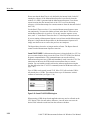
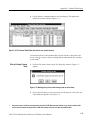
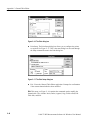
Example: Select carrier levels and frequencies for channels 3-5
Step
Mouse
Keyboard
1
Single-click on the Visual Carrier Level
cell for the second channel (channel 3).
Use the arrow keys to place the cursor
around the Visual Carrier Level cell for
the second channel (Channel 3).
2
Start the mouse pointer in the selected
cell, then hold down the left mouse button
and drag the mouse cursor until the
desired cells have reversed color.
Release the left mouse button. The
selected cells keep the reversed color,
except for the original corner cell which is
outlined.
Hold down the SHIFT key and use the
arrow keys to select the desired cells.
The selected cells reverse color, except
for the original corner cell which is
outlined.
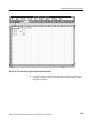
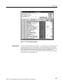
The spreadsheet resembles Figure 2–8. Note that the selected cells have reversed
in color except for the corner cell which is outlined.
2–12
Cable TV RF Measurements Software for Windows User Manual
Basic Tutorial
Figure 2–8: A group of cells selected
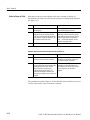
Selecting an Entire Row or Column
Mouse
Keyboard
Single-click on the name of the measurement
or channel in the Measurement or Channel
Header.
Place the cursor anywhere in the row and
press SHIFT+spacebar.
To Select an Entire Column. Place the cursor
anywhere in the column and press
CTRL+spacebar.
Selecting an Entire Spreadsheet
Mouse
Keyboard
From the Edit menu, choose Select All or
Click on the upper left cell (where the
Channel and Measurement Headers
intersect) with the left mouse button.
Press CTRL+SHIFT+spacebar.
Cable TV RF Measurements Software for Windows User Manual
2–13
Basic Tutorial
NOTE. From now on the act of selecting cells is referred to as:
Select XX cells from the spreadsheet, where XX defines the exact cells needed.
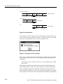
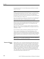
Set Up a Worksheet
Create a new worksheet for practice. There are four parts to a worksheet
definition: Site, Test ID, Channel Table, and Worksheet name. The Worksheet is
the main file that stores everything. Each Worksheet may only have one Site and
one Channel Table associated with it. If the Channel Table or Site changes, the
software automatically gives you the option to start a new worksheet or rename
the Site in the current worksheet.
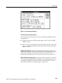
Enter a Site and
Description
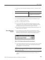
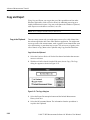
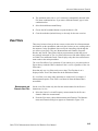
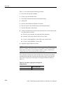
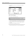
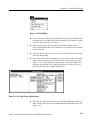
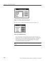
1. From the File menu, select New. If there was a worksheet already defined,
the following Warning dialog box (Figure 2–9) is displayed:
Figure 2–9: Warning dialog box
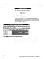
2. Do not save the old worksheet — choose the No command button.
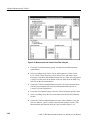
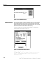
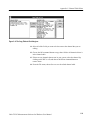
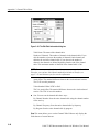
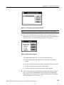
This displays the New dialog box, as shown in Figure 2–10.
2–14
Cable TV RF Measurements Software for Windows User Manual
Basic Tutorial
Figure 2–10: The New dialog box
3. Select the Site combination box.
Mouse
Keyboard
Click on the Site combination box.
Press TAB until the cursor is blinking in the
Site list box.
4. Select a Site name. (The example uses “Tektronix – Beaverton”.)
Mouse
Keyboard
Type in your Site name or click on the arrow
box to select a Site name from the combination box. (Use a site name appropriate for your
setup.)
Type in your Site name or press the up or
down arrow keys to select a Site name from
the combination box.
5. Select the Description text box.
Mouse
Keyboard
Click the left button in the Description text box.
Press ALT+p or TAB.
Cable TV RF Measurements Software for Windows User Manual
2–15
Basic Tutorial
6. Enter the description: “This worksheet is for practice only.”
7. Select std.cht as the Channel Table by clicking on std.cht in the list box.
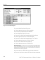
8. Leave the New dialog box and save the changes, by choosing the OK
command button.
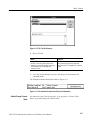
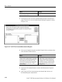
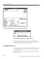
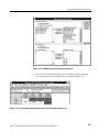
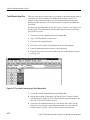
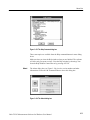
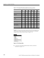
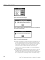
9. From the File menu, choose Save As. The Save As dialog box appears, as
shown in Figure 2–11.
Figure 2–11: The Save As dialog box
10. In the File Name combination box type: “example”.
11. Choose the OK command button. The file name “example.wrk” is in the
Worksheet Header.
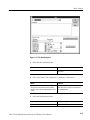
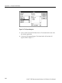
Enter a Test ID
2–16
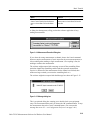
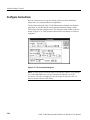
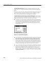
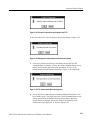
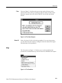
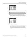
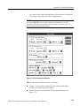
1. From the Configure Menu, select Test ID or choose the Test ID command
button from the Button Bar. This displays the Test ID dialog box, as shown
in Figure 2–12.
Cable TV RF Measurements Software for Windows User Manual
Basic Tutorial
Figure 2–12: The Test ID dialog box
2. Select a Test ID.
Mouse
Keyboard
Type in a Test ID or select from the combination box: click on the arrow (if present and
necessary) in the list box and then select one
Test ID from the list. The example uses
“Learner’s Permit”.
Type in the Test ID or select one from the list
box by scrolling through the list (press the
down arrow key). The example uses “Learner’s
Permit”.
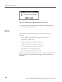
3. Leave the Test ID dialog box and save the changes by choosing the OK
command button.
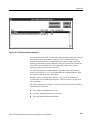
The Worksheet Header should look similar to Figure 2–13.
Figure 2–13: The worksheet header after filling in all information
Attach/Change Channel
Table
See Advanced Setups Tutorial on page 2–39 or Appendix C: Channel Table
Editor, if you must change the Channel Table.
Cable TV RF Measurements Software for Windows User Manual
2–17
Basic Tutorial
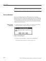
Make Simple Measurements
You now have enough background to begin making simple measurements and
you have created a new worksheet so you will not overwrite an existing one.
NOTE. Do not use the 2714 (and early 2715s) to take digital measurements. The
2714 will not take digital measurements (Average Power, Desired To Undesired,
and Adjacent Channel Leakage), but uses the same channel table format as the
2715. If the software attempts to take a digital measurement using the 2714,
measurements returned will be incorrect, errors will be returned, or the software
will behave unpredictably.
One Measurement for
One Channel
To make one measurement on one channel, select a cell. From the Measure
menu, choose Current Selection (or choose Meas Sel from the Button Bar).
or
Mouse
Keyboard
Double-click on a cell with the left mouse
button.
Press ESC or the arrow keys until the cursor is
in the spreadsheet. Use the arrow keys to
move the cell outline to the desired cell, then
press Enter.
The measurement results appear in the cell, replacing any previous results. (The
previous results are not necessarily lost. See Configuration Preferences on
page 2–46.)
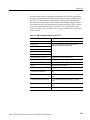
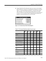
Only one measurement on one channel takes place, unless you select one of the
first six measurements: Visual Carrier Level, Visual Carrier Frequency, Aural
Carrier Level, Aural Frequency Offset, Second Aural Level, and Second Aural
Frequency Offset. Select any of these cells and all six measurements always take
place.
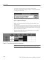
Example: Measure Carrier Levels and Frequencies for the First Channel.
Mouse
Keyboard
Select the cell by single-clicking the left mouse
button.
Place the cursor in the spreadsheet, then use
the arrow keys to select the cell.
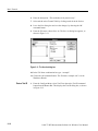
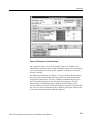
Execute the measurement.
2–18
Cable TV RF Measurements Software for Windows User Manual
Basic Tutorial
Mouse
Keyboard
Either double-click with the left mouse button,
choose Current Selection from the Measure
menu, or choose Meas Sel from the Button
Bar.
Either choose Current Selection from the
Measure menu or choose Meas Sel from the
Button Bar.
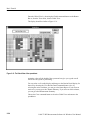
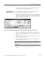
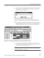
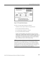
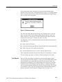
A dialog box then appears, telling you that the software application is busy
making measurements.
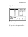
Figure 2–14: Measurement Execution Dialog box
If you chose the wrong measurement or channel, choose the Cancel command
button to stop the measurement. (Cancel stops after the current measurement, so
it does nothing when making a single measurement.) If everything is fine, do
nothing to continue the measurement.
The software might respond with a message to turn off the scrambling if that
particular channel has scrambling enabled and the requested measurement
requires it. (When all of the measurements for the channel are finished, then
another message reminds you to turn the scrambling back on.)
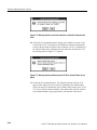
The software might also respond with the Message box shown in Figure 2–15.
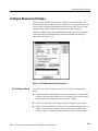
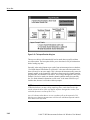
Figure 2–15: Message dialog box
This is an optional dialog box warning you to double check your equipment
setup. The measurement halts until you choose the OK command button. To stop
the measurement choose the Cancel command button. (You can turn this
message box on or off — see Configuration Preferences on page 2–46.)
Cable TV RF Measurements Software for Windows User Manual
2–19
Basic Tutorial
If everything is properly connected, select the OK command button.
The software responds with the dialog box in Figure 2–16 to let you know that it
is working on the measurement.
Figure 2–16: Measurement Dialog box
Again, you can cancel the measurement at this point by choosing the Cancel
command button.
The software fills in the first four or six cells for the selected channel. (There are
only four measurements made in the following example because std.cht does not
have the Second Aural Frequency set. If the Channel Table has a value, then the
last two measurements are available.)
Repeat this measurement for the next two channels on the list. The resulting
spreadsheet looks similar to Figure 2–17.
Figure 2–17: The spreadsheet after making a few measurements
NOTE. From now on the above steps required to make a measurement on a
selected cell is referred to as: Make the XX measurements on the XX channels.
2–20
Cable TV RF Measurements Software for Windows User Manual
Basic Tutorial
Make Several
Measurements at a Time
To make several measurements: select the cells, then from the Measurement
menu, choose Current Selection (or Meas Sel from the Button Bar). If you want
to make all the measurements for a given channel, select the row for that
channel. Then from the Measure menu, choose Current Selection or double-click
on the channel name in the Channel Header. This takes measurements on the
entire channel. Use a similar procedure to take one measurement for all the
channels: select all the channels for that measurement, then from the Measure
menu, chose Current Selection or double-click on the Measurement Header.
Remember, you cannot use this method to make measurements on non-adjacent
cells because they cannot be selected together. Use a Measurement Sequence (see
page 2–25) to make measurements on non-adjacent cells.
Since it usually takes a little while for groups of measurements to complete, you
can switch to other Windows applications while the measurements are executing.
Example: Make CSO Measurements for Several Channels.
1. Scroll the spreadsheet horizontally to display the CSO measurement column.
2. Select the first three channels for a CSO measurement. From the Measure
menu, choose Current Selection. A dialog box similar to Figure 2–18
appears.
Figure 2–18: Measurement Execution dialog box
3. If you need to stop the measurement, choose the Cancel command button.
This stops after completing the current measurement. (ESC, RETURN, and
spacebar will cancel the measurement.) If everything is fine, do nothing.
The spreadsheet cells should look similar to Figure 2–19.
Cable TV RF Measurements Software for Windows User Manual
2–21
Basic Tutorial
Figure 2–19: The spreadsheet cells after making a group of measurements
Notice that this measurement only gives the worst-case numerical results. There
are several separate measurements under this Measurement Header and there is
not enough room to report all of the results in a single cell. The measurements
under this measurement heading are: CSO measurements at up to five different
locations.
What if you want to see the individual results of each of these measurements?
You enter the Results Detail Display.
Results Detail Display
The Results Detail Display gives more information than a single cell could hold.
There are three ways to enter a Results Detail Display for the cell:
H
Single click on the cell using the RIGHT mouse button.
H
Select a cell, then choose the Results command button from the Button Bar.
H
Select a cell, then from the View menu, choose Results Detail.
Example: Results Detail for CSO for Channel 2.
1. Select the CSO measurement cell for channel 2.
2. Choose the Results command button from the Button Bar. See Figure 2–20
for the dialog box.
2–22
Cable TV RF Measurements Software for Windows User Manual
Basic Tutorial
Figure 2–20: The Results Detail dialog box
3. Scroll to the right to view the Date & Time and the Test ID for these
measurements. Choose the Close command button to return to the spreadsheet. (Also see Results Detail Display on page 2–54.)
Cell Coloring
Global View
You might have noticed that the cells have different colors. They are white,
green, yellow, red, blue, or gray. These colors indicate the range of the measurement results. White means that there are no limits assigned to that measurement
or no measurements have been made. Green means that the measurement is
passing. Yellow means that the measurement is in the caution range. Red means
that the measurement has dropped into the alarm state. The limits file defines
these ranges. Limits are covered in Defining Limits on page 2–71. Blue indicates
that an error occurred in the measurement, making the results invalid. All of the
results in the cell must be in error for the cell to be blue, otherwise the cell will
take on the color of the worst case valid measurement. Gray cells have no
measurement results. Any cell that is grayed is either not included in the transfer
to the RF instrument, or the measurement can not be performed on the channel
(you cannot take analog measurements on a digital channel or digital measurements on an analog channel). Therefore, they cannot have any results.
Another way of looking at the measurement results is the Global View. This
display shows all of the measurements for many channels at a time. This view
does not give numerical results rather only pass, warning, alarm, unknown/not
defined, or error-in-measurement indications based on the color of the cells.
Cable TV RF Measurements Software for Windows User Manual
2–23
Basic Tutorial
Enter the Global View by choosing the Global command button on the Button
Bar or, from the View menu, choose Global View.
The display should be similar to Figure 2–21.
Figure 2–21: The Global View of the spreadsheet
Again the colors tell the health of the system and can give you a good overall
feel of how the system is performing.
You can select a cell on this display and then go to the Results Detail display for
that cell by choosing the View Results Detail command button. Also, by
selecting the entire worksheet, you can go to the Status Report. If you select an
entire row, you can go to the Channel Summary. If you select an entire column,
you can go to the Measurement Summary.
Choose the Close command button to close the Global View and return to the
spreadsheet.
2–24
Cable TV RF Measurements Software for Windows User Manual
Basic Tutorial
Define and Use a Measurement Sequence
Suppose you need to make several measurements on a couple of different
channels on a regular basis. These measurements and channels are not close
enough on the worksheet to select the cells and use Current Selection from the
Measure menu. To make these measurements you can use a Measurement
Sequence. A Measurement Sequence is a list of measurements that you define
and run whenever you need. You can only define one Measurement Sequence at
a time, so there is no confusion about what measurements and channels are in a
Measurement Sequence.
Now define a simple Measurement Sequence to make Carrier Levels and
Frequencies, CSO, and HUM measurements for your first, third, and fifth
channels.
Define a Measurement
Sequence
1. Clear the spreadsheet.
a. From the Edit menu, choose Select All.
b. From the Edit menu, choose Clear.
Cable TV RF Measurements Software for Windows User Manual
2–25
Basic Tutorial
2. From the Configure menu, choose Measurement Sequence. The Measurement Sequence dialog box (Figure 2–22 or Figure 2–23) appears:
Figure 2–22: The Measurement Sequence dialog box (U.S.A. only)
2–26
Cable TV RF Measurements Software for Windows User Manual
Basic Tutorial
Figure 2–23: The Measurement Sequence dialog box (non–U.S.A.)
3. Select the Carrier Levels and Frequencies, CSO, and HUM for your first,
third, and fifth channels.
Mouse
Keyboard
Double-click those cells. (To deselect: double
click on the cell again.)
Press TAB until the cursor is in the spreadsheet. Use the arrow keys to move to the cell,
then select the cell by pressing the spacebar.
(To deselect: press the spacebar again.)
Your dialog box should resemble Figure 2–24.
Cable TV RF Measurements Software for Windows User Manual
2–27
Basic Tutorial
Figure 2–24: The Measurement Sequence dialog box, measurements selected
4. Choose the Edit Time Parameters command button. The display should be
similar to Figure 2–25.
Figure 2–25: The Edit Time Parameters dialog box
2–28
Cable TV RF Measurements Software for Windows User Manual
Basic Tutorial
5. If necessary, deselect the Run Continuously check box. To deselect a check
box:
Mouse
Keyboard
Click on the Run Continuously check box.
Press TAB until the cursor is around the Run
Continuously box, then press the spacebar to
deselect that check box (or use ALT+the
letter).
6. Select the Run Immediately check box from the Time Parameters group.
7. Enter “1” in the Run N Times text box.
8. Enter “0” in the Repeat Interval text box.
9. The rest of the options in the Edit Time Parameters dialog box are gray,
indicating they are not available. Choose the OK command button to save
the changes and return to the Measurement Sequence dialog box.
10. Choose the OK command button to accept the Measurement Sequence. The
display returns to the worksheet.
Run the Measurement
Sequence
1. Choose the Meas Seq command button from the Button Bar, or choose
Sequence from the Measure menu. The dialog box in Figure 2–26 appears,
that telling you that the software is running a measurement sequence.
Figure 2–26: The Sequence Measurement Execution dialog box
2. If you want the Measurement Sequence to stop, choose the Cancel command
button, otherwise allow the sequence to run. The Measurement Sequence
runs through once. (It will take a while.)
NOTE. You can change to another Windows application while the Measurement
Sequence is running. When the sequence is complete, the software automatically
becomes the active window.
At the end of the Measurement Sequence the dialog box in Figure 2–27
appears.
Cable TV RF Measurements Software for Windows User Manual
2–29
Basic Tutorial
Figure 2–27: View Filter Warning dialog box
3. Choose the Yes command button. Now only the measurements made with
the Measurement Sequence are visible and the View Filter box says that the
Measurement Sequence View Filter is on (Figure 2–28). (For more information on View Filters see page 2–65.)
Figure 2–28: Measurement Sequence results with view filter on
4. Choose Measurement Sequence Results from the View menu to turn the
Measurement Sequence View Filter off and return to a normal display.
2–30
Cable TV RF Measurements Software for Windows User Manual
Basic Tutorial
Measurement Sequences
Using Auto Selection
You may have noticed a group in the Measurement Sequence dialog box labeled
Auto Selection. These four buttons allow you to quickly set up a Measurement
Sequence that might be run on a regular basis. The four buttons are: FCC
Pre-Converter, FCC Post-Converter, FCC Headend Msmts, and 24 Hour Test.
You may add other measurements before or after choosing an Auto Selection
command button.
NOTE. Non-U.S.A. countries have only the 24 Hour Test button available,
because the rest of the Auto Selection buttons are for making FCC (a U.S.A.
regulatory agency) required measurements.
Table 2–1 lists the measurements available under the Auto Selection command
buttons. They all have Carrier Levels and Frequencies for all channels. Other
measurements are for user-selected channels only.
Table 2–1: Measurements Taken by Auto Selection buttons
Auto Selection Button
FCC
Pre-Converter
FCC
Post-Converter
FCC
Headend
24 Hour Test1
All Channels
Carrier Levels
and Frequencies
Carrier Levels
and Frequencies
Carrier Levels
and Frequencies
Carrier Levels
and Frequencies
Selected
Channels
ICR
Carrier to
Noise Ratio
Selected
Channels
CSO
Selected
Channels
CTB
Selected
Channels
Cross
Modulation
Selected
Channels
Hum
1
The 24 Hour Test automatically includes 4 repetitions at 6 hour intervals.
Set Up an Auto Selection Measurement Sequence.
1. From the Configure menu, choose Measurement Sequence. The Measurement Sequence dialog box appears.
2. Choose the Clear Sequence command button to erase any old Measurement
Sequence information.
Cable TV RF Measurements Software for Windows User Manual
2–31
Basic Tutorial
Mouse
Keyboard
Click on the Clear Sequence command button
with the left mouse button.
Press ALT+c.
3. Choose the FCC Pre-Converter command button from the Auto Selection
group. The FCC Pre-Converter Measurements dialog box appears as shown
in Figure 2–29.
Figure 2–29: The FCC Pre-Converter Measurements dialog box
4. Select several channels from the Available Channels list box and place them
in the Selected Channels list box.
Mouse
Keyboard
Double-click the left mouse button on the
channel name for single channels. For several
channels, click on the first channel with the left
mouse button, then hold down SHIFT and
click on the last channel in the list with the left
mouse button. Then choose the <–Select
command button.
Press TAB until the cursor is in the Available
Channels list box. Use the arrow keys to select
a channel or to select several channels at a
time hold down SHIFT while moving through
the list with the arrow keys. Add the selected
channel(s) to the Selected Channels list box
by pressing ALT+e.
5. Choose the OK command button to return to the Measurement Sequence
dialog box.
6. Add a Carrier to Noise measurement to the channels that also have an
In-Channel Response measurement.
2–32
Cable TV RF Measurements Software for Windows User Manual
Basic Tutorial
Mouse
Keyboard
Double-click those cells with the left mouse
button.
Press TAB until the cursor is in the spreadsheet. Use the arrow keys to move to the cell,
then select the cell by pressing the spacebar.
The Measurement Sequence dialog box should look similar to Figure 2–30.
Figure 2–30: Measurement Sequence dialog box after Auto Selection command and a few additional measurements
7. Choose the OK command button to return to the spreadsheet.
Run an Auto Selection Measurement Sequence. You run the Auto Selection
Measurement Sequence in the same way that you run any other Measurement
Sequence. It requires nothing special.
Carrier Survey. The Carrier Survey check box allows you to quickly select all of
the Carrier Level and Frequency measurements and Average Power measurements. More details are available in Current Selection on page 3–39.
Cable TV RF Measurements Software for Windows User Manual
2–33
Basic Tutorial
Display the Picture (Optional)
There will be times that you want to see what the broadcast signal looks like
while you are making measurements on it. For example, your first channel just
miserably failed its last FCC Measurements check and you would like to see the
amount of picture distortion. The software can show you the picture directly on
the computer screen if you have a video board and driver installed (see Picture
on page 3–34).
Use the following procedure to display your first channel:
1. From the control menu box, use Switch To to go to the Windows Program
Manager.
2. Start your video driver.
3. Return to the software application.
4. Configure your equipment to provide the desired video signal to the video
card in your computer.
5. From the View menu, choose Picture. The picture is displayed on the
computer screen.
6. To leave the Picture display from the control menu box in the picture
window, choose Close. Or you can hide the picture by clicking anywhere in
the software application window.
Print (Optional)
Now that you have some data to look at, it is time to print out some worksheets
and reports.
1. Check your printer setups. From the File menu, choose Print Setup. The
Print Setup dialog box appears as shown in Figure 2–31.
2–34
Cable TV RF Measurements Software for Windows User Manual
Basic Tutorial
Figure 2–31: The Print Setup dialog box
This dialog box is identical to the standard Windows Print Setup dialog box.
(Use the Windows 3.1 User’s Guide and on-line help for any problems.) When
the printer is set correctly, choose the OK command button. The printer is now
ready to use.
NOTE. As a general rule, use landscape orientation for easier to read reports.
2. From the File menu, choose Print. The dialog box shown in Figure 2–32
appears.
Figure 2–32: The Print dialog box
Cable TV RF Measurements Software for Windows User Manual
2–35
Basic Tutorial
3. Select your needed options and then choose OK to print.
NOTE. Before printing out a worksheet, select the View Used option from
Measurements and Channels in the View menu. This will automatically limit the
display to measurements and channels that have results.
Print Out the Worksheet
Choose the Print command button on the Button Bar. The entire worksheet
prints.
NOTE. The print dialog box has a special check box, Expand Columns. This
option allows all of the measurements that would normally only show Pass,
Caution, or Alarm to expand, giving all of the numerical results. The columns
that expand are: CSO, CTB, and HUM/LFD.
Print Out the Results
Detail Display
1. Display the Results Detail for the first channel of the measurement. (Select
the cell, then click on the Results button on the Button Bar or click on the
cell with the right mouse button.)
2. Choose the Print command button in the Results Detail Display.
3. Leave the Results Detail Display by choosing the Close command button.
End of the Tutorial
You have just completed the basic Tutorial for the software. At this point, you
should be able to do the following:
2–36
H
Select cells. (See page 2–11.)
H
Enter Worksheet Header information. (See page 2–14.)
H
Make simple measurements. (See page 2–18.)
H
Enter the Results Detail Display. (See page 2–22.)
H
Enter the Global View. (See page 2–23.)
H
Define a Measurement Sequence. (See page 2–25.)
H
Run a Measurement Sequence. (See page 2–29.)
H
Define a Measurement Sequence using the Auto Selection buttons. (See
page 2–31.)
Cable TV RF Measurements Software for Windows User Manual
Basic Tutorial
H
View what is being broadcast on the computer monitor. (See page 2–34.)
H
Set up your printer. (See page 2–34.)
H
Print out assorted reports. (See page 2–36.)
The next chapters are about advanced topics and build on the above information.
If you are not comfortable with any of the above topics, please go back and
review them before beginning on the advanced topics.
Cable TV RF Measurements Software for Windows User Manual
2–37
Basic Tutorial
2–38
Cable TV RF Measurements Software for Windows User Manual
Advanced Setups Tutorial
This chapter explains how to set up your system to give you only the information
that you want and to make the most accurate measurements. The following
topics are covered:
H
Review the correct RS-232 and GPIB connections
H
Set the 271X controls
H
Select how the measurements are made
H
Change to a different Channel Table
H
Select whether or not to collect history
H
Select the Power Level Units
H
Turn the user prompts and alarm messages on or off
Cable TV RF Measurements Software for Windows User Manual
2–39
Advanced Setups Tutorial
Configure Connections
How the Connections are set up was already touched on in the Installation
chapter but it is re-explained here for completeness.
The first time running the Cable TV RF Measurements Software for Windows
application, or any time that the test equipment connections change, choose
Connections from the Configure menu. The dialog box looks similar to the one
shown in Figure 2–33. Verify that the software knows the addresses of the test
equipment.
Figure 2–33: The Connections dialog box
NOTE. To ensure proper operation and prevent software conflicts, verify that all
ports and GPIB addresses are unique and match the addresses set in the
instruments. The ports and addresses must be unique for both the Cable TV
Software and the Channel Table Editor.
2–40
Cable TV RF Measurements Software for Windows User Manual
Advanced Setups Tutorial
Configure Measurement Setups
There are many different ways that your system can run measurements. The
Measurement Setups dialog box tells the software how your system needs to be
set up in order to make measurements and get the best results. There are setup
parameters that affect all channels and some that are channel specific.
From the Configure menu, choose Measurement Setups, or choose the Setups
command button from the Button Bar. The Measurement Setups dialog box
looks similar to Figure 2–34:
Figure 2–34: The Measurement Setups dialog box
The All Channels Group
Use the 2714/2715 Sub-Group to set up a 2714 or 2715 for taking measurements:
H
External Attenuation/Amplification. Enter the attenuation or amplification
(in dB) of the test point in this text box. For example: if the measurements
are being made at a 10 dB down test point, enter –10 dB.
H
Power Line Frequency. This is the power line frequency of your system.
H
Preamp. The Preamp allows increased sensitivity when measuring low level
signals. Select the On or Off option button to match your measurement
needs. See the 2714 manual for more information on the correct settings.
Cable TV RF Measurements Software for Windows User Manual
2–41
Advanced Setups Tutorial
NOTE. The 2715 automatically sets the preamp as required for each measurement.
H
Carrier Levels Mode. These option buttons select how the Carrier Level
measurements are made. This includes both regular measurements and
Carrier Surveys. The options are given below:
Accurate Frequency and Amplitude (recommended)
Accurate Amplitude Only
Fast Amplitude Only
Selected Channels Group
The Selected Channels Group allows you to customize the measurements down
to the individual channel. One of the reasons you might want to have different
setups for different channels is the inability to turn the carrier off on some
channels (need to use alternative methods to make some measurements). The
categories found under Selected Channels are: Carrier to Noise, ACL, CSO,
CTB, and In Channel Response. Most of the options are self-explanatory; for
more information please see the Selected Channels Group on page 3–63.
To enter the Edit Setups dialog box for channel 2, first double-click on channel 2
in the Selected Channels list box, or press TAB until the cursor is in the Selected
Channels list box. Then use the arrow keys to highlight the desired channel (2).
Press ALT+e to enter the Edit Setups for Channel 2 dialog box as shown in
Figure 2–35.
Figure 2–35: The Edit Setups dialog box for channel 2
2–42
Cable TV RF Measurements Software for Windows User Manual
Advanced Setups Tutorial
Carrier To Noise Group. Select either the Auto, Auto with Pause, or Gated (“in
service” in the 2715) option button. Auto with Pause expects the carrier to be
turned off and will prompt you to do so. Gated (Gated measurements are only
available for the 2715) allows you to make the measurements on a “quiet” or
unmodulated line. (Quiet line is found in the Channel Table. See Appendix C,
page C–30, for more information.) This allows you to make the measurements
without taking the system out of service. Enter the bandwidth for the noise
calculation in the Noise Bandwidth text box.
ACL Group. Measures the power in the channels adjacent to the channel under
test. This is a headend test with the 2715 connected to the test port of the
modulator. Select Upper to measure the power in the upper adjacent channel
only, Lower to measure the lower adjacent channel only, or Both to measure both
the upper and lower channels.
CSO Group. The measurement options are: Auto, Auto with Pause, Single Sweep,
or Gated. For digital channels, only Auto with Pause is available. Auto performs
this measurement without turning the carrier off. Auto with Pause expects the
carrier to be turned off and will prompt the operator to do so. Single Sweep also
expects the carrier to be turned off and will prompt you to turn it off. It also
performs all of the measurements in one sweep, instead of one sweep for each
test location.
Gated measurements are made on a “quiet” (unmodulated) line. This is only
available for the 2715.
Enter the frequency locations (relative to the visual carrier) where this measurement should be made.
See Distinguishing 2714 CTB and CSO Measurement Results on page 3–65 for
information on how the CSO and CTB measurements are calculated.
CTB Group. The measurement options are: Auto, Auto with Pause, or Single
Sweep. For digital channels, only Auto with Pause is available. Auto performs
this measurement without turning the carrier off. Auto with Pause expects the
carrier to be turned off and prompts you to do so. Single Sweep also expects the
carrier to be turned off and prompts you to turn it off. It also performs all of the
measurements in one sweep, instead of one sweep for each test location.
Enter either the absolute or relative frequency locations (relative to the visual
carrier) where you want this measurement made.
See Distinguishing 2714 CTB and CSO Measurement Results on page 3–65 for
information on how the CSO and CTB measurements are calculated.
Cable TV RF Measurements Software for Windows User Manual
2–43
Advanced Setups Tutorial
In-Channel Response Group. Enter the six frequencies (relative to the visual
carrier) where you want the measurement calculated in the Test Locations text
boxes.
The signal could also be gated. (Gated means that the measurement is made on a
quiet (unmodulated) line and the carrier does not need to be turned off.) The
2715 is the only instrument that can perform gated measurements.
Command Buttons for the Edit Setups for Channel XX Dialog Box. There are three
special command buttons located in the Edit Setups for Channel XX dialog box.
They are Get Defaults, Save as Defaults, and Copy to All Channels.
H
Get Defaults. The Get Defaults command button takes the default Measurement Setup values from the software initialization file and places them in the
text boxes. It also sets the option buttons to the default values. You select
which groups of default values you want loaded using the check boxes as
shown in Figure 2–36.
Figure 2–36: The Get Defaults dialog box
2–44
H
Save As Defaults. This command button takes the current entries in the text
boxes and selections of the option buttons and stores them as the default
Measurement Setup values in the Cable TV Software initialization file. It
only saves as defaults, the groups selected in the check. The rest keep the
current defaults. When a new worksheet starts, these defaults load automatically. You can also load these defaults into selected channels using the Get
Defaults command button when editing the setups for those channels.
H
Copy to All Channels. The Copy to All Channels command button takes the
settings on the current Edit Setups for Channel dialog box for the selected
groups and copies them to all of the channels. However, if the current
channel is digital, CTB and CSO setups are copied only to digital channels.
Similarly, if the current channel is analog, CTB and CSO setups are copied
only to analog channels.
Cable TV RF Measurements Software for Windows User Manual
Advanced Setups Tutorial
NOTE. For both Save As Defaults and Copy to All Channels, the changes take
place immediately. You do not need to wait until you exit the dialog box.
Leave the Edit Setups for Channel XX Dialog Box. Save all of the changes and
leave the Edit Setups for Channel XX dialog box and return to the Measurements
Setup dialog box by choosing OK.
Leave the Measurement
Setups Dialog Box
Save all of the changes and leave the Measurement Setups dialog box and return
to the spreadsheet by choosing the OK command button.
Attach a Different Channel Table
NOTE. Editing an existing Channel Table has many consequences. The biggest is
the software only recognizes a Channel Table by its name not its contents. The
software will not load a Channel Table into an instrument, if it already has a
Channel Table by that name.
There will always be at least a default Channel Table associated with a worksheet, so you can make measurements without changing the Channel Table. (If
the default Channel Table is corrupt or not available, the system will always try
to load the STD.CHT Channel Table.) Please see Appendix C or the on-line help
for more information about the Channel Table Editor (CTLOADE.EXE). This
section only deals with changing from one existing Channel Table to another.
1. Choose Worksheet Info from the Configure menu. The Worksheet Info
dialog box, similar to Figure 2–37, appears.
2. Select a Channel Table file from the list.
3. Choose OK to save the changes and exit the dialog box. The warning in
Figure 2–38 may appear if there are measurements in the current worksheet.
This is to remind you that you are creating a new worksheet whenever you
change the Channel Table. (Only one Channel Table is allowed in each
worksheet.)
4. Choose the Yes command button to save the old worksheet. The new
worksheet, with the new Channel Table, is <untitled>.
Cable TV RF Measurements Software for Windows User Manual
2–45
Advanced Setups Tutorial
Figure 2–37: The Worksheet Info dialog box used to change the Channel Table
Figure 2–38: Warning message that the worksheet has changed
You are now ready to make measurements using the new Channel Table and
worksheet. If this Channel Table does not exist in the instruments (by name), the
software will automatically load it as soon as it is needed.
Configuration Preferences
There are several different ways to configure the software application that are not
directly related to making measurements. Find these options in the Configure
menu under Preferences.
From the Configure menu, choose Preferences. The Preference dialog box looks
similar to Figure 2–39.
2–46
Cable TV RF Measurements Software for Windows User Manual
Advanced Setups Tutorial
Figure 2–39: The Preferences dialog box
There are three Preferences groups. They are: Measurement History, Power Level
Units, and Measurement Execution.
Measurement History
Group
This option button allows you to collect history or keep the results of only the
last measurement. If you choose to collect history, the previous results are saved
but not visible on the spreadsheet. The spreadsheet is actually three-dimensional
(Channel, Measurement, and Time) but only two dimensions are visible
(Channel and Measurement). Only the top (most recent) measurement of the time
stack is visible on the spreadsheet. The three-dimensional spreadsheet structure
is shown in Figure 2–40.
Cable TV RF Measurements Software for Windows User Manual
2–47
Advanced Setups Tutorial
Figure 2–40: A three-dimensional view of a spreadsheet
When you select Collect History, measurement results are saved, beginning with
the current measurement (what is currently in the spreadsheet).
An example of why you would want history collected on a measurement is the
24 Hour variation test. This measurement is performed by running the Carrier
Levels and Frequencies 4 times in a 24 hour period and comparing the collected
results. Another example is a measurement that is failing sporadically. By taking
the measurement over a period of time and collecting the history, a trend might
become evident.
The way that the history is saved is best illustrated by an example of the life of a
Cell as shown in Figure 2–41.
The first column in Figure 2–41 shows three measurements made with Collect
History turned on. After the third measurement, the history is turned off and 4
more measurements are made (for a total of 7). The results are shown in the
second column. You still have the first three measurements stored in history,
measurements 4 through 6 have been written over, and measurement 7 is
presently displayed in the cell. After the 7th measurement, Collect History is
turned back on and two more measurements are made (for a total of 9). The
results are shown in the third column. The first three measurements are still there
and 7 through 9 are added to the history stack.
2–48
Cable TV RF Measurements Software for Windows User Manual
Advanced Setups Tutorial
Turn history on.
Make 2 more measurements
9
Measurements
in the “stack”
Stack after 4 more
measurements
8
Turn history off here
7
7
3
3
3
2
2
2
1
1
1
Figure 2–41: The life of a cell with Collect History turned on and off
If you want to view the history of a measurement, one way is to look at the
Results Detail Display. (See the Results Detail on page 3–25 in for more
information.) In this display, you can flip through the results to see what the
measurement results were in the past (a lot like flipping through sheets in a log
book).
Power Level Units Group
Measurement Execution
Group
The option buttons select between Visual Carrier Level and Average Power
Level units in dBmV (referenced to 1 mV) or dBmV (referenced to 1 mV).
These check boxes select:
H
whether to prompt the operator to make the required equipment connections
before a requested measurement is executed
H
whether to pause on a new channel
H
the type of action to take (if any) if a measurement falls into an alarm or
caution range or has some type of error.
Prompt for Signal Connection. An example of this type of prompt is a dialog box
requesting the operator to properly connect the signal under test to the test
equipment. You must choose the OK button before the measurement will
continue. This allows you to manually switch the RF signal between the 271X
and demodulating equipment using one RF signal tap rather than requiring a
splitter.
Cable TV RF Measurements Software for Windows User Manual
2–49
Advanced Setups Tutorial
Pause on New Channel. If you want to be informed that measurements are ready
to begin on a new channel, select this check box. If it is turned on, the measurements stop whenever a new channel is encountered until you choose the OK
button. One of the things this allows you to do is tune an external preselector to a
new channel.
Alarm, Caution, or Error Conditions. These check boxes allow you to be notified
in several ways if an error, alarm, or caution flag occurs during a measurement.
Two different actions can occur: a report can go out the RS-232 port or the
software can stop making measurements and post an alarm message. You can use
any combination of these options.
The Pause Execution check box stops the measurements if it encounters a
measurement that is in Alarm (cell is red), Caution (cell is yellow), or Error (cell
is blue) until you choose the OK command button. It is useful for system
monitoring because it forces you to become aware of bad or non-standard
conditions.
Report out RS-232 sends a Violations Report out a COM Port (set with the
Connections dialog box). Based on the selections, the following information is
sent: Site Name, Measurement Column Heading, Channel Number, Program,
Condition Type (alarm, caution, or error), and Date/Time. This information is
tab-delimited and packetized. (For more information on intercepting an alarm,
see Measurement Execution on page 3–47.)
Set the Preferences
Make Measurements
Using the Defined
Preferences
2–50
Set the Preferences to:
H
Collect History
H
dBmV Power Level Units
H
Prompt for Signal Connection
H
Pause on New Channel
H
Pause Execution — On Alarm
1. Select Carrier Levels and Frequencies for the first two channels.
2. From the Measure menu, choose Current Selection. First, you are prompted
to connect the 271X (see Figure 2–42). If necessary, connect the input signal
to the 271X, then choose the OK command button to continue. (The Cancel
command button will stop the measurement and return you to the spreadsheet.)
Cable TV RF Measurements Software for Windows User Manual
Advanced Setups Tutorial
Figure 2–42: Prompt to connect the input signal to the 271X
At the new channel, the software displays the message shown in Figure 2–43.
Figure 2–43: Message box stating that measurements are paused
3. If necessary, tune the preselector to the channel, then choose the OK
command button to continue. (Choose the Cancel command button to stop
making measurements and return to the spreadsheet.) If any of your
measurement results fall into the Alarm range, Figure 2–44 is displayed:
Figure 2–44: The measurement Alarm message box
4. Choose the OK command button to continue making measurements. (You
have another option. You could choose the Cancel command button to stop
making measurement and handle the measurement alarm.) When the
measurements are finished with the first channel the Paused for Next
Channel message is displayed, as shown in Figure 2–45.
Cable TV RF Measurements Software for Windows User Manual
2–51
Advanced Setups Tutorial
Figure 2–45: Message box stating that measurements are paused
5. If necessary, tune the preselector, then select the OK command button to
finish making the measurements.
Review
Now that you have completed this Chapter you should be able to do the
following:
Review the RS-232 and GPIB connection setups. (page 2–40)
Set up the 271X. (page 2–41)
Set how measurements are made. (page 2–41)
Change to a different Channel Table. (page 2–45)
Select whether or not to collect history. (page 2–47)
Select the Power Level Units. (page 2–49)
Turn on or off the user prompts. (page 2–49)
Please refer to the page after these topics for review if you need more information. You can also see the Operating Basics Chapter of this manual for more
information.
2–52
Cable TV RF Measurements Software for Windows User Manual
Advanced Measurements Tutorial
This chapter deals with advanced measurement and display topics:
H
View the history of a measurement
H
Copy data to other Windows applications
H
View the violations
H
Use the various View Filters
H
Change and define limits
H
Define a User Defined Program (UDP)
H
Load the results of a UDP back into the application
Reset the Preferences and Worksheet for this Chapter
1. Make a new worksheet and call it “example.wrk”. (Overwrite any old
worksheets.)
2. From the Configure menu, choose Preferences. Set Preferences to:
H
Collect History
H
dBmV Power Level Units
H
No Prompt for Signal Connection (unless necessary for your equipment
setup)
H
No Pause on New Channel (unless necessary for your equipment setup)
H
No Pause on Alarms, Cautions, or Errors
3. From the Configure menu, choose Measurement Setups. Make the appropriate selections for your system.
4. From the Configure menu, choose Worksheet Info. Select the std.cht
Channel Table (or other appropriate Channel Table). Select a Site name. (The
examples use Tektronix – Beaverton.)
Make Measurements to
Collect History
1. Select Hum/LFD and In Channel Response for the first two channels.
2. From the Measure menu, choose Current Selection, or choose Meas Sel from
the Button Bar.
Cable TV RF Measurements Software for Windows User Manual
2–53
Advanced Measurements Tutorial
3. Repeat three or four times to collect history for these measurements.
Results Detail Display
We have collected some history and are ready to view the Results Detail display.
Enter the Results Detail display for your first channel HUM/LFD:
1. Select the Hum/LFD cell of your first channel.
2. Choose the Results command button on the Button Bar; or click on the cell
with the right mouse button; or, from the View menu, choose Results Detail.
The Results Detail dialog box is similar to Figure 2–46.
Figure 2–46: The Results Detail dialog box for the Hum/LFD measurement
Note that the Select History Next command button is gray but the Prev button is
black. This indicates that you are looking at the most recent measurement results
and there is history on that measurement.
3. Scroll the Results Detail dialog box horizontally to display the Date/Time
and Test ID. Note the time of the measurement.
4. Scroll back to the far left of the Results Detail dialog box.
Look at the History Of this
Measurement
1. Choose the Prev command button. Note that this information is from the
previous time you made this measurement. Confirm this by scrolling
horizontally to the Date/Time column.
2. Choose the Prev command button again.
3. Repeat until the Prev command button is gray. You are now at the first
measurement for this cell on this worksheet.
2–54
Cable TV RF Measurements Software for Windows User Manual
Advanced Measurements Tutorial
4. Choose the Next command button until you are back to the most recent
measurement. (The Next command button is gray.)
Move Around in the
Results Detail Display
You use the Worksheet Navigation arrows to move between channels and
measurements without leaving the Results Detail Display.
1. Move to the In-Channel Response measurement for your first channel by
choosing the left Worksheet Navigation arrow. Note that the Title Bar of the
dialog box changes to reflect the different measurement. The Results Detail
display looks similar to Figure 2–47.
Figure 2–47: The Results Detail dialog box for the In-Channel Response measurement for the first channel
2. Move to the In-Channel Response measurement for your second channel.
Choose the Worksheet Navigation down arrow. Note that the channel number
changes.
3. Move to the Hum/LFD measurement for your second channel. Choose the
Worksheet Navigation right arrow.
4. Move back to where you started (Hum/LFD for the first channel). Choose
the Worksheet Navigation up arrow.
NOTE. The information in the Notes Field is placed there by the equipment
making the measurements. See Measurement Summary on page 3–27 to decode
this information.
5. Choose Close to leave the Results Detail Display and return to the worksheet.
Cable TV RF Measurements Software for Windows User Manual
2–55
Advanced Measurements Tutorial
NOTE. The active cell in the worksheet is the last cell navigated to in the Results
Detail Display.
Status Report and View Violations Displays
The Status Report gives a numerical impression of how the system is doing as a
whole. The Status Report lists all of the measurements and channels with the
worst measurement results (based on the active View Filter). The Violations
Display is available from the Status Report and it lists all of the measurement
Cautions and Alarms.
1. Make all of the measurements for the first three channels. The worksheet
looks like Figure 2–48.
NOTE. In older 2714 firmware versions, anytime you are making a CSO
measurement, a message that the 2714 is executing a CTB measurement appears
on the 2714 display. Although unexpected, it is correct and only an artifact of the
method that older firmware versions of the 2714 use to measure CSO.
Figure 2–48: The worksheet after making all of the measurements for the first three channels
2. To display the Status Report choose either the Status button from the Button
Bar or Status Report from the View menu. This displays the Status Report
dialog box as shown in Figure 2–49. The measurements are in the same
order as they are in the spreadsheet, with the addition of the Visual Carrier
2–56
Cable TV RF Measurements Software for Windows User Manual
Advanced Measurements Tutorial
Level (Difference and Adjacent) results. The worst case is listed for each
measurement.
Figure 2–49: The Status Report
3. Choose the View Violations display command button to see all of the
measurement results that are either in caution or alarm. (See Figure 2–50.)
The violations are first sorted by alarms and cautions (Alarms first), then by
channel number (same order as the spreadsheet), and finally by the measurements. In the View Violations dialog box shown in Figure 2–50, all of the
measurement alarms for channel 2 are first, then channel 3, etc. From the
View Violations dialog box, you can go to the Results Detail display.
Cable TV RF Measurements Software for Windows User Manual
2–57
Advanced Measurements Tutorial
Figure 2–50: The View Violations display
4. Go to the Results Detail display for your first measurement in the View
Violations dialog box. (In this case it is Visual Carrier Level Adj. (dB) for
channels 2 and 3.)
5. Place the cursor somewhere in the first row.
6. Either double-click the left mouse button in that cell, single-click with the
right mouse button, or choose the View Results Detail command button.
(See Figure 2–51.) This is the same Results Detail Display that you would
access by selecting that channel and measurement cell from the spreadsheet
and then either clicking the right mouse button or choosing the Results
command button from the Button Bar.
2–58
Cable TV RF Measurements Software for Windows User Manual
Advanced Measurements Tutorial
Figure 2–51: The Results Detail display
7. Close this display and return to the View Violations display.
8. Close the View Violations dialog box. You are now back to the Status
Report. Notice that you can enter the Results Detail Display from this dialog
box.
9. Enter the Results Detail Display for your first entry in the Status report.
(Place the cursor anywhere in the first row. Either double click with the left
mouse button, single click with the right mouse button, or choose the Results
Detail command button to enter the Result Detail Display.)
10. Close the Results Detail display. You are back to the Status Report.
11. Close the Status Report and return to the spreadsheet.
Quick Summary of the
Status Report and View
Violations
The Status Report and View Violations are two nested reports or measurement
summaries of what is going on in the worksheet. Either can access the Results
Detail display for any measurement result of interest.
Print any of these by choosing the Print command button from the dialog box.
The view filter also affects these displays. (See page 2–65 for more information
on the view filter.)
If the Include History check box is selected, the results include all of the
measurement results collected. If it is not checked, then only the most recent
measurement results are included.
Cable TV RF Measurements Software for Windows User Manual
2–59
Advanced Measurements Tutorial
Copy and Export
Using Copy and Export you can get data out of the spreadsheet and into other
Windows applications, such as Excel or Word, for additional processing or to
include information in reports. Copy moves the data to the Windows Clipboard,
while Export saves the data as a results (*.wsr) file.
NOTE. These examples assume that you have Excel.
Copy to the Clipboard
There are many reasons why you might want to move a few cells of data from
the software application into some other Windows application. You might want
to average some of the measurements, make a graph of some channels that seem
to be deteriorating, or paste them into a report. The easiest way of getting a few
cells of data is to copy them to the Clipboard using Copy from the Edit menu.
Copy Cells to the Clipboard.
1. Select the Carrier to Noise cell for the first channel and make that measurement several times.
2. With that cell still selected, from the Edit menu, choose Copy. The Copy
dialog box appears as shown in Figure 2–52.
Figure 2–52: The Copy dialog box
3. Select the Export Format option button and the Include Measurement
History check box.
4. Select the OK command button. The information from the spreadsheet is
copied to the Clipboard.
2–60
Cable TV RF Measurements Software for Windows User Manual
Advanced Measurements Tutorial
Paste the Clipboard Data
into Excel
1. Use Switch To, from the software Control Box, to start the Excel application. (Either go to the Program Manager to start it or go to Excel directly if it
is already running.)
2. Select the first cell in the Excel sheet.
3. From the Excel Edit menu, choose Paste. This loads the new data into the
sheet. (You may need to change the format width of the columns in order to
read the data.) The resulting spreadsheet looks similar Figure 2–53.
Figure 2–53: The results of pasting the Clipboard data into Excel
4. Use Switch To, from the Excel Control Box, to return to the software
application.
Cable TV RF Measurements Software for Windows User Manual
2–61
Advanced Measurements Tutorial
Use the Copy As Displayed Format. There is a difference between copying data As
Displayed and in Export Format. The As Displayed format will not copy any
history or header information such as Site or Test ID. In this format, only the
Measurement and Channel Header information follow the cell data. This is very
useful if you only want to process the data and don’t want all of the extraneous
information.
1. Select the Carrier to Noise cell for the first four channels and make some
measurements.
2. With those cells still selected, choose Copy from the Edit menu. The Copy
dialog box with the As Displayed option button selected appears as shown in
Figure 2–54.
Figure 2–54: The Copy dialog box
3. Select the As Displayed option button.
4. Choose the OK command button. The information from the spreadsheet is
copied to the Clipboard.
Paste the Clipboard Data
into Excel
1. Switch to the Excel Application.
2. Select a cell in the spreadsheet.
3. From the Edit menu, choose Paste. This loads the new data into the
spreadsheet. The Table, see Figure 2–55, shows the results. Notice the
differences between the two spreadsheets (Figure 2–53 and Figure 2–55).
2–62
Cable TV RF Measurements Software for Windows User Manual
Advanced Measurements Tutorial
Figure 2–55: The result of the Copy As Displayed pasted into Excel
4. Use Excel to make a graph of the measurement results trend, similar to the
one shown in Figure 2–56. (Use the Excel documentation to help you make
the graph if necessary.)
Cable TV RF Measurements Software for Windows User Manual
2–63
Advanced Measurements Tutorial
Carrier to Noise (dB)
70
60
50
40
dB 30
20
10
0
55.3
61.3
67.3
77.3
Channel (MHz)
Figure 2–56: Data for the Carrier to Noise Ratio for four channels
5. Switch back to the software.
Using Export
Use Export when you want to save the results to a file instead of just to the
clipboard. This is useful for archiving the measurement results without needing
to save all of the files necessary to archive an entire worksheet.
1. From the File menu, choose Export. The Export dialog box looks similar to
Figure 2–57.
Figure 2–57: The Export dialog box
2–64
Cable TV RF Measurements Software for Windows User Manual
Advanced Measurements Tutorial
2. The worksheet name with a “.wsr” extension is automatically inserted in the
File Name combination box. If you want a different filename, type it in the
combination box.
3. Select Include Measurement History.
4. Choose the OK command button to export the data to a file.
5. Clear the worksheet (include history) to be ready for the next exercises.
View Filters
There may be times when you do not want to see the entire list of measurements
and channels on the spreadsheet, rather only the few that you are working with at
the moment. Cut the spreadsheet down to only the interesting cells through the
use of three view filters. They are: Measurements and Channels, Sequence
Results, and Test ID. These filters hide any measurements results that you are
not currently interested in. The view filters affect most of the other displays such
as Global View and Results Detail. These displays only show the same measurement results as the main spreadsheet.
The view filter affects Copy operations. If you cannot see it, you cannot select it.
Export always sends the entire worksheet to the *.wsr file, regardless of the view
filter status.
Note that only one view filter can be on at a time. The filter that is on is
displayed in the View Filter Status Box in the Worksheet Header.
If a view filter is on, many other operations are locked out. For example, if
Measurement Sequence View Filter is on, Meas Sel from the Button Bar is
unavailable.
Measurements and
Channels View Filter
Set the view filter so that only the first four measurements for the first two
channels are in view.
1. Select the Carrier Level and Frequency measurements for the first two
channels. Make the measurements.
2. From the View menu, choose Measurements and Channels. The Measurements and Channels dialog box appears as illustrated in Figure 2–58.
Cable TV RF Measurements Software for Windows User Manual
2–65
Advanced Measurements Tutorial
Figure 2–58: Measurements and Channels View Filter dialog box
3. Under the View Measurements group, select the Selected Measurements
option button.
4. Select everything except Carrier Levels and Frequencies (Visual Carrier
Level, Visual Carrier Frequency, Aural Carrier Level, and Aural Carrier
Frequency) from the Selected Measurements list box. (Hint: select 2nd Aural
Carrier Level then scroll to the bottom of the list. Hold down the SHIFT key
and click on the last measurement.)
5. Choose the Unselect command button to remove all of these measurements.
(The only measurements left in the Selected Measurements list box are
Carrier Levels and Frequencies.)
6. Under the View Channels group, select the Selected Channels option button.
7. Select everything except the first two channels from the Selected Channels
list box.
8. Choose the Unselect command button to remove these channels. (Only the
first two channels, 2 and 3, remain in the Selected Channels list box.) The
Measurements and Channels dialog box now resembles Figure 2–59.
2–66
Cable TV RF Measurements Software for Windows User Manual
Advanced Measurements Tutorial
Figure 2–59: The Measurements and Channels dialog box
9. Choose the OK command button to save the changes and leave the dialog
box. The spreadsheet looks similar to the one shown in Figure 2–60.
Figure 2–60: The spreadsheet with the Measurements and Channels View Filter on
Cable TV RF Measurements Software for Windows User Manual
2–67
Advanced Measurements Tutorial
NOTE. Notice that although the first six measurements are tied together under
most circumstances, the view filter allows them to be viewed separately. If you
request one of these measurements, the software will try to make all six even if
they are not in view. (It cannot make the Second Aural Measurements if they are
not enabled in the Channel Table.
10. Return to the full spreadsheet. From the View menu, choose Measurements
and Channels. The view automatically switches back to the full display. You
can toggle between the filtered and full view by selecting/deselecting
Measurements and Channels from the View menu.
Measurement Sequence
Results View Filter
If you only want to see the results from the last Measurement Sequence, use the
Measurement Sequence Results view filter. At the end of every Measurement
Sequence execution you are prompted if you want this filter turned on.
For example: define a Measurement Sequence, run it, and then display only its
results using the view filter.
1. Clear the present spreadsheet. (From the Edit menu, choose Select All. Then
from the Edit Menu, choose Clear and select the check boxes to delete
Current Values and Measurement History.)
2. From the Configure menu, choose Measurement Sequence. (You are now in
the Measurement Sequence dialog box.)
3. Choose the Clear Sequence command button to clear the Measurement
Sequence.
4. Select the following measurements for the first four channels:
Carrier Levels and Frequencies
CTB
In-Channel Response
Modulation Depth
5. Choose the Edit Time Parameters command button. (You are now in the Edit
Time Parameters dialog box.)
6. Select the Run Immediately check box and make sure that the Run Continuously check box is not checked.
7. Choose the OK command button to save the changes and leave the Edit Time
dialog box. (You are back to the Measurement Sequence dialog box.)
8. Choose the OK command button to save the changes and leave the Edit
Measurement Sequence dialog box. (You are back to the spreadsheet.)
2–68
Cable TV RF Measurements Software for Windows User Manual
Advanced Measurements Tutorial
9. Select the Meas Seq command button on the Button Bar to run the Measurement Sequence. At the end of the Measurement Sequence, a message box
similar to Figure 2–61 is displayed.
Figure 2–61: The message to turn on the Measurement Sequence Results filter
10. Choose Yes to turn on the Measurement Sequence View filter. The spreadsheet looks similar to the one shown in Figure 2–62. Notice that there are no
Second Aural measurements. They are not enabled in this Channel Table.
Figure 2–62: The spreadsheet with the Measurement Sequence Results filter turned on
11. Turn off the Measurement Sequence Results filter. From the View menu,
choose Measurement Sequence Results. This toggles the view filter off. You
are back to the standard spreadsheet display.
NOTE. If you define a new Measurement Sequence and run it, then turn on the
Measurement Sequence Results filter, you will see only the results from the last
Measurement Sequence — not the old one.
Cable TV RF Measurements Software for Windows User Manual
2–69
Advanced Measurements Tutorial
Test ID Results View Filter
There are times when you only want to see a subset of the measurements made at
a particular site. This is when the Test ID Results View filter is useful. For
example, if Pre-Converter and Post-Converter measurements are made under
different Test IDs, then they can be viewed separately using the Test ID Results
View Filter.
You have been operating under the Test ID “Learner’s Permit.” Now change your
Test ID, make a few measurements under that ID, and look at the results using
the Test ID View Filter.
1. Choose the Test ID command button on the Button Bar.
2. Type: “Training Wheels” in the text box.
3. Choose the OK command button.
4. Select the Carrier to Noise measurement for the first four channels.
5. From the Measurement menu, choose Current Selection.
6. From the View menu, choose Test ID Results. The results should be similar
to Figure 2–63.
Figure 2–63: The results of turning on the Test ID Results filter
7. Choose the Test ID command button on the Button Bar.
8. Display the selection of Worksheet Test IDs and select “Learner’s Permit”.
(The Worksheet Test IDs are the Test IDs used in the current worksheet. The
other list is all of the Test IDs ever used.)
9. Choose the OK command button to save the change and exit the Test ID
dialog box. You will only see the measurements that you made under the
Learner’s Permit Test ID — not the Carrier to Noise measurements.
2–70
Cable TV RF Measurements Software for Windows User Manual
Advanced Measurements Tutorial
10. From the View menu, choose Test ID Results to turn the view filter off and
return to the normal spreadsheet with measurements collected from both Test
IDs displayed.
Defining Limits
Limits files determine how to characterize your measurement results. Results can
be passing, in alarm, in caution, or have no limits defined. You can change the
range of these values to suit your own application. In fact, you can have a
different set of limits for every channel. For example, the premium and the
public access channels may have their own unique Limits files.
Edit a Limits File
First, enter a Limits file to see the information it contains.
NOTE. When you edit a Limits file, the changes affect all worksheets using that
Limits file.
1. Choose the Limits command button on the Button Bar; or, from the
Configure menu, choose Measurement Limits. This displays the Measurement Limits dialog box, as shown in Figure 2–64.
Cable TV RF Measurements Software for Windows User Manual
2–71
Advanced Measurements Tutorial
Figure 2–64: The Measurement Limits dialog box
In the present setup, all of the channels have the same Limits file associated with
them, “NTSC.LIM”. Now take a look at the contents of this file (or whatever
Limits file you might like).
2. Select a Limits file from the Limits file combination box (the example uses
ntsc.lim).
3. Choose the Edit Limits File command button. Figure 2–65 shows the Edit
Limits File – ntsc.lim dialog box. (Use the vertical scroll bar to display all of
the measurement limits)
2–72
Cable TV RF Measurements Software for Windows User Manual
Advanced Measurements Tutorial
Figure 2–65: The Edit Limits File – ntsc.lim dialog box.
Three of the columns (Range Lower Limit, Range Upper Limit, and Units)
define the allowable ranges. These columns are not editable. The other four
columns define the Alarm and Caution ranges.
The caution and alarm columns define the way the measurement results are
categorized. See Figure 2–66 for an example of the three types of measurements
and the different limits that they require. The Aural Frequency Offset requires
both upper and lower limits. The Carrier to Noise Ratio has only lower limits.
(You do not want warnings that your signal is too good.) The ICR has only upper
limits. (Again, you do not need flags that your signal is too good.)
Cable TV RF Measurements Software for Windows User Manual
2–73
Advanced Measurements Tutorial
Aural carrier frequency
Alarm
Caution
–5
Good
–3
Caution
3
Alarm
5
Upper & lower limits
kHz
Carrier to noise
Alarm
Caution
43
Good
45
Only lower limits
dB
ICR
Good
Caution
1.5
Alarm
2
Only upper limits
dB
Figure 2–66: How limits work
If you attempt to enter an Upper or Lower Limit outside the ranges defined, you
receive an error message (as shown in Figure 2–67) that the value is out of range
and you are returned to that cell to re-enter an acceptable value.
Figure 2–67: An example of an error message
You are free to edit the Alarm and Caution ranges to as tight or loose a specification as desired as long as the value is in the acceptable range and maintains the
relationship:
Alarm Lower Limit < Caution Lower Limit < Caution Upper Limit < Alarm
Upper Limit
Note that there are different measurements in the Limits file depending on the
video standard (NTSC or PAL). The video standard is set in the Channel Table.
Practice editing the Limits file by tightening the Alarm and Caution limits on a
few measurements and then save it as a new Limits file. (Remember, any change
that you make to a Limits file affects all channels and worksheets using that file.)
2–74
Cable TV RF Measurements Software for Windows User Manual
Advanced Measurements Tutorial
NOTE. When you edit a Limits file, the changes affect all worksheets using that
Limits file. Measurement Limits on page 3–57 discusses the command buttons in
this dialog box.
Edit the Limits File
1. Choose the Clear Limits command button. This erases all of the old limit
values.
2. Choose the Get Defaults command button. This loads the limit values
corresponding to the default Limits file.
3. Select the Visual Carrier Frequency measurement –Caution Lower Limit
cell. (Present value is –5 in the example.)
4. Type “–4”. (Values automatically overwrite.)
5. Move the cursor to the Caution Upper Limit cell.
6. Type “4”.
7. Select the Visual Carrier Frequency measurement –Alarm Lower Limit cell.
8. Enter “–20”.
9. Press TAB to move to the Alarm Upper Limit.
10. Enter “20”.
11. Choose the Save As Limits File button to save the file.
12. Save this as a new file.
13. You are prompted for a new name and the cursor is already in the list box.
Type in “learners”.
14. Choose the OK command button, to leave the Edit Limits dialog box. You
are back to the Measurement Limits dialog box.
Attach a Limits File to a
Channel
1. Select the first channel on the list. (In the example, it is channel 2.)
2. Select your file “LEARNERS.LIM” from the Limits list box. The selected
file appears in the box at the top of the list box.
3. Attach the file to the channel. Either double click on the file name with the
left mouse button or choose the Select Limits File command button.
The Limits file for channel 2 is now “LEARNERS.LIM”.
Remove a Limits File from
a Channel
1. Select your second channel. (In the example it is channel 3.)
Cable TV RF Measurements Software for Windows User Manual
2–75
Advanced Measurements Tutorial
2. Remove the Limits file associated with that file. Choose the Clear Limits
File command button. Channel 3 no longer has a Limits file associated with
it and the Limits File column is blank. (You know that a measurement has no
defined limits when the results are in white cells on the spreadsheet.)
Return to the Spreadsheet
to See the Results
1. Choose the OK command button to save the changes and return to the
spreadsheet. Notice that the Alarm and Caution ranges have tightened (and
may have changed colors) and that all measurements in the second channel
are now in white cells.
2. Choose the Limits command button from the Button Bar to return to the
Measurement Limits dialog box.
3. Change your first two channels back to their previous Limits file,
“NTSC.LIM”.
4. Choose the OK command button to save the changes and return to the
spreadsheet.
Summary Limits Group
The Summary Limits affect all of the channels and are not associated with any
particular Limits file. Edit the Visual Carrier Level Difference and the Adjacent
Visual Carrier Level Difference like any other text box. Click on the text box and
enter a number between 0.0 and 40.0 to set the Alarm and Caution flags.
The results of these limits are not available on the main spreadsheet, but rather in
the reports (such as the Status Report and the Measurement Summary for the
Carrier Levels and Frequencies).
Visual Carrier Level Difference. These calculated results look at the results of the
Visual Carrier Level measurements to find the highest and lowest level across all
channels. The difference between them is the result.
Adjacent Visual Carrier Level Difference. These calculated results also look at the
results of the Visual Carrier Level measurement. However, the measurement
looks at the difference between two channels that are adjacent in frequency.
NOTE. If you have a view filter on so that not all channels are displayed, the
calculated results do not comply with FCC requirements, because the measurement only looks at the displayed channels. Make sure no view filters are on when
you want to check these results.
2–76
Cable TV RF Measurements Software for Windows User Manual
Advanced Measurements Tutorial
Set the Summary Limits. Choose the Limits command button from the Button
Bar. Figure 2–68 shows the Summary Limits Group in the Measurement Limits
dialog box.
Figure 2–68: The summary limits
Edit the text boxes as required.
Choose the Parameters command button to set the window for adjacent channels.
This dialog box (see Figure 2–69) defines what constitutes an adjacent channel.
Any “adjacent” channels that are outside of this frequency window are not
included in the calculations. Select what is required for your system and then
choose OK.
Cable TV RF Measurements Software for Windows User Manual
2–77
Advanced Measurements Tutorial
Figure 2–69: The Parameters dialog box
Choose the OK command button to save the changes to the measurement limits
and exit the Measurement Limits dialog box.
The 2714/2715 User Defined Program (UDP)
There are many times when tests need to be run at a remote location away from
the convenience of the computer running the software application, but you still
want to incorporate the data into the spreadsheet. The answer is to generate a
User Defined Program (UDP). A UDP is basically a Measurement Sequence run
on the 271X at a remote location. When the remote testing is completed, return
the results to the software application. The spreadsheets and reports using data
from the UDP are very similar to the data collected directly with the software
application. For example: a worksheet is used to generate a UDP for the 271X.
The 271X is removed and taken to various field test locations, using the UDP for
measurement results gathering.
Remember that the UDP carries not only the Measurement Sequence instructions, but also much of the header and configuration information. Table 3–7 on
page 3–53 gives a complete list of information loaded by a UDP. It is important
to check the following dialog boxes to make sure that they describe the way that
you want the UDP to operate:
H
Worksheet Info, from the Configure menu (the Channel Table)
H
Test ID
H
Measurement Setups, from the Configure menu
H
Preferences, from the Configure menu
H
Edit Time Parameters (from the Measurement Sequence dialog box)
A good example of a typical UDP is a 24 Hour Test with a few extra measurements specific to your application.
2–78
Cable TV RF Measurements Software for Windows User Manual
Advanced Measurements Tutorial
Define a UDP
The following procedures describe how to define a UDP.
Define a Worksheet, Channel Table, and Test ID.
1. Starting with a new Worksheet, choose New from the File menu.
2. In the Description group, type “This worksheet is only for practicing writing
and retrieving data from UDPs.”
3. Select the std.cht from Channel Table from the list box.
4. Select <undefined> from the Site combination box. (There is no need to
define the Site — that information is not transferred to the 271X.)
5. Choose the OK command button to save the changes and return to the
spreadsheet.
6. From the File menu, choose Save As.
7. Enter the new worksheet name “remote.wrk”.
8. Choose the OK command button to save the worksheet and return to the
spreadsheet.
9. From the Configure menu, choose Test ID.
10. Type “Learner’s Remote” in the text box.
11. Choose the OK command button to save the change and return to the
spreadsheet. The Worksheet Header looks similar to Figure 2–70.
Figure 2–70: Worksheet header after being edited for the UDP
Define the Measurement Setups and Preferences.
1. From the Configure menu, choose Measurement Setups.
2. Set the 2714/2715 Power Line Frequency and Preamp option buttons to
match your system (at the remote location).
3. Enter the External Attenuation/Amplification in the text box to match the
remote location.
4. Select a channel from the list box, then choose the Edit Setups command
button.
Cable TV RF Measurements Software for Windows User Manual
2–79
Advanced Measurements Tutorial
5. Make the appropriate selections from the various groups.
6. Choose the OK command button to return to the Measurement Setups dialog
box. Repeat as necessary for all channels.
7. Choose the OK command button to save the changes and return to the
spreadsheet.
8. From the Configure menu, choose Preferences.
9. Select the Collect history option button.
10. Do not select any of the check boxes.
11. Choose the OK command button to save the changes and return to the
spreadsheet.
Define the Measurement Sequence.
1. From the Configure menu, choose Measurement Sequence.
2. Choose the Clear Sequence command button to remove any previous
Measurement Sequence.
3. Choose the FCC 24 Hour Test Auto Selection command button.
4. Choose the Create 2714/2715 UDP command button. The dialog box
appears as shown in Figure 2–71.
Figure 2–71: The Create 2714/2715 UDP dialog box
5. Enter “Remote” in the text box.
6. Accept this UDP title (the same as the worksheet) by choosing the OK
command button. The UDP “Remote” is generated and loaded into the
271X. This title appears in the USER DEF menu of the 271X.
7. The Create 2714/2715 UDP dialog box goes away if the UDP was successful
in loading; if it fails, an error message appears. The most common error is
2–80
Cable TV RF Measurements Software for Windows User Manual
Advanced Measurements Tutorial
having more than 9 UDPs defined in a single instrument. At the instrument,
delete one or more UDPs and then try again.
Run the UDP
1. Take the 271X to the remote location and connect it to the test point.
2. Define the 271X SITE parameter. “Beaverton – Remote 1” is the example.
The Site name is not defined in the UDP, therefore it must be done on
location in the 271X.
3. Execute the UDP using the 271X front panel keys (in the 271X “USER
DEF” menu). Allow the 271X to run until all measurements are collected.
(This will take 24 hours to complete – but it can be stopped after one
iteration.)
Now that you have gathered the data, it needs to be loaded back into the software
worksheet.
Get Stored Results from the 2714/2715
This menu item retrieves all the measurement results currently stored in the
NVRAM of the connected 271X. The results are not erased from the 271X
memory after they are retrieved. Results are only erased using specific 271X
front panel keystrokes. It is a good practice to always Import into a new
worksheet or one set up specifically for importing, so that no information in the
current worksheet is inadvertently overwritten.
1. From the File menu, choose Open.
2. Select the remote worksheet used to define the UDP.
3. Choose the OK command button.
4. From the Measure menu, choose Get Stored Results from the 2714/2715.
Figure 2–72 shows the dialog box. The results are grouped according to Site
and Channel Table name. Ordering within the directory is alphabetical by
site name. Count is the actual number of measurement results contained in
the group specified by the Site and Chan Table columns. Results File is the
name of the results file to which a particular group of results has been
exported.
Cable TV RF Measurements Software for Windows User Manual
2–81
Advanced Measurements Tutorial
Figure 2–72: The Get Stored Results dialog box
5. Choose the Export Results button to export some results into a *.wsr file (the
example uses Site 888). Figure 2–73 shows the Export dialog box.
Figure 2–73: The Export dialog box
6. Enter a name for the destination file in the File Name combination box. The
example uses the name “bringin.wsr”.
7. Select the OK command button. You are returned to the Get Stored Results
dialog box as shown in Figure 2–74. Notice that the Site 888 now has the
bringin.wsr results file associated with it and the Export button is disabled.
2–82
Cable TV RF Measurements Software for Windows User Manual
Advanced Measurements Tutorial
Figure 2–74: The Get Stored Results dialog box after the selected site results have been exported to a results file.
8. Choose the Import Results command button to load the information into the
current worksheet. Because no Site name is defined for this worksheet, the
Site name in the exported file does not match and a message box like the one
shown in Figure 2–75 appears.
Figure 2–75: A warning that the site name does not match the current site name in
the worksheet.
9. Choose the Yes command button to continue importing the results. The
Warning shown in Figure 2–76 then appears.
Cable TV RF Measurements Software for Windows User Manual
2–83
Advanced Measurements Tutorial
Figure 2–76: Warning that the current site name does not match the imported site
name
10. Choose the Yes command button to change the worksheet site name to the
site from the 271X. Choosing No will attribute the imported measurement
results to the Site name currently in the worksheet even if it is undefined. If
the Channel Table in the worksheet does not match the one from the 271X
the warning shown in Figure 2–77 appears.
Figure 2–77: Warning that the worksheet and the 271X the Channel Tables do not
match
11. Choose the Yes command button. The dialog box shown in Figure 2–78
appears. This dialog box is the result of a mismatch in the Channel Table.
There will always be mismatches in the Channel Table because the 2714 (or
2715) stores only the channel number as the channel ID, while the software
stores channel number, tag, program name, and nominal visual carrier.
2–84
Cable TV RF Measurements Software for Windows User Manual
Advanced Measurements Tutorial
Figure 2–78: The Import Results dialog box
12. Select “Use blank channel information as wildcards.”
Not that there are three Import Channel Criteria option buttons:
H
Exact channel information match only
H
Use blank channel information as wildcards
H
Verify mismatched channel information
Generally, when using Import to get results from a 2714 (or 2715) into a
worksheet, the “Use blank channel information as wildcards” is the most
efficient option since there will never be an exact match. Although you could
go through and verify each channel to make sure that the channel numbers
match, using the “Use blanks as Wildcards” selection is the most efficient
way to load the data, because it reduces further prompts.
NOTE. Results for Channel Numbers not in the Worksheet Channel Table are
always ignored. You are notified that they were not loaded at the end of the
import process. Any cell without results data or in error condition will not be
imported. Cells that have more than one measurement will have all valid data
imported and the Error data results left blank. Results from a channel table that
has mismatches in the channel header, no destination channel, an inactive
destination cell, or a user requested skip will not be imported.
Cable TV RF Measurements Software for Windows User Manual
2–85
Advanced Measurements Tutorial
13. Choose the Use Channel Results option button to load the channel results
and continue the import process. If there are no more mismatches, the import
process is completed when a message box similar to Figure 2–79 appears.
Make sure that the number of results transferred is similar to that listed in
Get Stored Results Count column in Figure 2–74 (this is a cross check).
Figure 2–79: Message box that tells you that the import procedure is finished
2–86
Cable TV RF Measurements Software for Windows User Manual
Overview
This section contains several chapters that describe the Cable TV RF Measurements Software for Windows in detail. Three chapters (Parts of the Worksheet,
Control-Menu Box, and Menu Bar) provide in-depth descriptions of all the menu
commands available in the software.
The 2715 Spectrum Analyzer with either Option 50 or Option 75 installed is
capable of frequencies up to 2.15 GHz. Frequencies above 1.8 GHz are not
supported by this software.
Cable TV RF Measurements Software for Windows User Manual
3–1
Overview
3–2
Cable TV RF Measurements Software for Windows User Manual
Parts of the Worksheet
This chapter describes the parts of the Cable TV RF Measurements Software for
Windows. The parts of the worksheet are identified in Figure 3–1.
Control menu box
Title bar
Minimize
Restore or
maximize button
Menu bar
Button bar
Worksheet header
View filter status box
Measurement
header
Vertical scroll bar
Spreadsheet
Channel header
Cell
Horizontal scroll bar
Figure 3–1: Parts of the Cable TV RF Measurements Software for Windows worksheet
Title Bar
Title bars list the application names that are running in Windows. The title bar of
the active application is highlighted. The title bar is also a handle for moving the
window. (Click on the Title Bar and hold down the left mouse button to move
the window to the desired position.)
Cable TV RF Measurements Software for Windows User Manual
3–3
Parts of the Worksheet
Minimize Button
The minimize button quickly shrinks the application to an icon, same as the
Control-Menu Box command, Minimize. (See page 3–10.)
Maximize Button
The maximize button makes the application window fill the entire display. (The
restore button replaces it when the window is at its maximum size.) This is the
same as the Maximize command in the Control-Menu Box. (See page 3–10.)
Restore Button
The restore button returns the application window to it previous size. This is the
same as the Control-Menu Box command Restore. (The maximize button
replaces it whenever the window is not at its maximum size.) (See page 3–9.)
Worksheet Header
The worksheet name, channel table, site, test id and view filter status are all
listed in the Worksheet Header (see Figure 3–2).
Figure 3–2: The Worksheet Header
3–4
Worksheet
The worksheet name generally ends in “.wrk”. (It is good practice to make sure
that it ends in .wrk for file organization.) Change the name using the Save As
command (in the File menu; see page 3–13). The name stays with the worksheet
whenever it is saved.
Chan Table
The channel table determines what channels are available. Edit using the
Create/Edit Channel Table command button in Worksheet Info, from the
Configure menu (see page 3–43) or the Channel Table Editor from the Execute
menu (see page 3–70). If you change the channel table name, the software asks if
you want to save the worksheet as a new one because only one channel table is
allowed for each worksheet. The channel table file should end in “.cht”.
Cable TV RF Measurements Software for Windows User Manual
Parts of the Worksheet
NOTE. Use care when editing the channel table. See the warnings and explanations in Appendix C, Channel Table Editor, for more information.
Site
Site specifies the location where the measurements take place, but there are no
defined values that this space must have. Change using the Configure menu,
Worksheet Info (see page 3–43). If you change the site, you are asked if you
want to create a new worksheet because only one site name can be associated
with any worksheet. If you choose not to create a new worksheet, all of the
measurement results are then associated with the new site name.
Test ID
This could be your name, operator number, test session identification, or
whatever is the most appropriate for your particular application. The software
allows multiple Test IDs for each worksheet. An example of why multiple
Test IDs would be appropriate for one worksheet is to separate the Pre-converter,
Post-converter, and 24 Hour results from the same site.
View Filter Status Box
This box tells if a view filter is on. The choices are: No View Filter is On, View
Selected Filter is On, View Sequence Filter is On, and View Test ID Filter is On.
Enable the view filters through the View menu, see page 3–21.
Channel Header
This is the list of channels defined by the channel table. Change using the
Create/Edit Channel Table command button (from the Configure menu,
Worksheet Info; see page 3–43). There are up to four fields in each channel cell:
H
Number. The number by which this channel is commonly known.
H
Tag. An up to 3-character designation for the channel, such as “AA” or
“2-B”.
H
Visual Frequency. The frequency of the visual carrier.
H
Program. An up to 6-character identifier for the channel, usually used for the
channel call letters or abbreviated name.
You can edit which fields are displayed using the Row Header Fields from the
View menu (see page 3–38).
The Channel Table Editor defines these fields; see Appendix C.
Cable TV RF Measurements Software for Windows User Manual
3–5
Parts of the Worksheet
Measurement Header
The Measurement Header is the measurement list. The measurement list
includes:
H
Visual Carrier Level
H
Visual Carrier Frequency
H
Aural Carrier Level
H
Aural Frequency Offset
H
Second Aural Carrier Level
H
Second Aural Offset Frequency
H
Average Power
H
Carrier to Noise
H
Desired to Undesired
H
CSO
H
CTB
H
Cross Modulation
H
Adjacent Channel Leakage
H
In-Channel response
H
Hum/LFD
H
Modulation Depth
H
Aural Deviation
Vertical Scroll Bar
The Vertical Scroll Bar moves the spreadsheet up and down, allowing access to
all channels. You can either click on the up or down arrow boxes to move one
step at a time, or click and hold the box, dragging it to the desired position.
3–6
Cable TV RF Measurements Software for Windows User Manual
Parts of the Worksheet
Horizontal Scroll Bar
The Horizontal Scroll Bar moves the spreadsheet right and left, allowing access
to all measurements. To use the Horizontal Scroll Bar, either click on the right or
left arrows to move one step at a time, or click and hold the box, dragging it to
the desired position.
Cursor
The cursor can take on one of several shapes depending upon the functions
available to it.
It is a cross when it is in the spreadsheet. From there it can select cells, request a
measurement on a selected cell, or go to the Results Detail Display.
It is an arrow if it is in the menu portion of the display. From there it moves
through the menu.
It can also be an hourglass. If the cursor is an hourglass the software is processing a command and is busy. You cannot request any more actions until it turns
back into either an arrow or a cross.
It can be a two-or four-headed arrow for sizing the application window.
If no mouse is available, the cursor is either a box around a cell or command
button, reversed text on the command line, reversed cells in the spreadsheet, or a
two-or four-headed arrow for sizing the window.
Cable TV RF Measurements Software for Windows User Manual
3–7
Parts of the Worksheet
3–8
Cable TV RF Measurements Software for Windows User Manual
Control-Menu Box
The Control Menu Box contains standard Windows commands used to manipulate the application window and change to other applications (see Figure 3–3).
Figure 3–3: The Control Menu Box
Restore
The Restore command returns the software application window to its previous
size and position. It is often used to change an icon back into a window. It will
also toggle the window between two different sizes and positions. It performs the
same functions as the Restore command button (small box with both up and
down arrows) on the upper right hand corner of the worksheet. (See page 3–4.)
Move
Move allows different placements of the software window. This is equivalent to
clicking on the Title Bar and holding down the left mouse button to reposition
the display. The Move command is only available if the application window is
not at its maximum size (when the Maximize button, in the upper right corner, is
available).
To use Move with the keyboard:
1. Choose Move. (Press ALT+spacebar, then type m.)
2. Press the arrow keys until the window is in the desired position.
3. Press ENTER to redraw the window in its new location, or press ESC to
cancel moving the window.
Cable TV RF Measurements Software for Windows User Manual
3–9
Control Menu Box
Size
Size allows you to change the size of the application window. Size is not
available when the application window is maximized. (See the Windows
Operator’s Manual.)
To change the size of the window using the keyboard:
1. Press ALT+spacebar to enter the Control-Menu Box.
2. Press s to choose Size. The cursor changes to a 4–headed arrow.
3. Press the arrow keys to change the size of the window. The cursor changes to
a 2–headed arrow.
4. Press ENTER to redraw the window at its new size, or press ESC to cancel
moving the window.
Minimize
The Minimize command changes the application to an icon. The application is
still running but it is no longer the active window. The software stays in the same
operating state as when it was converted to an icon. This performs the same
function as the Minimize button (small box with the down arrow) on the upper
right hand corner of the worksheet. (See page 3–4.)
Maximize
The Maximize command changes the application from an icon back to the active
window. This also changes a sized window into one that fills the entire display
area. Maximize performs the same function as the Maximize command button
(small box with an up arrow) on the upper right corner of the worksheet. (See
page 3–4.)
Close
Close closes the software application window, exits the application, and halts
any Measurement Sequence in progress.
Switch To
The Switch To command changes from one running application to another.
Switch To can change from the software to Excel (to process the data) and then
back to the software (to get more data), without closing the software application.
3–10
Cable TV RF Measurements Software for Windows User Manual
Menu Bar
The Menu Bar lists the available menus. There are seven menus: File, Edit,
View, Measure, Configure, Execute, and Help. If you are using a mouse, click on
the word with the left mouse button to open the drop down menu associated with
each menu. If a mouse is not available, then press ALT+the underlined letter of
the selected menu item to make the drop-down menu available. For example: to
get the File menu, press ALT+f. The following sections describe each menu
item.
File
The File menu (see Figure 3–4) controls file manipulation, including: New,
Open, Save, Save As, Import, Export, Print, Print Setup, and Exit.
Figure 3–4: The File Menu
New
New creates a new worksheet. New automatically sets all Measurement Setups
and Limits files to defaults, not what is in the current worksheet. All results in
the current worksheet are either saved to that worksheet or deleted. New also
erases any Measurement Sequence that may have been defined.
There are several fields in this dialog box (see Figure 3–5):
H
Site. Site specifies the location where the measurements take place, but there
are no defined values that this space must have.
Cable TV RF Measurements Software for Windows User Manual
3–11
Menu Bar
H
Description. Fill this field with anything that may be relevant to this
worksheet. For example, enter how certain measurements are made and the
serial numbers of the test equipment. You can copy this information to the
Windows clipboard and then attach it to an Excel spreadsheet. Carriage
returns are allowed in this field.
Figure 3–5: The New dialog box
Open
3–12
H
Channel Table. This is the Channel Table for the worksheet. It defines the
channels available, their frequencies, and other important information. You
can change or edit the current Channel Table by using the Create/Edit
Channel Table command button. Editing the Channel Table without
changing the name is not recommended. Please see Appendix C for more
information about editing a Channel Table.
H
Save As Default. This command button allows you to save the current
Channel Table as the default. This will cause the selected Channel Table to
automatically load every time the software starts.
H
Create/Edit Channel Table. This command button allows you to start the
Channel Table Editor. Use the Channel Table Editor to add, delete, or change
information in a Channel Table. See Appendix C for more information on
the Channel Table Editor.
Opens a previously existing worksheet making it active. (See Figure 3–6.)
Cable TV RF Measurements Software for Windows User Manual
Menu Bar
Figure 3–6: The Open dialog box
Save
Save As
Save saves all changes made to the present worksheet.
Save As saves the present worksheet under a new name. The worksheet name
has the same naming restrictions as any other MS-DOS file (no more than 8
characters; some names such as LPT1 and GPIB1 are not allowed; and so forth.)
Some additional names will cause problems, such as names used by the GPIB.
See Figure 3–7 for an example of the dialog box. Notice that already existing
worksheet names are in gray.
Figure 3–7: The Save As dialog box
There are additional restrictions on worksheet names. You cannot use any name
that is also used by IBCONF. (IBCONF is the configuration program used by the
GPIB card.) For example, if you have a GPIB device named “2715,” you cannot
have a worksheet called “2715.wrk”. This will cause an error.
Cable TV RF Measurements Software for Windows User Manual
3–13
Menu Bar
Import
Import (see Figure 3–8) brings in data from another source. (An acceptable source
is results data previously exported from the software.) Use Import to load data
collected at remote locations using UDPs (User Defined Programs). If the
channel table or site does not match the present worksheet, you are asked if you
want to continue importing the results. If the channel table does not match and
you continue to import, the results will map to the channel number, skipping any
channel not in the channel table for the worksheet. If the site does not match, you
can use the worksheet site or the site of the imported data.
It is good practice to import into a blank worksheet to minimize the possibility
of conflicts and unexpected data placement. If you do not write to a blank
worksheet, Import will not overwrite your work. History is automatically turned
on before an Import takes place and turned off again when Import is complete.
For example, you have data in one cell. Import data into that cell (with Keep
only Last Result set in the Preferences menu). Your data is still there and the
imported data falls into its place in the history stack (either before or after the
current results).
The data is stored in the worksheet according to Date/Time. If the data that you
are importing is “older” than the current data in the worksheet, then the imported
data is not visible in the worksheet. It is available in Results Detail with view
history turned on.
Any cell that has no results data or is in error condition does not get imported.
Cells that have more than one measurement will have all valid data imported and
the error data results left blank. Also, results from channels that are not in the
channel table of the worksheet are ignored.
The destination channel must also be of the same type (analog or digital) as that
of the imported data. For example, suppose the imported data has an Average
Power result on channel 63; this means that channel 63 is a digital channel. If
channel 63 in the worksheet is an analog channel, the Average Power destination
cell is inactive; thus, the channel 63 Average Power result will not be imported.
Figure 3–8: The Import dialog box
3–14
Cable TV RF Measurements Software for Windows User Manual
Menu Bar
Export
Export (See Figure 3–9.) sends the results worksheet data out to a “.wsr” file, so
that applications such as Excel or other spreadsheets can process the data.
Figure 3–9: The Export dialog box
The export file includes all Worksheet Header information.
If only certain cells need to be exported, use Copy (under Edit; see page 3–19)
and copy the data to the clipboard.
The main difference between using Copy from the Edit Menu (Export Format
option) and using Export is: Export sends data to a named file; Copy copies the
data to the clipboard.
Cable TV RF Measurements Software for Windows User Manual
3–15
Menu Bar
Print
Print sends the spreadsheet to the printer. (See Figure 3–10.) The Setup
command button is identical to choosing Print Setup from the File Menu.
Figure 3–10: The Print dialog box
The Print dialog box allows you to print the worksheet using normal or Expand
Columns.
Not using Expand Columns prints out the measurement results cells just as they
are shown in the worksheet. The main concern with using this method is that
some cells will only display summary or worst-case values. You may need more
information.
Printing using Expand Columns fills in all cells that would otherwise only print
summary or worst-case values with detailed measurement results. The main
concern with using this format is that it produces very large reports. (See Table
3–1.) What is printed from each cell in the expanded mode is all of the results
that you would normally find in the Results Detail display. For example, a single
CTB or CSO column in the display format grows to 10 columns. Since printing
using Expand Columns creates such a large printout, it is recommended that you
use the Measurements and Channels View Filter from the View menu to limit the
measurements printed in each worksheet. The columns that expand are: CSO,
CTB, and HUM.
NOTE. To print reports with many columns, you may want to change from
portrait to landscape orientation. Use the Print Setup command to make the
required changes.
You can save paper if you only print measurements and channels that have
results associated with them. Use the View Used command button from the
Measurements and Channels dialog box in the View menu. (See page 3–35 for
more details.)
3–16
Cable TV RF Measurements Software for Windows User Manual
Menu Bar
Table 3–1: Measurements under each measurement header
Measurement header
Measurements under the measurement header
Visual Carrier Level
Visual Carrier Level (dBmV or dBuV)
Visual Carrier Frequency
Visual Carrier Frequency (MHz)
Aural Carrier Level
Aural Carrier Level (dBc)
Aural Frequency Offset
Aural Frequency Offset (MHz)
2nd Aural Carrier Level
2nd Aural Carrier Level (dBc)
2nd Aural Frequency Offset
2nd Aural Frequency Offset (MHz)
Average Power
Average Power (dBmV or dBuV)
Carrier to Noise
Carrier to Noise (dB)
Desired to Undesired
Desired to Undesired (dB)
CSO
CSO (dBc) (Up to 10 values)
CTB
CTB (dBc) (Up to 10 values)
Cross Modulation
Cross Modulation (dBc)
Adjacent Channel Lkg
Adjacent Channel Leakage (dB)
In Channel Response
In-Channel Response (dB)
Hum
Hum/LFD (%)
Hum/LFD Fundamental (%)
Hum/LFD Second Harmonic (%)
Modulation Depth
Modulation Depth (%)
Aural Deviation
Aural Deviation (kHz)
Cable TV RF Measurements Software for Windows User Manual
3–17
Menu Bar
Print Setup
Sets up the printer so that it can properly print worksheets and reports. (See
Figure 3–11.) This is identical to the standard Windows’ printer setup. Please see
the Windows User’s Guide or on-line Help for more information.
Figure 3–11: The Print Setup dialog box
NOTE. Most worksheets and reports are more readable if printed using Landscape orientation.
Exit
Exit closes the software application.
Edit
The Edit menu manipulates the contents of selected cells (see Figure 3–12).
Figure 3–12: The Edit Menu
3–18
Cable TV RF Measurements Software for Windows User Manual
Menu Bar
Copy
Copy copies the contents of the selected cells to the Windows Clipboard. The
software (see Figure 3–13) asks if you want the cells in Export format or As
Displayed. If you select Export format, you may also select Measurement
History. In Export format, not only is the displayed cell data copied to the
clipboard, but the Results Detail information is copied also. If you chose the As
Displayed format, only the data in the selected cells along with the Measurement
and Channels Headers is copied to the clipboard. The result of copying one cell
with history (using export format) into Word for Windows is given in Table 3–2.
Figure 3–13: The Copy dialog box
Table 3–2: The results of copying one cell with history into Word for Windows
Worksheet File
Site
Tektronix Beaverton
Channel Table
Video Standard
Aural Offset
digilog.cht
NTSC
4.5
Channel
Freq
Program
2
Carrier to Noise
(dB)
Viol
LL
UL
Notes
Date/Time
Test ID
55.25
54.9
**
43
2
55.25
61.3
2
55.25
10.1
**
43
08/14/1995 Training
10:35:00
Wheels
2
55.25
17.4
**
43
08/14/1995 Training
10:34:56
Wheels
2
55.25
61.7
08/14/1995 Training
10:35:03
Wheels
08/14/1995 Training
10:35:01
Wheels
Cable TV RF Measurements Software for Windows User Manual
08/14/1995 Training
10:34:06
Wheels
3–19
Menu Bar
Table 3–2 was created using the following procedure:
1. Select one cell from the worksheet.
2. Choose copy from the Edit menu.
3. Select Export format and include measurement history.
4. Choose OK.
5. Open the desired Word for Windows document.
6. Place the cursor in the desired location in the Word document.
7. From the Edit menu, choose Paste.
8. All the cell information is placed in the document. Now convert the raw data
to a Table format as follows:
H
Select all of the data that was just pasted in the document
H
From the Table menu, choose Convert Text to Table
H
If you are using WORD 6.0, select Tabs as the column spacer
H
If you are using WORD 6.0, choose OK
9. Adjust the column width as necessary.
NOTE. Both Word and Excel have a limited number of columns. The limit for
Word is 31 columns. The limit for Excel is 256 columns. Each cell will produce a
large number of columns, see the example in Table 3–2 above. Take this into
consideration when copying data into these applications.
The As Displayed format only copies the displayed cell contents and Channel
and Measurement Headers associated with the selected cells to the clipboard.
The results of copying one cell using the As Displayed format are shown in
Table 3–3.
Table 3–3: The results of copying one cell using the As
Displayed format
Carrier to Noise (dB)
2 55.25
3–20
41**
Cable TV RF Measurements Software for Windows User Manual
Menu Bar
Clear
Clear (see Figure 3–14) deletes the current value and/or all history for the
selected cells. There is always a warning to make sure that you really want to
delete the contents of the cells. Select CANCEL if you do not want results
deleted.
Figure 3–14: The Clear dialog box
Select All
Select All selects all of the cells in the spreadsheet. If you are using a mouse,
you can obtain the same results by clicking the left mouse button on the upper
left hand corner of the spreadsheet.
View
The View menu (see Figure 3–15) allows you to see the spreadsheet data
presented in several different ways, such as filtered or consolidated into reports.
Figure 3–15: The View Menu
Cable TV RF Measurements Software for Windows User Manual
3–21
Menu Bar
Status Report
Choosing Status Report (See Figure 3–16.) from the View menu is the same as
choosing the Status command button on the Button Bar. (See page 3–72.) A
shortcut for getting to this display is to click the right mouse button on the upper
left corner of the spreadsheet. Any of these methods displays the Status Report
for the current worksheet.
Figure 3–16: The Status Report
The Status Report lists the extremes for all of the measurement results. It is
basically a summary of all measurement summaries (see page 3–32). Table 3–4
lists the measurement results given in the Status Report. If there are no results
for a measurement, it is skipped in the Status Report. Limit the channel and
measurements in the Status Report by using the view filters (see page 3–34).
Optionally, you can include the measurement history.
Table 3–4: The Measurement Summaries in the status report
Measurement
Max
Min
Visual Carrier Level (dBmV or dBuV)1
x
x
Visual Carrier Level Diff. (dB)2
3–22
MaxMin
Max
Dev
Max
Abs
x
Variation (dB)3
x
Visual Carrier Level Adj. (dB)4
x
Cable TV RF Measurements Software for Windows User Manual
Menu Bar
Table 3–4: The Measurement Summaries in the status report (Cont.)
Measurement
Max
Min
MaxMin
Visual Carrier Frequency (MHz)5
Aural Carrier Level (dBc)
x
x
x
x
x
2nd Aural Frequency Offset (MHz)
Average Power (dBmV or dBuV)1
Max
Abs
x
Aural Frequency Offset (MHz)6
2nd Aural Carrier Level (dBc)
Max
Dev
x
x
x
Carrier to Noise (dB)
x
Desired to Undesired (dB)
x
CSO (dBc)
x
CTB (dBc)
x
Cross Modulation (dBc)
x
Adjacent Channel Leakage (dB)
x
In-Channel Response (dB)
x
Hum/LFD (%)7
x
Modulation Depth (%)
x
x
Aural Deviation (kHz)
x
x
1
Absolute Power Level.
2
If 4 or more Visual Carrier Level measurements are being summarized for a single
channel. This is the difference between the Max and Min values for the measurements done over time on a given channel.
3
The difference between the max and min values over all the channels measured.
4
The maximum difference between any two adjacent channels. See Summary Limits
Group, on page 2–76 to set the summary limits and for a definition of adjacent
channel.
5
Maximum deviation from nominal as defined in the Channel Table. The value shown
is the measured frequency, the violated limits are shown as nominal + limit offset as
defined in the Limits file. Variations always includes both current and all previous
data, whether history is selected or not.
6
Maximum deviation from nominal as defined in the Channel Table.
7
Total Hum.
The Result column is color coded in the same manner as the worksheet: Green is
passing; yellow is Caution; red is Alarm; and white is no limits defined or no
measurements made. Blue is an error.
Cable TV RF Measurements Software for Windows User Manual
3–23
Menu Bar
Blue indicates that an error occurred in the measurement, making the results
invalid. The cell is blue only if all of the results in the cell are invalid. If any of
the results are valid, the cell takes on the color for the worst case valid measurement. If a measurement is invalid, <undefined> is loaded in the Results
Displays.
The ** and * column replaces the color information on a monochrome display.
The * symbol means that the measurement was in the caution range, while **
means that the measurement was in the alarm range. Violated Lower Limit is
filled in with the lower limit if it was exceeded, or Violated Upper Limit is filled
in with the upper limit if the Upper limit was exceeded.
The 24 Hour Carrier Level Variation is in the Status Report only if there are at
least 4 measurements in the last 24 hours on a single channel, whether or not
history is selected. This is the channel with the worst 24 hour Carrier Level
variation.
There are two command buttons: View Violations and View Results Detail. The
View Violations display is explained next. (Results Detail is explained on
page 3–25 because it can be accessed independently.)
View Violations. Display the View Violations dialog box by choosing the View
Violations command button on the Status Report. This dialog box shows all the
measurements and channels that are in error. (They have either a single or double
asterisk,* or **.) Only the individual measurements are in this display. (See
Figure 3–17.) Measurements that pass are not shown.
This display is sorted by Alarm/Caution, then channel number, and finally by
measurement.
You can display the Results Detail display for a selected cell by using the View
Results Detail command button or clicking the right mouse button on the desired
cell. (Results Detail is explained on page 3–25.)
Return to the Status Report dialog box by choosing the Close command button.
3–24
Cable TV RF Measurements Software for Windows User Manual
Menu Bar
Figure 3–17: View Violations dialog box
Results Detail
The Results Detail dialog box (see Figure 3–18) displays more information about
a measurement than can be contained in a cell on the spreadsheet. For example:
the CSO measurement only gives the worst CSO on the spreadsheet. The Results
Detail display lists all the measurements under this group, along with the
numerical results. You can also view the history of the measurement by using the
Next and Previous command buttons.
Cable TV RF Measurements Software for Windows User Manual
3–25
Menu Bar
Figure 3–18: Results Detail dialog box
You can get to Results Detail many different ways:
H
Click the right mouse button on a cell in the spreadsheet.
H
Press the Results command button on the Button Bar.
H
Choose Results Detail from the View menu.
H
Choose the View Results Detail command button in the Status Report.
H
Click the right mouse button on a cell in the Status Report.
H
Choose the View Results Detail command button in View Violations.
H
Click the right mouse button on a cell in View Violations.
H
Choose the View Results Detail in the Global View.
H
Click the right mouse button on a cell in Global View.
Worksheet Navigation. Use four arrows to move around in the spreadsheet while
staying in Results Detail. The type of View Filter determines where the channel
and measurement navigation arrows take you. You cannot move to a channel or
measurement that is not being displayed.
3–26
H
Up arrow. Moves up a channel while staying in the same measurement.
H
Down arrow. Moves down a channel while staying in the same measurement.
Cable TV RF Measurements Software for Windows User Manual
Menu Bar
H
Left arrow. Stays in the same channel but moves one measurement to the
left.
H
Right arrow. Stays in the same channel but moves one measurement to the
right.
Select History. Use these command buttons to display measurement history:
H
Prev. This command button selects the previous measurement results
(history).
H
Next. This command button selects the next most recent measurement
(history).
Measurement Summary. The summary lists the results for each measurement:
H
Measurement. Lists the measurements contained under the Measurement
Header in the spreadsheet. For example, HUM/LFD has Hum/LFD
Fundamental (%) and Hum/LFD Second Harmonic(%).
H
Result. Lists the numerical results of a measurement.
H
* **. Flags whether a given measurement was in violation of either the
Caution limits (*) or the Alarm limits (**).
H
Violated Lower Limit. If the results violated the lower limit defined by the
Limits file, then the limit is printed in this column.
H
Violate Upper Limit. If the results violate the upper limit defined by the
Limits file, then the limit is printed in this column.
H
Date/Time. The date and time of the measurement. This comes from the
internal clock of the instrument making the measurement, unless the
measurement is invalid (an error), then the time comes from the PC. (Use the
horizontal scroll bar to view this column.)
H
Test ID. The Test ID when the measurement was made. (Use the horizontal
scroll bar to view this column.)
H
Notes. Notes from the test equipment about how a measurement was made.
Only one note is available for each cell, so it is replicated for each measurement within a cell. Table 3–5 lists the notes that the instruments place in the
Notes field for each of the different measurements.
If the measurement cannot be made; the instrument, a colon and then an
event number (error) appears in the Notes field (271X E:###). Use the event
number to cross-reference to the instrument documentation (the 2714 and
2715 Spectrum Analyzer Programmers Manual) to find out what failed
during the measurement.
Cable TV RF Measurements Software for Windows User Manual
3–27
Menu Bar
Table 3–5: Explanation of the notes field
Measurement
Notes field8
Meaning
Visual Carrier Level
sddd.d dB ext ofst1
External attenuation or amplification in
dB
Visual Carrier Frequency
—
Aural Carrier Level
—
Aural Frequency Offset
Average Power
sddd.d dB ext ofst1
External attenuation or amplification in
dB
Carrier to Noise
sddd.dZ ddd.dZ 2
Noise Frequency and Noise Bandwidth
(in Hz) and 2 dB flag3
G if gated
Desired to Undesired
ddd.ddZ 2
Noise Bandwidth (in Hz) and 2 dB flag
CSO
#Loc #Loc Example: 1A 3R 4R2
Stored only
#Loc #Loc #Loc 2
Interactive only
Beat number, location type, and 2 dB
flag3.
3–28
CTB
Same as CSO
Beat number, location type, and 2 dB
flag
Cross Modulation
—
Adjacent Channel
Leakage
2
2 dB flag
In-Channel Response
sddd.dZ/sddd.dZHz RF
G###4
Min/Max RF Frequency Offset and
signal type (RF)5
G### is the line number of the test line
Hum/LFD
60 Hz (or 50 Hz) Power
Line Frequency
Cable TV RF Measurements Software for Windows User Manual
Menu Bar
Table 3–5: Explanation of the notes field (Cont.)
Measurement
Notes field8
Meaning
Modulation Depth
RF
Signal Type
Aural Deviation
—
1
This note is not available for stored measurements retrieved from the 271X.
2
If an asterisk is present, the measured value is within 2 dB of the analyzer noise
floor. The actual value may be better than the one indicated.
3
The results of the Carrier to Noise and CSO measurements may be 1000 larger than
the measurement. This indicates that the Quiet Lines measured were no longer quiet
at the end of the test. The true answer may be better than the one indicated.
The results of the Carrier to Noise and CSO measurements may also be 2000 larger
than measured. This indicates that the mixer level was raised above the optimum to
allow the video modulator board to work. The true answer may be better than the one
indicated.
Note also that the 1000 and 2000 flags are additive, so the result could be 3000 above
what was measured, indicating that both conditions occurred.
4
G### is only inserted from the 2715.
5
The RF signal type indicator may not appear if both offset frequencies are negative.
The In-Channel Response Frequency range is not available for stored measurements
retrieved from the 2714.
8
s = sign (+ or –)
d = decimal number
Z or ZHz = frequency (Hz) in engineering notation (kHz or MHz)
# = 1 –5
Loc = A(bsolute) or R(elative)
RF = signal Type RF
Exceptions. The Results Detail Display generally only gives the results for a
single cell; the exception to this is for the first six cells: the Visual and Aural
Carrier Levels and Frequencies. These measurements are grouped together into
one Results Detail display. Also if there are four or more of the measurements
made in the last 24 hours, then a summary of the Carrier Levels measurements
over the past 24 hours is provided. The summary includes the total visual carrier
level variation and each individual measurement value with a Time/Date stamp.
(See Figure 3–19.)
Cable TV RF Measurements Software for Windows User Manual
3–29
Menu Bar
Figure 3–19: The 24 hour Carrier Summary display
Measurement and
Channel Summaries
Select an entire spreadsheet row or column, choose the Results command button
(or click on the Measurement or Channel Header with the right mouse button),
then you can access special displays called Channel Summary (row selected) or
Measurement Summary (column selected). (A right mouse click on the Channel
or Measurement Header name will also access these reports.) These displays are
a cross between Status Reports and Results Detail displays. The View Filter
affects these displays. Information in hidden rows or columns is not contained in
the Measurement or Channel Summaries. The results contained in the measurement history can also be incorporated into these summaries.
The Channel Summary (see Figure 3–20) displays violations for the selected
channel. You can move to a different channel by using the Select Channel
navigation arrows. You can also select a cell and view the Results Detail for the
measurement for that channel.
3–30
Cable TV RF Measurements Software for Windows User Manual
Menu Bar
Figure 3–20: Example of a Channel Summary
The example in Figure 3–20 gives the Visual Carrier Level Variation. This
information is always present in a Channel Summary if there are 4 Visual Carrier
Level measurements in a 24 hour period, regardless of whether or not Include
History is selected.
The Measurement Summary (see Figure 3–21) gives the Status Report information for just the selected measurement. You can move to other measurements
using the Navigation arrows. The View Violations command button will go to
the View Violations display for only the selected measurement. The View
Results Detail command button goes to the Results Detail display for the
selected channel measurement. If the Include History check box is checked, then
the worst case of the measurement in this worksheet is displayed. Otherwise, the
worst-case current measurement results are displayed.
Cable TV RF Measurements Software for Windows User Manual
3–31
Menu Bar
Figure 3–21: Example of a Measurement Summary
Global View
3–32
This is a condensed view of the standard spreadsheet display. (See Figure 3–22.)
All of the measurements and channels are in the same order as the spreadsheet.
This view allows for a quick overview of how the system is doing. White blocks
indicate that there are no defined limits, or no measurement results. Green blocks
mean the measurement is passing. Yellow blocks indicate that the measurement
is in the Caution range. Red blocks indicate that the measurement has violated
the Alarm limits. Blue means that an error occurred in making the measurement
and the results are invalid. Gray means that the cell is either not included in the
transfer to the RF instrument, or the measurement cannot be performed on the
channel (analog-only measurements cannot be taken on digital channels and
digital-only measurements cannot be taken on analog channels) See Appendix C,
Channel Table Editor, for more details on this Channel Table field.
Cable TV RF Measurements Software for Windows User Manual
Menu Bar
Figure 3–22: Global View dialog box
Access the Result Detail display along with the Channel and Measurement
Summaries (see page 3–25) from the Global View by selecting a cell, row, or
column and clicking the right mouse button. You could also use the View Results
Detail command button.
Access the Status Report from the Global View by clicking the right mouse
button at the intersection of the Measurement and Channel header.
2714/2715 Screen
The 2714/2715 Screen command displays a copy of what is presently on the
271X screen (displayed traces and readouts).
NOTE. Place the analyzer in Single Sweep mode and be sure the current sweep is
complete before requesting a 2714/2715 Screen. If the analyzer is not in Single
Sweep mode and the current sweep is not complete, there may be inconsistencies
between the marker readout text, the marker positions, and the waveforms,
because the analyzer updates these values asynchronously with respect to the
query for the values.
Cable TV RF Measurements Software for Windows User Manual
3–33
Menu Bar
Picture
The Picture command displays a video picture of what is presently on a given
channel (shows a complete active picture). Picture requires an additional video
board and associated software driver not included in the software package to
operate this application. The driver must be active when this command is called.
The default driver is the Video Blaster. The displayed picture is the video source
connected to the video board.
If a driver other than the Video Blaster is used, you must edit the 271X_SW.INI
file. Change the XXXXXX in the line “Video Driver=XXXXXX” to match the
title that appears in the Title Bar of your video driver.
Any other details about the operation of Picture are controlled by your video
driver.
Use ALT+TAB to jump between the video driver application and the software.
Measurements and
Channels
3–34
This is a View Filter (see Figure 3–23) that determines which channels and
measurements are on the spreadsheet. (All View Filters are mutually exclusive.)
There are All and Select options for both measurements and channels. The user
can select whatever measurements and channels are important to view at the
moment without “losing” any measurements. This allows you to configure your
spreadsheet to show only what you need to see at the moment and eliminate all
extraneous information without deleting anything.
Cable TV RF Measurements Software for Windows User Manual
Menu Bar
Figure 3–23: The Measurements and Channels dialog box
The View Filter Status Box displays the following message when this filter is on:
View Selected Filter is On. The spreadsheet looks like Figure 3–24 when the
Measurement and Channel View Filter is selected as shown in Figure 3–23.
Figure 3–24: Worksheet, with the Measurements and Channel View Filter on
Cable TV RF Measurements Software for Windows User Manual
3–35
Menu Bar
To turn this View Filter off, select the Measurements and Channels command
from the View menu.
NOTE. You cannot select a measurement or channel unless it is viewable.
Therefore, if only some channels and measurements are in view and the Select
All command (from the Edit menu) is used, the “hidden” measurement cells are
not selected. The exception to this rule is the Carrier Level and Frequency
measurement. If you select one of the six measurements, all these measurements
are made, whether they are visible or not.
If you select all channels, by clicking on one of the Carrier Level and Frequency
Measurement headers and the Average Power header, you are still given the
option to do a Carrier Survey, even if all channels are not viewable.
When you return to All for the Measurements and Channels options, the list of
selected measurements and channels remains. You can toggle between the
filtered and full display quickly.
If the View Filter is on and you are trying to import results that would enter a
hidden row or column, you are warned that all of your imported results are not
immediately viewable.
You can switch to any other View Filter by choosing it from the View menu.
There is a special command button, View Used, for this dialog box. This
command allows you to automatically filter off all channels and measurements
that have no results. View Used is particularly useful for printing out worksheets.
Use this immediately before printing reports to minimize the amount of blank
space.
NOTE. The View Filters also affect the Status Report, Measurement Summaries,
Channel Summaries, and the Results Detail display.
Measurement Sequence
Results
3–36
When this filter is active, only those measurements made with the most recent
Measurement Sequence execution are on the spreadsheet. (Not necessarily the
current measurement sequence.) (See page 3–48 for how to define a Measurement Sequence.) For example, if you have defined and executed a measurement
sequence that only measures the Carrier to Noise Ratio for four select channels,
then the C/N measurements for only those four channels are displayed on the
spreadsheet when this view filter is on. The rest of the measurements are not
“lost”, only hidden. They are still part of the worksheet and are available as soon
as the Measurement Sequence Results filter is off.
Cable TV RF Measurements Software for Windows User Manual
Menu Bar
If no measurements on the worksheet are associated with a Measurement
Sequence, then you will get a warning message (see Figure 3–25) telling you that
there are no measurement results associated with a Measurement Sequence and
the view filter will not be applied.
Figure 3–25: Warning message
The View Filter Status Box has the message View Sequence Filter is On, and
there is a check mark in front of Measurement Sequence Results in the View
menu. To turn the view filter off, just choose Measurement Sequence Results
from the View menu again, or choose any other view filter.
The following is a list of commands disabled when the Measurement Sequence
View Filter is on:
H
Import, from the File menu
H
Current Selection from the Measure menu and Meas Sel from the Button Bar
H
Double click on a cell to make a measurement
H
Get Stored Results from the 2714/2715, from the Measure menu
These commands are disabled because the results are not immediately viewable.
You can switch to any other view filter by choosing it from the View menu.
Test ID Results
This view filter only displays cells that have measurements tagged with the
currently displayed Test ID. Therefore, if only a few of the measurements on the
current worksheet were made under the current Test ID, then only those few
measurements are displayed. If no measurements on the worksheet were made
under the current Test ID, then the software displays a warning message that
there are no measurements with that Test ID and will not allow the Test ID filter
to be turned on. (This is the same warning message as Measurement Sequence
Results.) Select the Test ID using the Configure menu (see page 3–45).
Cable TV RF Measurements Software for Windows User Manual
3–37
Menu Bar
If the Test ID Results view filter is on, then the View Filter Status Box contains
the message View Test ID View Filter is On, and there is also a check mark in
front of Test ID Results in the View menu. To turn the Test ID View Filter off,
choose Test ID Results from the View Menu again, or choose another view filter.
If the Test ID Results view filter is on and you are trying to import results that
would enter a hidden row or column, you are warned that all of your imported
results are not immediately viewable.
You can change which Test ID you are viewing. In the Test ID dialog box, select
one of the Test IDs used in the worksheet and the view filter will automatically
switch to that Test ID. You can only select from the Used in Worksheet Test IDs.
Row Header Fields
You can select what information is displayed in the Channel Header using the
Row Header Fields command in the View menu (see Figure 3–26). You can
display the Channel Number and Tag, the Program Name, and/or the Channel
Frequency. You must select at least one. Initially all three options are always
chosen. When all three are selected, the header column width is slightly larger
than if one or two of the options is selected.
Figure 3–26: The Row Header Fields dialog box
NOTE. There is no Program Name for any channel in any Channel Table as
shipped from Tektronix. Use the Channel Table Editor to add the Program
Names as needed.
Measure
The Measure menu (see Figure 3–27) includes: Current Selection, Sequence,
Tune to Channel, and Get Stored Results from 2714/2715.
3–38
Cable TV RF Measurements Software for Windows User Manual
Menu Bar
Figure 3–27: The Measure Menu
Current Selection
The Current Selection makes the measurements for the selected cells. This is true
with the exception of the Visual and Aural Carrier Level and Frequency cells.
Select any of these measurements and all six are performed for the channel. To
perform all measurements for a single channel, select the entire row. Conversely,
if you want one measurement for all channels, select the entire column. This is
the same as Meas Sel from the Button Bar (see page 3–72). For a single cell,
achieve the same result as Current Selection by double-clicking on the cell with
the left mouse button. For a single row or column, achieve the same results by
double-clicking on the measurement or channel name.
If at least one of the Carrier Levels and Frequencies measurements (Visual
Carrier Levels, Visual Carrier Frequency, Aural Carrier Level, Aural Frequency
Offset, Second Aural Carrier Level, or Second Aural Frequency Offset) is
selected for all analog channels and Average Power measurements are selected
for all digital channels, the software presents a message to allow the user to do a
Carrier Survey instead of a series of individual Carrier Level and Average Power
measurements. The advantages and drawbacks of selecting the Carrier Survey are
as follows:
Advantages:
H
Faster measurement execution
H
Smaller UDP size (allows for more measurements to be loaded before
exceeding the UDP size limit)
Disadvantages:
H
The Pause For New Channel preference will not pause for new channels
within the survey
H
All measurement results are tagged with the same date and time
H
The software display is not updated until the survey is finished. (You might
think that the software is not working correctly.)
Whether you select individual measurements or the survey, the measurements
will still be made in the mode specified in the Measurement Setups dialog box.
Cable TV RF Measurements Software for Windows User Manual
3–39
Menu Bar
Sequence
If a measurement sequence is available (see Measurement Sequence, page 3–48)
then the software performs the Measurement Sequence. This is the same as the
Meas Seq command button on the Button Bar (see page 3–72).
Note that the computer is not strictly dedicated to the software while performing
a Measurement Sequence. You can switch to other applications while a Measurement Sequence is running by sizing the software window so that other application icons are visible. Start the Measurement Sequence then click on another
icon. If you select a DOS-based application that does not share memory, the
sequence will not be able to run until you exit that application.
For example, you can size the software window so that it only takes half of the
window and size Excel so that it takes up the other half. You can run a Measurement Sequence in one half and process results from a previous Measurement
Sequence on the other half while still monitoring the results from the current
Measurement Sequence.
Tune to Channel
Tune to Channel tunes the 271X to the selected channel. It will also set the
Channel Table in the instrument, if it is not already active. Select the channel by
selecting a cell from the desired channel before choosing Tune to Channel. It will
report an error if the channel cannot be tuned.
Get Stored Results from
the 2714/2715
Use this menu item (see Figure 3–28) to retrieve all the CATV measurement
results currently stored in the NVRAM of the connected 2714 or 2715. (The
Notes field is not as complete as if it was done directly from the software
application.) The results are not erased from the 271X memory after they are
retrieved. Results can only be erased using specific 271X front panel keystrokes.
3–40
Cable TV RF Measurements Software for Windows User Manual
Menu Bar
Figure 3–28: The Get Stored Results dialog box
Since results from the 271X can come from multiple channel tables and sites, the
measurement results are grouped according to site and channel table name.
Ordering within the directory is alphabetical by site name. Count is the actual
number of measurement results contained in the group specified by the Site and
Chan Table columns. Results File is the name of the results file to which a
particular group of results has been exported.
Use the Export Results command button to export the results from the instrument into a results file, *.wsr. Use the Import Results command button to bring
the results file into the software worksheet.
When the export is complete there will be a “.wsr” file in the Results File
Column in the Get Stored Results dialog box. This file is ready to be imported
into a worksheet.
The Import dialog box (see Figure 3–29) gives several choices of how the data is
imported into the worksheet.
H
Exact channel information match only
H
Use blank channel information as wild cards
H
Verify mismatched channel information
Cable TV RF Measurements Software for Windows User Manual
3–41
Menu Bar
Figure 3–29: The Import Results dialog box
The top two choices will automatically load as much data as possible without
user intervention. The last option allows you to check and verify all information
before loading any data.
Generally, when using Import to get results from an instrument into a worksheet,
“Use blank channel information as wild cards” is the most efficient option since
there will rarely be an exact match. This is because the instrument only stores the
channel number as the channel ID, while the software stores the channel number,
program name, and nominal visual carrier. You could go through and verify each
channel if desired, to make sure that the channel numbers match, but generally,
the “Use blank channel information as wild cards” is the most efficient way to
load the data, because it will reduce further prompts.
NOTE. If any of the results that you are importing contain results from CSO or
CTB measurements, you may end up importing more results than listed in the
results column because of the way that the software distinguishes results. (True
with older firmware versions of the 2714.)
Any cell without results data or in error condition will not be imported. Cells
that have more than one measurement will have all valid data imported and the
Error data results left blank.
3–42
Cable TV RF Measurements Software for Windows User Manual
Menu Bar
If you are importing results from a channel table that has mismatches in the
channel header, no destination channel, an inactive destination cell, or a user
requested skip, you are warned at the end of the import process as shown in
Figure 3–30.
Figure 3–30: Imported results messages
Configure
Use the Configure menu (see Figure 3–31) to set up worksheets, measurements,
and test equipment.
Figure 3–31: The Configure Menu
Worksheet Info
Worksheet Info edits the Site, Channel Table, and description for the current
worksheet. (See Figure 3–32.)
Cable TV RF Measurements Software for Windows User Manual
3–43
Menu Bar
Figure 3–32: The Worksheet Info dialog box
Site. The Site combination box defines the location where the measurements are
made. Only one Site is allowed per worksheet. If you change the Site, you are
queried whether you want to save the worksheet under a new name or overwrite
the old Site name. If you choose to overwrite the old name all of the history
previously collected under the old Site name will now be tagged with the new
Site name.
<Undefined> is an acceptable Site name. “Blank” (nothing in the field at all) is
not acceptable and an error message will appear if “blank” is in the Site field.
Channel Table. This associates a certain Channel Table with a worksheet. The
Channel Table is a list of all of the available channels, their frequency, their
program name, etc. Only one Channel Table is allowed per Worksheet. If you
want to change the Channel Table, start with an empty worksheet.
Create/Edit Channel Table. See Appendix C for more information on editing the
Channel Table. Edit the Channel Tables with caution; see the warnings in
Appendix C.
Save as Default. This command button allows you to save the Channel Table in
the combination box as the default Channel Table. When starting the software,
the default Channel Table loads automatically.
3–44
Cable TV RF Measurements Software for Windows User Manual
Menu Bar
Description. Put any information that might be relevant into this field. How the
measurements were made, the serial numbers of the equipment used, who did the
measurements, and the dates are only examples of things that you might want to
load into this field. This field is limited to 500 characters. Carriage returns are
allowed.
Use this field to meet the FCC documentation requirements by entering:
H
Identification of Instruments
(make, model, most recent calibration date)
H
Description of procedures utilized
H
Statement of qualifications of the person(s) performing the tests
The field is fully editable. The information can be copied to the clipboard using
CNTRL+INSERT or CNTRL+C, and then attached to the worksheet name cell
in Excel as a text note.
Test ID
The Test ID is the name of the operator, test point, or whatever identifier is most
appropriate. The Test ID dialog box (see Figure 3–33) consists of a combination
box and a list box: All Test IDs and Worksheet Test IDs. All Test IDs lists all of
the Test IDs that have ever been used. Enter new Test IDs here. Worksheet Test
IDs are the IDs used in the current worksheet.
Figure 3–33: The Test ID dialog box
Cable TV RF Measurements Software for Windows User Manual
3–45
Menu Bar
Use this field to flag certain measurements and then use the View Filter, so only
cells that have a measurement associated with the selected Test ID are displayed.
(See page 3–37 for how to the use the Test ID View Filter.) To quickly change
the Test ID filter, select the Test ID from the Worksheet Test IDs group and the
View Filter will switch to that Test ID.
Also change the Test ID using the Test ID command button from the Button Bar
(see page 3–72).
Preferences
This dialog box (see Figure 3–34) sets the way results are collected and
displayed.
Figure 3–34: The Preferences dialog box
Measurement History. History (the previous measurement results) can be
collected or only the most recent measurement saved. If History is off (not
collected) and then turned back on, the measurements are saved beginning with
the current measurement displayed on the worksheet. Turning history off does
not erase any results previously stored when history was on. For an illustration
of how this works, see Figure 3–35.
3–46
Cable TV RF Measurements Software for Windows User Manual
Menu Bar
Turn history on.
Make 2 more measurements
9
Measurements
in the “stack”
Stack after 4 more
measurements
8
Turn history off here
7
7
3
3
3
2
2
2
1
1
1
Figure 3–35: How measurements are saved when history is turned off and then on
Power Level Units. Choose one of the two formats to display the Visual Carrier
Level and Average Power units:
dBmV [referenced to 1 mV (10–3 Volts)]
dBuV [referenced to 1 mV (10–6 Volts)]
Measurement Execution. These check boxes determine whether the measurements
will stop and flag certain conditions, and how you are notified of these conditions.
The first option is Prompt for Signal Connection. An example is if you have to
change some aspect of your test setup. With this option the software stops so that
you can make the change.
The second option is Pause on New Channel. It is used when the pre-selector
needs to be tuned for each channel or some other manual adjustment needs to be
done whenever the channels change.
The third option is a set of options that determine how non-standard conditions
are treated. The “non-standard” conditions include: measurement results in
Caution, Alarm, or Error. The Caution and Alarm conditions are set through the
limits file that is associated with a particular channel. The Limit files are set
using the Measurement Limits command from the Configure Menu. See
page 3–57 for more information on the Measurement Limits. The Error condition
only occurs if a measurement cannot be made or the measurement results from
the instrument are out of the allowable range.
You can handle these conditions using Report out RS-232 or Pause Execution.
Pause Execution is appropriate for user interactive measurements. You can watch
it make the measurements and fix any problems that occur. If the measurements
are stopped because this is set, you have two choices: OK continues taking
measurements; Cancel stops taking measurements.
Cable TV RF Measurements Software for Windows User Manual
3–47
Menu Bar
Report out RS-232 sends a Violation Report out the Com Port (set with the
Connections, from the Preferences menu). Based on the conditions selected, the
following information is sent: Site Name, Measurement Column Heading,
Channel Number/Tag/Program, Condition Type (alarm, caution, or error), and
Date/Time. This information is tab delimited and packetized ASCII text. Each
Violation Report is one packet and each packet consists of:
H
A one byte Byte Count that gives the number of bytes in the Violation
Report (this includes the Checksum)
H
The Violation Report in ASCII text
H
A one byte Checksum (simple addition, including the Byte Count)
An additional reporting option is to broadcast a message to all active Windows
applications that have registered to intercept this message. This function allows
you to perform additional processing when an alarm occurs. To receive these
messages, your Windows application must execute the following line of code:
nAlarmMsg = RegisterWindowMessage("WM_POST_ALARM_MESSAGE");
The variable nAlarmMsg represents the unique Windows message number. To
intercept it, simply test for nAlarmMsg in the main messaging loop. The severity
of the nonstandard condition is indicated by msg.lParam (Caution = 1,
Alarm = 2, and Error = 3). For example:
MSG msg;
while (getMessage(&msg, NULL, 0, 0))
{
if (msg.message == nAlarmMsg)
{
if(msg.lParam == 1)
MessageBox(NULL, "Got Caution Message!", NULL, MB_OK);
else if (msg.lParam == 2)
MessageBox(NULL, "Got Alarm Message!", NULL, MB_OK);
else if (msg.lParam == 3)
MessageBox(NULL, "Got Error Message!", NULL, MB_OK);
}
}
NOTE. This option is not “set” anywhere. It is automatically available whenever
an alarm, caution, or error result is encountered.
Measurement Sequence
3–48
This menu (see Figure 3–36) allows the operator to program a set of measurements to execute every time that either the Meas Seq command button (see
page 3–72) or Measurement Sequence command (under the Measure menu, see
Cable TV RF Measurements Software for Windows User Manual
Menu Bar
page 3–40) is chosen. This allows a regularly used set of measurements to be
invoked with a single mouse click instead of running each individual measurement one at a time.
Figure 3–36: Measurement Sequence dialog box
An “X” in a cell indicates that the channel and measurement are part of the
Measurement Sequence. Select as many or few cells as needed in order to define
a Measurement Sequence. When all of the desired cells are selected, choose the
OK command button, the Measurement Sequence immediately loads and is
stored under the Meas Seq command button.
To speed up the process for likely groups of measurements, there are four
predefined “Auto Selection” measurement sequences. They are: FCC Pre-and
Post Converter measurements, FCC Headend Msmts measurements, and 24
Hour Test measurements. (If the country is not United States, then only the 24
Hour Test automatic selection button is available. The country is selected from
the Windows Control Panel, International icon.) Table 3–6 gives a list of
measurements included in the Auto Selections. These measurements are
executed on the channels selected by the user. Whenever one of these auto-selection command buttons is chosen, it loads the measurements immediately into the
measurement sequence. Additional measurements are then added or deleted as
desired by the user to complete a measurement sequence.
Cable TV RF Measurements Software for Windows User Manual
3–49
Menu Bar
Table 3–6: Measurements Run Using Auto Configure buttons
Auto Selection Button
FCC
Pre-Converter
FCC
Post-Converter
FCC
Headend
24 Hour Test1
All Channels
Carrier Levels
and Frequencies
Carrier Levels
and Frequencies
Carrier Levels
and Frequencies
Carrier Levels
and Frequencies
Selected
Channels
ICR
Carrier to
Noise Ratio
Selected
Channels
CSO
Selected
Channels
CTB
Selected
Channels
Cross
Modulation
Selected
Channels
Hum
1
The 24 Hour Test automatically includes 4 repetitions at 6-hour intervals.
There are other options on the Measurement Sequence menu. They include:
Carrier Survey, Edit Time Parameters, Generate 2714/2715 UDP, and Clear
Sequence.
Carrier Survey. If you want to make the Carrier Levels and Frequencies measurements (Visual Carrier Levels, Visual Carrier Frequency, Aural Carrier Level,
Aural Frequency Offset, Second Aural Carrier, and Second Aural Frequency) and
Average Power measurements on all channels in the Measurement Sequence,
then you can do a Carrier Survey instead of a series of individual measurements.
(A carrier survey makes all of the Aural/Visual Carrier Amplitude and Frequency
and Average Power measurements first, and then the rest of the selected
measurements.) The advantages and drawbacks of selecting the Carrier Survey
are as follows:
Advantages:
3–50
H
Faster measurement execution
H
Smaller UDP size (allows for more measurements to be loaded before
exceeding the UDP size limit)
Cable TV RF Measurements Software for Windows User Manual
Menu Bar
Disadvantages:
H
The Pause For New Channel preference will not pause for new channels
within the survey.
H
All measurement results are tagged with the same date and time.
Whether you select individual measurements or the survey, the measurements
will still be made in the mode specified in the Measurement Setups dialog box.
Edit Time Parameters. The Edit Time Parameters dialog box tells the sequence
when to start, and how many times to run. (See Figure 3–37.)
Figure 3–37: Edit Time Parameter dialog box
Run Continuously runs the Measurement Sequence in an infinite loop. It runs
through the entire Measurement Sequence and then starts over again until you
choose the Cancel command button.
Run Immediately starts the Measurement Sequence whenever the Meas Seq
command button (or equivalent) is chosen.
If the Run Immediately check box is not selected, then the Start Day needs to be
selected from the list box. Your options are Any or a particular day of the week.
Any means “today.” If a specific day of the week is selected, then the Measurement Sequence will not start until the internal clock of the computer reaches that
day. Enter the starting Hour and Minute (in 24-hour time) that you want it to
start in the Hour and Minute text box.
Cable TV RF Measurements Software for Windows User Manual
3–51
Menu Bar
Please note that the Start Time is only defined by the internal clock for the PC
running the software, if the Measurement Sequence is run directly from the
software. If a UDP is generated and the Measurement Sequence is run from a
remote location, then the internal clock of the 271X is used as the timing
reference. (All time/date stamps for a measurement are from the internal clock of
the 271X.)
Use the Run N Times text box, if you want the Measurement Sequence not to
run continuously. You enter the number of times in the Run N Times text box
and the Repeat Interval in its text box. If you only want the sequence to run
once, enter “1” in the Run N Times box and “0” in the Repeat Interval text box.
If you are running a Measurement Sequence several times and the Measurement
Sequence is longer than the Repeat Interval, the Measurement Sequence will
simply start the next run as soon as the previous one completes.
The Repeat Interval must be an integer number of hours. The Repeat Interval
counts from the Measurement Sequence start time.
Create 2714/2715 UDP. If a Measurement Sequence is being defined for a 271X to
use at a remote location, then you use the Create 2714/2715 UDP (User Defined
Program) command button. This command button converts the software
Measurement Sequence into a UDP and immediately loads it into the 271X. The
instrument can then use the UDP to make measurements later at a remote
location. You can load the results back into the software application using the
Get Stored Results from 2714/2715 command (located in the Measure menu, see
page 3–40).
Up to 9 UDPs can be stored in each 271X. If the 271X will not load a UDP, it
may already have 9 UDPs. The software allows up to 28 characters with no
commas or semicolons (see Figure 3–38).
Figure 3–38: Create 2714/2715 UDP dialog box
When running a UDP, the preferred amplitude units may not be reflected on the
271X display. This does not make a difference, since the units convert to the
desired value when the results load into the software worksheet.
3–52
Cable TV RF Measurements Software for Windows User Manual
Menu Bar
Be careful when defining a Measurement Sequence for a UDP. Remember that
all header and preference information must be correct before the UDP is loaded
into the 271X. The information sent includes: Channel Table, Measurement
Execution preferences (Pause on New Channel and Prompt for Signal Connection), Start Day and Time, Repeat Interval, repeat count (Run N Times), Power
Level Units, and Test ID (operator field in the 271X, but not editable at the
271X). See Table 3–7 for a complete list of what is loaded into the 271X when a
UDP is created.
Table 3–7: UDP Information loaded into the 271X
Parameter
Where Edited
Title
User entered at the Create 2714/2715 UDP prompt
Run N Times
The Edit Time Parameters, from the Measurement
S
Sequence
u c dialog box
b (Configure
C
u menu)
u)
Repeat Interval
Start Day
Start Hour
Start Time
Prompt for Signal Connection
From Preferences in the Configure menu.
Pause on New Channel
From Preferences in the Configure menu.
Channel Table
From the Worksheet Info dialog box (Configure menu)
Test ID
From Test ID (Configure menu)
Reference Level Units
From Preferences (Configure menu)
Measurement Setups1
From the Measurement Setups dialog box (Configure
menu)
(for the individual channels)
Power Line Frequency
From the Measurement Setups dialog box (Configure
menu)
External Attenuation/Amplification
From the Measurement Setups dialog box (Configure
menu)
Preamp
From the Measurement Setups dialog box (Configure
menu)
Measurements on Channels2
From the Measurement Sequence (Configure menu)
Cable TV RF Measurements Software for Windows User Manual
3–53
Menu Bar
Table 3–7: UDP Information loaded into the 271X (Cont.)
Parameter
Where Edited
1
If the Gated option is selected for one or more measurements and you are trying to
send the UDP to a 2714, you are given a warning that Gated is not supported and
then allowed to continue with Auto mode.
2
If a digital measurement (Average Power, Desirable to Undesirable, or Adjacent
Channel Leakage) is selected for one or more channels and you are trying to send
the UDP to a 2714 or 2715 that does not support digital measurements (2715 if
firmware version 09-30-94 or earlier) a warning is displayed that digital measurements are not supported and will be skipped.
If any of the conditions described in notes 1 or 2 were encountered, a summary of
the warnings is displayed. You will be given a chance continue generating the UDP,
with the problems handled as indicated, by pressing OK, or you can quit generating
the UDP by pressing CANCEL.
UDPs are not necessarily fully automated. Many measurements require operator
input to collect results. Table 3–8 lists the measurements that may require
operator input, the type of input required, and the circumstances that cause the
operator input to be required.
3–54
Cable TV RF Measurements Software for Windows User Manual
Menu Bar
Table 3–8: Measurements that require operator input
Operator Input Required
Measurements
ea eme
Turn Carrier
On/Off
Carrier to Noise
1
Desired to Undesired
2
CSO
1
CTB
1
Turn Modulation On/
Off
Turn Scrambling
On/Off
Turn On/Off
Test Signal
6
6
Cross Modulation
2
ICR
6
Hum/LFD
3
Modulation Depth
3
5
Aural Deviation
ALL
Explanations
4
1. Auto with Pause or Single Sweep only. (Change via Measurement Setups from the Configure menu.)
2. Always prompts.
3. Only prompts if the channel is flagged as scrambled in the Channel Table.
4. Always prompts you to turn off scrambling as soon at it reaches a measurement that requires the
scrambling turned off. Will also prompt you to turn the scrambling back on after making all measurements for that channel.
5. Only if this measurement is not made using gated.
6. Only if this measurement is made using gated and the channel is flagged as scrambled in the
channel table.
To generate a user defined program (UDP) that will run unattended, select the
measurement modes shown in Table 3–9. Desired to Undesired and Cross
Modulation always require user intervention; they cannot be run unattended in a
UDP.
Table 3–9: Modes for Unattended UDPs
Measurement
Mode
Carrier Levels and Frequencies
Any mode
Average Power
Accurate Amplitude
Carrier to Noise
Auto or Gated1
CSO2
Auto3 or Gated1
CTB2
Auto3
Adjacent Channel Leakage
Any mode
Cable TV RF Measurements Software for Windows User Manual
3–55
Menu Bar
Table 3–9: Modes for Unattended UDPs (Cont.)
Measurement
Mode
In-Channel Response
Gated4
Hum/LFD
Any mode4
Modulation Depth
Any mode4
Aural Deviation
Any mode
1
For Gated mode to work without user intervention in Carrier to Noise and CSO
measurements, the channel must not be scrambled. If the channel is scrambled,
Carrier to Noise and CSO must be run in Auto mode to avoid user intervention.
2
On digital channels, CSO and CTB always run in Auto with Pause mode. This mode
requires user intervention. To avoid user intervention, make sure CSO and CTB are
not selected for digital channels.
3
Measure Beat in an empty adjacent channel.
4
If the channel is scrambled, ICR, Hum/LFD and Modulation Depth cannot be run
without user intervention.
The selected Channel Table must exist in the instrument when the UDP is run or
an error message will occur. The Channel Table is not loaded into the instrument
by the UDP. Use the Channel Table Editor to load the Channel Table into the
instrument. (See Appendix C.)
The Site is not part of the UDP and the operator must correctly load it into the
instrument before the UDP is run. This allows you to run the same UDP at
several Sites.
Clear Sequence. To remove all measurements form the measurement sequence,
select Clear Sequence.
Measurement Sequences in Non-US Countries. If you are using the software in a
country other than the US, your Measurement Sequence dialog box will look
different. (The country is defined in the Windows Control Panel using the
International icon. The first line in the International dialog box is the Country.
This is where the country is defined.) The differences are due to FCC (a US
regulatory body) requirements. The Auto Selection buttons that are gone were
meant to aid in compliance to FCC requirements. If you want to use these Auto
Selection buttons, change your country from the Windows Control Panel to
United States, and re-start the software application.
3–56
Cable TV RF Measurements Software for Windows User Manual
Menu Bar
Measurement Limits
The measurements limits file (see Figure 3–39) defines the alarm and caution
levels for the measurement results. There are two default limits files that come
with the software application. You can edit the files to conform to your own
needs. Each channel can have a different limits file assigned (for example, one
for premium channel, one for local, and one for cable access) or one limits file
for all the channels. Attach a limits file to a channel using the <–Select Limits
File command button.
Figure 3–39: The Measurement Limits dialog box
Clear Limits File. The Clear Limits File command button removes the limits file
from selected channels. The software can still make measurements and save
results without a Limits file; but there will be no caution, alarm, or passing flags
in the results. As soon as a limits file is attached to a channel all of the measurement results made for that channel are flagged according to that limits file.
<––Select Limits File. This command button attaches the selected limits file in the
limits file combination box to the selected channel. All results for that channel
are flagged according to the new limits file (including all history).
Cable TV RF Measurements Software for Windows User Manual
3–57
Menu Bar
Edit Limits File. This command button allows you to edit the selected limits file
from the limits file list box (see Figure 3–40).
NOTE. Any changes made by editing a limits file affects all worksheets using that
limits file, not just the current worksheet.
Figure 3–40: The Edit Limits File dialog box
NOTE. The Visual Carrier Frequency, Aural Frequency Offset, and Second Aural
Frequency Offset are specified in deviation from nominal.
If you want to edit a Limits file, start by renaming a copy of one of the provided
Limits files, and edit that file rather than one of the provided files. Then the
original file will remain uncorrupted, in case any errors occur during editing.
The limits file must be in the limits sub-directory under the directory that
contains the 271X_SW.EXE file. The limits file should end in “.lim” to help
simplify your file management.
3–58
Cable TV RF Measurements Software for Windows User Manual
Menu Bar
You cannot edit the Range or Units columns (they are shown for user information only), but the limits files are editable. Figure 3–41 shows how the upper and
lower limits work to flag measurement results. Those four columns are editable,
but they are limited by the range limits. If you attempt to enter a value outside
those defined by the range limits then you will get an error message, that cell
will be highlighted, and the software will expect you to enter a correct value.
Aural carrier frequency
Alarm
Caution
–5
Good
–3
Caution
3
Alarm
5
Upper & lower limits
kHz
Carrier to noise
Alarm
Caution
43
Good
45
Only lower limits
dB
ICR
Good
Caution
1.5
Alarm
2
Only upper limits
dB
Figure 3–41: How the upper and lower limits work
The command buttons in the Edit Limits File dialog box are:
H
Open Limits File. The Open Limits File command button allows you to
select a different Limits File to edit. The name of the Limits file that you are
currently editing is in the Title Bar for the Edit Limits dialog box.
H
Save As Limits File. The Save As Limits File command button saves any
changes made to the current limits file (the one whose name is in the Title
Bar). Do not forget that any changes made to this Limits file are reflected in
every worksheet that uses that Limits file.
H
Get Defaults. The Get Defaults will place all of the default values into the
Edit Limits dialog box.
H
Save As Defaults (see Figure 3–42). This command button takes all of the
current values in the Limits file and saves them to a new Limits file which is
then used as the default Limits file. The default Limits file values are loaded
into the current Limits file using the Get Defaults command button. It also is
used as the Limits file for all channels whenever a new worksheet is defined
or you start making measurements without defining any worksheet. This new
Limits file can have the same name as the file you were editing but it would
help your file management by calling it, “Default” or something similar, so
that you can remember what you are using as the default Limits file.
Cable TV RF Measurements Software for Windows User Manual
3–59
Menu Bar
Figure 3–42: The Save As Defaults dialog box
H
Clear Limits. This command button clears all of the Limits from all of the
measurements. If this is done by accident, you can recover by choosing the
Cancel Command button.
Summary Limits. The Summary Limits (see Figure 3–43.), at the bottom of the
Measurement Limits window, are global parameters in that they apply to all
channels.
3–60
Cable TV RF Measurements Software for Windows User Manual
Menu Bar
Figure 3–43: Summary Limits dialog box
Visual Carrier Level Difference defines the range that the visual carrier can vary
across all channels. Adjacent Visual Carrier Level Difference is the amount of
variation in amplitude between two channels that are next to each other in
frequency. The adjacent results may be misleading if a view filter is on because
channels next to each other in the worksheet are not necessarily next to each
other in frequency.
NOTE. If a view filter is on, some measurement results can be misleading. Take
note of the view filter status when interpreting results.
These parameters are not visible on the worksheet; rather they are part of the
Status Report, Results Detail, and Measurement Summary.
The Get Defaults command button loads the default values into the Summary
Limits. The Save As Defaults button sets the current values as the defaults.
The Parameters dialog box sets the maximum distance between carriers for use
in the Adjacent Channels calculations. (See Figure 3–44)
Cable TV RF Measurements Software for Windows User Manual
3–61
Menu Bar
Figure 3–44: The Parameters dialog box
Measurement Setups
There are many different ways that test equipment can be set up. The configuration tells the software how your system is set up to retrieve the correct results.
Find this item under the Configure menu, Measurement Setups. There are setups
that affect all channels and some that are channel specific.
From the Configure menu, choose Measurement Setups. The Measurement
Setups dialog box looks similar to Figure 3–45.
Figure 3–45: The Measurement Setups dialog box
All Channels Group. The All Channels group allows you to customize measurements. The All Channels group categories include Get Defaults, Save As
Defaults, and 2714/2715.
3–62
Cable TV RF Measurements Software for Windows User Manual
Menu Bar
Get Defaults. This command button loads all of the previously saved default
values into the All Channels group text boxes and option buttons.
Save As Defaults. This command button saves all of the current text box and
option button settings as the default values. The default values are automatically
loaded whenever a new worksheet is created. They are also available through the
Get Defaults command button.
2714/2715 Sub-group. This group allows you to set up the software to match
your equipment setup.
Use External Attenuation/Amplification to enter the necessary attenuation or
amplification (in dB) needed to compensate for losses or gains in your system in
this text box. For example: if a measurement is being made at a 20 dB down test
point, enter –20 in the text box.
Use Power Line Frequency to select a power line frequency of either 50 or
60 Hz.
Use Preamp to set the On or Off option buttons to match your equipment setup.
The Preamp is generally “on” in low level signal conditions to improve the
sensitivity of the measurements. Set the Preamp according to the specifications
in the 2714 manual. The 2715 automatically uses the optimum preamp setting
and then resets it back to the value selected by this option button.
Use Carrier Level Mode to set up the mode used when making carrier level
measurements. The options are: Accurate Frequency and Amplitude, Accurate
Amplitude Only, and Fast Amplitude Only. The selection applies to individual
carrier level measurements as well as surveys.
NOTE. It is recommended that you use Accurate Frequency and Amplitude for
any FCC measurements.
Selected Channels Group. The Selected Channels Group allows you to continue
customizing measurements down to the individual channel. The categories found
under Selected Channels are: Carrier to Noise, ACL, CSO, CTB, and In-Channel
Response.
Edit the individual channels by choosing the Edit Setups command button. The
dialog box is shown in Figure 3–46.
Cable TV RF Measurements Software for Windows User Manual
3–63
Menu Bar
Figure 3–46: The Edit Setups dialog box
Carrier to Noise Group. Select the Auto, Auto with Pause, or Gated option
button. Auto with Pause requires that the carrier be turned off to make the
measurement. The measurement will stop, prompt you to turn off the carrier, and
wait for you to respond that the carrier is off before continuing to make
measurements. Auto makes the measurement without taking the channel out of
service or requiring any operator interface. Gated makes the measurement on a
non-modulated line; therefore there are no requirements to turn the carrier off or
take the channel out of service. Gated is only available for the 2715.
Enter the bandwidth for the noise calculation in the Noise Bandwidth text box.
ACL Group. Measures the power in the channels adjacent to the channel under
test. This is a headend test with the 2715 connected to the test port of the
modulator. Select Upper to measure the power in the upper adjacent channel
only, Lower to measure the lower adjacent channel only, or Both to measure both
the upper and lower channels.
In-Channel Response Group. Selects how you want the In-Channel Response
(ICR) measurement executed.
Enter the six relative frequencies where you want the measurement calculated in
the Test Locations text boxes.
3–64
Cable TV RF Measurements Software for Windows User Manual
Menu Bar
CSO Group. Select the way you want the CSO measurement performed by
selecting Auto, Auto with Pause, Single Sweep, or Gated option Buttons. For
digital channels, only Auto with Pause is available. Gated is called “in service”
on the 271X instruments. This allows measurements to be made without turning
off the channel under test.
Enter up to five relative test locations for the CSO measurement in the Test
Locations text boxes. If you are doing a measurement setup for a UDP, be sure to
to consider how the 271X handles CSO and CTB measurements.
CTB Group. Select the way you want the CTB measurement made using the
Auto, Auto with Pause, or Single Sweep option buttons. For digital channels,
only Auto with Pause is available.
Enter up to five test locations for the CTB measurement in the Test Locations
text boxes. Select either the Rel (relative) or Abs (absolute) option buttons for
each test location. Again, if you are doing a measurement setup for a UDP, be
sure to consider how the 271X handles CSO and CTB measurements.
Distinguishing 2714 CTB and CSO Measurement Results. This describes how the
software splits the generic 2714 distortion results into separate CTB and CSO
results.
NOTE. Early versions of the 2714 firmware (06.05.92 and 01.05.93) had CTB
and CSO combined into a single test called CTB/CSO. The software keeps CTB
and CSO test results separate. When a user gets stored results from a 2714 with
early firmware, the software must make a determination as to whether each
CTB/CSO result from the 2714 should be treated as a CTB result or a CSO
result. The paragraphs below describe how the software makes this determination, based on the value of the test frequency and whether the frequency was
specified as relative or absolute.
Begin with a default CTB and CSO Measurement Setup of:
CSO: ±1.25MHZ (Rel), ±0.75MHz (Rel), CTB: 0MHz (Rel).
NOTE. Older 2714 firmware versions, 06.05.92 and 01.05.93, use the combined
CTB/CSO measurement as the generic distortion measurement. Newer firmware
versions split CTB and CSO into separate measurements. The software still uses
the generic distortion measurement for both CSO and CTB. This is displayed as
CTB in the newer, post 01.05.93, 2714 firmware.
Cable TV RF Measurements Software for Windows User Manual
3–65
Menu Bar
The Measurement Setup of CSO and CTB is done from Measurement Setups in
the Configure menu (see page 3–62). Since the 2714 uses a single generic
distortion measurement to measure both second and third order beats and
distinguishes the two only by the specified test locations, the software uses the
following rule to separate results from the 2714 generic distortion measurement:
Results measured at an absolute (Abs) frequency location or a relative (Rel)
frequency location that lies within a frequency range determined by the CTB
Measurement Setup are designated as CTB results. Results measured at a
relative frequency location outside this frequency range are designated as
CSO results.
The frequency range is determined from the current software CTB Measurement
Setup for the channel as follows:
CTB Result Range = 0MHz ± (Max CTB Test Location + Search Ambiguity)
where,
Max CTB Test Location = The maximum absolute value of all the CTB relative
test locations, as defined in the software CTB Measurement Setup for the result
channel.
Search Ambiguity = The maximum frequency range over which the 2714
searches for beat maximums relative to the actual given test location. This is set
to 100 kHz in the 2714.
CTB and CSO Measurement Setup Restrictions. To make the above scheme
consistent, CTB and CSO test locations should not be allowed to overlap.
Therefore, the CSO Measurement Setup is restricted as follows:
The allowed CSO test locations must lie outside the frequency range as
defined by the CTB Measurement Setup. This frequency range is determined
as specified above except that the Search Ambiguity is doubled to 200 kHz
(see Figure 3–47). This is because, in the worst case, a CTB signal may be
found 100 kHz above the specified test location and a CSO signal may be
found 100 kHz below another test location. This can overlap the CTB
frequency range unless a 200 kHz ambiguity range (guard band) is enforced.
Also, Absolute (Abs) test locations are allowed only in the CTB Measurement Setup.
3–66
Cable TV RF Measurements Software for Windows User Manual
Menu Bar
Visual carrier frequency for this channel
CSO setup range
CTB setup range
200 kHz
0 kHz
CSO setup range
200 kHz
CTB location range
Maximum CTB test location
Figure 3–47: CTB/CSO measurement results distribution and CSO setup restrictions
Command Buttons for the Edit Setups for the Channel XX Dialog Box. There
are three special command buttons located on the upper right hand corner of the
Edit Setups for Channel dialog box. They are Get Defaults, Save as Defaults, and
Copy to All Channels.
Get Defaults. The Get Defaults command button takes the default values and
places them in the text boxes. It also sets the option buttons to the default values.
The dialog box below appears, allowing you to decide what measurements
should get the default values. (See Figure 3–48.)
Figure 3–48: Get Defaults dialog box
Save As Defaults. This command button takes the current entries in the text
boxes and selected check boxes and stores them as the default values. Load these
default values into selected channels using the Get Defaults command button
when you are editing the setups for those channels. These become the default
values whenever a new worksheet is created. (See Figure 3–49.)
Cable TV RF Measurements Software for Windows User Manual
3–67
Menu Bar
Figure 3–49: Save As Defaults dialog box
Copy to All Channels. The Copy to All Channels command button takes all of
the settings for the selected measurements and copies the current values to all
channels. (See Figure 3–50.) However, if the current channel is digital, CTB and
CSO setups are copied only to digital channels. Similarly, if the current channel
is analog, CTB and CSO setups are copied only to analog channels.
Figure 3–50: Copy to All Channels dialog box
Connections
The Connections dialog box (see Figure 3–51) sets up the GPIB and RS-232
control connections for the software. The allowable GPIB addresses are from 0
to 29.
NOTE. To ensure proper operation and prevent software conflicts, verify that all
ports and GPIB addresses are unique and match the addresses set in the
instruments. The ports and addresses must be unique for both the Cable TV
Software and the Channel Table Editor.
3–68
Cable TV RF Measurements Software for Windows User Manual
Menu Bar
Figure 3–51: Connections dialog box
2714/2715 Spectrum Analyzer Group.
The spectrum analyzer group allows you to set the following GPIB and COM
Port parameters:
H
GPIB. If your system is GPIB, enter the address of the 271X in the GPIB
Address text box.
H
RS 232. If your 271X uses RS-232 instead of GPIB, select the correct COM
port (1 – 4) from the COM Port list box and the correct baud rate from the
Baud Rate list box.
Switcher Control Group. This group contains all of the parameters required to
communicate with a switcher. See the documentation provided with the switcher
for how these should be set. The Delay parameter is in seconds. For more
information on using the switcher, see Switcher Control String, on page C–26.
RS-232 Violations Reporting Group. This group sets the parameter for a port that
will receive error messages from the software if one of the measurements is in a
“non-standard condition”. Select the COM Port and the Baud Rate. For more
information on the RS-232 Violations report, see page 3–48.
Cable TV RF Measurements Software for Windows User Manual
3–69
Menu Bar
Execute
The Execute menu only contains the Channel Table Editor.
Channel Table Editor
The Channel Table Editor is a separate application that allows you to edit and
create Channel Tables to load into the instruments. This command launches this
application or, if it is already started, this command switches to it. For more
information on this application, please see Appendix C.
Help
The Help menu (see Figure 3–52) allows you to access the help messages and
software version number.
Figure 3–52: The Help Menu
Contents
3–70
Contents lists all of the available help topics (see Figure 3–53). These topics are
accessed by scrolling until the desired topic is highlighted and then choosing the
OK button or double clicking on the name. There are some general topics, then
all the menus and their associated commands are listed. The measurement help
files give a brief description of the measurement; the files have room for you to
add your own notes about the measurements. For more details on editing these
Help files, see page E–3.
Cable TV RF Measurements Software for Windows User Manual
Menu Bar
Figure 3–53: The Help Contents dialog box
These same topics are available from the Help command buttons in most dialog
boxes.
Make sure that you close the Help window when you are finished. The software
will allow only one open at a time. Close the Help window by choosing Close
from the Help Window Control Box or by pressing ALT+F4.
About
The About dialog box (see Figure 3–54) gives the version number and other
information. Choose the OK command button to leave this dialog box.
Figure 3–54: The About dialog box
Cable TV RF Measurements Software for Windows User Manual
3–71
Menu Bar
Button Bar
The same as Open in the File menu on the Menu Bar. (See page 3–12.)
The same as Save in the File menu on the Menu Bar. (See page 3–13.)
The same as Global View in the View menu on the Menu Bar. (See page 3–32.)
The same as Results Detail in the View menu on the Menu Bar. (See page 3–25.)
Same as the Status Report in the View menu on the Menu Bar. (See page 3–22.)
Same as Current Selection in the Measure menu on the Menu Bar. (See
page 3–39.)
Same as Sequence in the Measure menu on the Menu Bar. (See page 3–40.)
Same as Test ID in the Configure menu on the Menu Bar. (See page 3–45.)
Same as Measurement Setups in the Configure menu on the Menu Bar. (See
page 3–62.)
Same as Measurement Limits from the Configure menu on the Menu Bar. (See
page 3–57.)
Same as Print in the File menu on the Menu Bar. (See page 3–16.)
3–72
Cable TV RF Measurements Software for Windows User Manual
Appendix A: Menu Map
This chapter is a quick reference to all of the commands available from the Cable
TV RF Measurements Software for Windows Menu Bar along with a brief
description of what the commands do.
Table A–1: Menu Bar menu map
ÁÁÁÁÁ
ÁÁÁÁÁÁÁÁÁ
ÁÁÁÁÁÁÁÁÁÁÁÁÁÁÁÁÁÁÁÁÁÁ
ÁÁÁÁÁ
ÁÁÁÁÁÁÁÁÁ
ÁÁÁÁÁÁÁÁÁÁÁÁÁÁÁÁÁÁÁÁÁÁ
ÁÁÁÁÁ
ÁÁÁÁÁÁÁÁÁ
ÁÁÁÁÁÁÁÁÁÁÁÁÁÁÁÁÁÁÁÁÁÁ
ÁÁÁÁÁ
ÁÁÁÁÁÁÁÁÁ
ÁÁÁÁÁÁÁÁÁÁÁÁÁÁÁÁÁÁÁÁÁÁ
ÁÁÁÁÁ
ÁÁÁÁÁÁÁÁÁ
ÁÁÁÁÁÁÁÁÁÁÁÁÁÁÁÁÁÁÁÁÁÁ
ÁÁÁÁÁ
ÁÁÁÁÁÁÁÁÁ
ÁÁÁÁÁÁÁÁÁÁÁÁÁÁÁÁÁÁÁÁÁÁ
ÁÁÁÁÁ
ÁÁÁÁÁÁÁÁÁ
ÁÁÁÁÁÁÁÁÁÁÁÁÁÁÁÁÁÁÁÁÁÁ
ÁÁÁÁÁ
ÁÁÁÁÁÁÁÁÁ
ÁÁÁÁÁÁÁÁÁÁÁÁÁÁÁÁÁÁÁÁÁÁ
ÁÁÁÁÁ
ÁÁÁÁÁÁÁÁÁ
ÁÁÁÁÁÁÁÁÁÁÁÁÁÁÁÁÁÁÁÁÁÁ
ÁÁÁÁÁ
ÁÁÁÁÁÁÁÁÁ
ÁÁÁÁÁÁÁÁÁÁÁÁÁÁÁÁÁÁÁÁÁÁ
ÁÁÁÁÁ
ÁÁÁÁÁÁÁÁÁ
ÁÁÁÁÁÁÁÁÁÁÁÁÁÁÁÁÁÁÁÁÁÁ
ÁÁÁÁÁ
ÁÁÁÁÁÁÁÁÁ
ÁÁÁÁÁÁÁÁÁÁÁÁÁÁÁÁÁÁÁÁÁÁ
ÁÁÁÁÁ
ÁÁÁÁÁÁÁÁÁ
ÁÁÁÁÁÁÁÁÁÁÁÁÁÁÁÁÁÁÁÁÁÁ
ÁÁÁÁÁ
ÁÁÁÁÁÁÁÁÁ
ÁÁÁÁÁÁÁÁÁÁÁÁÁÁÁÁÁÁÁÁÁÁ
ÁÁÁÁÁ
ÁÁÁÁÁÁÁÁÁ
ÁÁÁÁÁÁÁÁÁÁÁÁÁÁÁÁÁÁÁÁÁÁ
ÁÁÁÁÁ
ÁÁÁÁÁÁÁÁÁ
ÁÁÁÁÁÁÁÁÁÁÁÁÁÁÁÁÁÁÁÁÁÁ
ÁÁÁÁÁ
ÁÁÁÁÁÁÁÁÁ
ÁÁÁÁÁÁÁÁÁÁÁÁÁÁÁÁÁÁÁÁÁÁ
ÁÁÁÁÁ
ÁÁÁÁÁÁÁÁÁ
ÁÁÁÁÁÁÁÁÁÁÁÁÁÁÁÁÁÁÁÁÁÁ
ÁÁÁÁÁ
ÁÁÁÁÁÁÁÁÁ
ÁÁÁÁÁÁÁÁÁÁÁÁÁÁÁÁÁÁÁÁÁÁ
ÁÁÁÁÁ
ÁÁÁÁÁÁÁÁÁ
ÁÁÁÁÁÁÁÁÁÁÁÁÁÁÁÁÁÁÁÁÁÁ
ÁÁÁÁÁ
ÁÁÁÁÁÁÁÁÁ
ÁÁÁÁÁÁÁÁÁÁÁÁÁÁÁÁÁÁÁÁÁÁ
ÁÁÁÁÁ
ÁÁÁÁÁÁÁÁÁ
ÁÁÁÁÁÁÁÁÁÁÁÁÁÁÁÁÁÁÁÁÁÁ
ÁÁÁÁÁ
ÁÁÁÁÁÁÁÁÁ
ÁÁÁÁÁÁÁÁÁÁÁÁÁÁÁÁÁÁÁÁÁÁ
ÁÁÁÁÁ
ÁÁÁÁÁÁÁÁÁ
ÁÁÁÁÁÁÁÁÁÁÁÁÁÁÁÁÁÁÁÁÁÁ
ÁÁÁÁÁ
ÁÁÁÁÁÁÁÁÁ
ÁÁÁÁÁÁÁÁÁÁÁÁÁÁÁÁÁÁÁÁÁÁ
ÁÁÁÁÁ
ÁÁÁÁÁÁÁÁÁ
ÁÁÁÁÁÁÁÁÁÁÁÁÁÁÁÁÁÁÁÁÁÁ
ÁÁÁÁÁ
ÁÁÁÁÁÁÁÁÁ
ÁÁÁÁÁÁÁÁÁÁÁÁÁÁÁÁÁÁÁÁÁÁ
ÁÁÁÁÁ
ÁÁÁÁÁÁÁÁÁ
ÁÁÁÁÁÁÁÁÁÁÁÁÁÁÁÁÁÁÁÁÁÁ
ÁÁÁÁÁ
ÁÁÁÁÁÁÁÁÁ
ÁÁÁÁÁÁÁÁÁÁÁÁÁÁÁÁÁÁÁÁÁÁ
ÁÁÁÁÁ
ÁÁÁÁÁÁÁÁÁ
ÁÁÁÁÁÁÁÁÁÁÁÁÁÁÁÁÁÁÁÁÁÁ
ÁÁÁÁÁ
ÁÁÁÁÁÁÁÁÁ
ÁÁÁÁÁÁÁÁÁÁÁÁÁÁÁÁÁÁÁÁÁÁ
Menu
Command
Description
File
New
Creates a new worksheet. All Measurement Setups and Limits files are
automatically set to defaults, instead of what is in the current worksheet.
Open
Opens a previously existing worksheet and makes it active.
Save
Saves all changes made to the present worksheet.
Save As
Saves the present worksheet under a new name.
Import
Imports data from previously stored results files into the current worksheet.
Export
Exports the worksheet results data out to a “.wsr” file so that applications (such as
Excel) can process the data.
Print
Prints the worksheet on the selected printer.
Print Setup
Sets up the printer.
Exit
Exits the Cable TV RF Measurements Software for Windows application.
Copy
Copies the contents of the selected cells into the Window’s Clipboard.
Clear
Deletes the current value and/or all history for the selected cells.
Select All
Selects all of the cells in the spreadsheet.
Status Report
The Status Report lists the extremes for all of the measurement results.
Results Detail
The Results Detail dialog box displays more information about a measurement than
can be contained in a cell on the spreadsheet. Also used to summarize individual
measurements and channels.
Global View
This is a condensed view of the standard spreadsheet display.
2714/2715 Screen
Displays a copy of what is displayed on the 2714/2715 screen.
Picture
The Picture command displays a video picture of what is presently on a given
channel. (Requires video display hardware.)
Measurements and Channels
This is a View Filter that determines which channels and measurements are on the
spreadsheet. (Hides rows and columns on the spreadsheet.)
Measurement Sequence
Results
This is a View Filter that displays only those measurements made with the most
recent Measurement Sequence execution.
Test ID Results
This is a View Filter that displays only cells that have measurements tagged with the
currently selected Test ID.
Row Header Fields
This command determines what channel information is given in the row header. It
can include any combination of the following: Channel Number & Tag, Program
Name, Channel Frequency.
Edit
View
Cable TV RF Measurements Software for Windows User Manual
A–1
Appendix A: Menu Map
Table A–1: Menu Bar menu map (Cont.)
ÁÁÁÁ
ÁÁÁÁÁÁÁÁÁ
ÁÁÁÁÁÁÁÁÁÁÁÁÁÁÁÁÁÁÁÁÁÁ
ÁÁÁÁ
ÁÁÁÁÁÁÁÁÁ
ÁÁÁÁÁÁÁÁÁÁÁÁÁÁÁÁÁÁÁÁÁÁ
ÁÁÁÁ
ÁÁÁÁÁÁÁÁÁ
ÁÁÁÁÁÁÁÁÁÁÁÁÁÁÁÁÁÁÁÁÁÁ
ÁÁÁÁ
ÁÁÁÁÁÁÁÁÁ
ÁÁÁÁÁÁÁÁÁÁÁÁÁÁÁÁÁÁÁÁÁÁ
ÁÁÁÁ
ÁÁÁÁÁÁÁÁÁ
ÁÁÁÁÁÁÁÁÁÁÁÁÁÁÁÁÁÁÁÁÁÁ
ÁÁÁÁ
ÁÁÁÁÁÁÁÁÁ
ÁÁÁÁÁÁÁÁÁÁÁÁÁÁÁÁÁÁÁÁÁÁ
ÁÁÁÁ
ÁÁÁÁÁÁÁÁÁ
ÁÁÁÁÁÁÁÁÁÁÁÁÁÁÁÁÁÁÁÁÁÁ
ÁÁÁÁ
ÁÁÁÁÁÁÁÁÁ
ÁÁÁÁÁÁÁÁÁÁÁÁÁÁÁÁÁÁÁÁÁÁ
ÁÁÁÁ
ÁÁÁÁÁÁÁÁÁ
ÁÁÁÁÁÁÁÁÁÁÁÁÁÁÁÁÁÁÁÁÁÁ
ÁÁÁÁ
ÁÁÁÁÁÁÁÁÁ
ÁÁÁÁÁÁÁÁÁÁÁÁÁÁÁÁÁÁÁÁÁÁ
ÁÁÁÁ
ÁÁÁÁÁÁÁÁÁ
ÁÁÁÁÁÁÁÁÁÁÁÁÁÁÁÁÁÁÁÁÁÁ
ÁÁÁÁ
ÁÁÁÁÁÁÁÁÁ
ÁÁÁÁÁÁÁÁÁÁÁÁÁÁÁÁÁÁÁÁÁÁ
ÁÁÁÁ
ÁÁÁÁÁÁÁÁÁ
ÁÁÁÁÁÁÁÁÁÁÁÁÁÁÁÁÁÁÁÁÁÁ
ÁÁÁÁ
ÁÁÁÁÁÁÁÁÁ
ÁÁÁÁÁÁÁÁÁÁÁÁÁÁÁÁÁÁÁÁÁÁ
ÁÁÁÁ
ÁÁÁÁÁÁÁÁÁ
ÁÁÁÁÁÁÁÁÁÁÁÁÁÁÁÁÁÁÁÁÁÁ
ÁÁÁÁ
ÁÁÁÁÁÁÁÁÁ
ÁÁÁÁÁÁÁÁÁÁÁÁÁÁÁÁÁÁÁÁÁÁ
ÁÁÁÁ
ÁÁÁÁÁÁÁÁÁ
ÁÁÁÁÁÁÁÁÁÁÁÁÁÁÁÁÁÁÁÁÁÁ
ÁÁÁÁ
ÁÁÁÁÁÁÁÁÁ
ÁÁÁÁÁÁÁÁÁÁÁÁÁÁÁÁÁÁÁÁÁÁ
ÁÁÁÁ
ÁÁÁÁÁÁÁÁÁ
ÁÁÁÁÁÁÁÁÁÁÁÁÁÁÁÁÁÁÁÁÁÁ
ÁÁÁÁ
ÁÁÁÁÁÁÁÁÁ
ÁÁÁÁÁÁÁÁÁÁÁÁÁÁÁÁÁÁÁÁÁÁ
ÁÁÁÁ
ÁÁÁÁÁÁÁÁÁ
ÁÁÁÁÁÁÁÁÁÁÁÁÁÁÁÁÁÁÁÁÁÁ
ÁÁÁÁ
ÁÁÁÁÁÁÁÁÁ
ÁÁÁÁÁÁÁÁÁÁÁÁÁÁÁÁÁÁÁÁÁÁ
ÁÁÁÁ
ÁÁÁÁÁÁÁÁÁ
ÁÁÁÁÁÁÁÁÁÁÁÁÁÁÁÁÁÁÁÁÁÁ
ÁÁÁÁ
ÁÁÁÁÁÁÁÁÁ
ÁÁÁÁÁÁÁÁÁÁÁÁÁÁÁÁÁÁÁÁÁÁ
Menu
Command
Description
Measure
Current Selection
Executes measurements for the currently selected cells.
Sequence
Executes the currently defined Measurement Sequence.
Tune to Channel
Tunes the instruments to the selected channel.
Get Stored Results from
2714/2715
Retrieves all the CATV measurement results currently stored in the NVRAM of the
connected 2714 or 2715.
Worksheet Info
Worksheet Info includes the Site, Channel Table, and description for the current
worksheet.
Test ID
This dialog box contains the name of an appropriate identifier (Technician Name,
Test Suite, etc.). There are two groups in the dialog box: All Test IDs and Worksheet
Test ID. The All Test IDs group lists all of the Test IDs that have ever been used.
Worksheet Test IDs are the IDs used in the current worksheet.
Preferences
This dialog box sets preferences in the way results are collected and displayed.
Measurement Sequence
This dialog box allows the operator to program a set of measurements that will be
executed as a Measurement Sequence. This allows a regularly used set of
measurements to be called with a single keystroke.
Measurement Limits
Measurements Limits define the Alarm and Caution levels for the measurement
results.
Measurement Setups
This dialog box allows control over how measurements are executed in the
instruments.
Connections
The Connections dialog box sets up the GPIB and RS-232 control connections.
Execute
Channel Table Editor
Allows you to switch to or start the Channel Table Editor application.
Help
Contents
Lists all of the available help topics.
About
Displays the Cable TV RF Measurements Software for Windows version number and
other information.
Configure
A–2
Cable TV RF Measurements Software for Windows User Manual
Appendix B: Error, Warning, and Informational Messages
The tables in this appendix explain the various types of messages you may
encounter when using the Cable TV Software. In the following tables, the term
XX represents information that is dependent on the situation. In practice, XX is
replaced by an instrument name, filename, or number, as appropriate.
Error Messages
Error messages tell you when the software was unable to complete a required
task. These messages occur because of equipment malfunctions, corrupted files,
or missing information that you must supply before the software can continue.
Table B–1: Error Messages
Error
Number
Error Message
Explanation
E61
No GPIB0 Board Found
GPIB is not installed or the name of the GPIB board is not GPIB0
E62
GPIB is not System Control
GPIB card is not configured for System Controller
E63
GPIB Write Error
A device on the GPIB is preventing data transfer. Check all instruments
E64
GPIB Read Error
A device on the GPIB is preventing data transfer. Check all instruments
E65
No Listener on Bus
No GPIB devices are connected to the controller or they are all turned off
E66
GPIB Timeout, device not responding
Device too slow in responding to command. Instrument may need to be
initialized
E67
GPIB DOS Error
GPIB.DLL not found or incorrect version
E68
GPIB General Failure
Problem with GPIB driver. Refer to National Instrument’s GPIB manual for
troubleshooting and possible reinstallation
E103
RS-232 Write Error
Unable to write to the RS-232 device. Check Cable and device RS-232
settings
E104
RS-232 Read Error
Unable to read from the RS-232 device. Check Cable and device RS-232
settings
E105
RS-232 Timeout, device not responding
RS-232 device not responding in sufficient time. Device may need to be
reinitialized
E106
RS-232 port not available for this
application
RS-232 is in use by another application. Close all other applications that use
RS-232
E220
Cannot communicate with XX
Cannot communicate with specified instrument. Check that the settings in
the Connections dialog match match the instrument. Check that the cabling
is correct
E221
Unknown 2714/2715 firmware version
The firmware version of the 2714 or 2715 is not recognized by the the
software and therefore the current operation cannot proceed. Obtain the
correct firmware version
Cable TV RF Measurements Software for Windows User Manual
B–1
Appendix B: Error, Warning, and Informational Messages
Table B–1: Error Messages (Cont.)
Error
Number
Error Message
Explanation
E222
Cannot allocate memory for 2714 /2715
stored result
System running low on memory. Try closing other applications
E223
Stored results in 2714/2715 are corrupt.
The results file(s) in the 2714/2715 are corrupt. The results could not be
retrieved. You may need to delete all stored results from the 2714/2715
E224
Existing 2714/2715 stored results partially
loaded
Some, not all, existing 2714/2715 stored results were successfully loaded
from the instrument. Usually indicates corrupt stored results. Remove the
stored results from the 2714/2715
E225
Cannot load existing 2714/2715 stored
results
None of the stored results currently found in the 2714/2715 could be loaded.
Usually indicates corrupt stored results. Remove the stored results from the
2714/2715
E226
The selected channel cannot be set in the
2714/2715
2714/2715 failed to tune to the channel requested. Channel Table may be
incorrect
E227
E228
Reserved
The selected channel table cannot be set
in the 2714/2715
E229
Problem occurred in loading a Channel Table to the 2714/2715. Verify
Channel Table with the Channel Table Editor (CTLOADE) application. Either
the channel table is invalid, or there is no available slot in the instrument
Reserved
E230
You must manually delete duplicate UDP
title: ’XX’ first and then retry.
There already is a UDP with that name loaded into the 2714/2715. If you
really want to use that name delete the old name first
E231
The UDP menu is full. You must manually
delete a UDP from the 2714/2715 first
and then retry
The 2714/2715 only has room for 9 UDPs. Delete one or more before trying
to load the UDP again
E232
Reserved
E233
UDP is too large to load, aborting
operation
There is a limit on the number of measurements that can be in a UDP.
Delete some of the measurements and try to reload
E234
UDP may be too large to execute in the
2714/2715
Delete the UDP from the 2714/2715, remove some of the measurements
from the Measurement Sequence, and then reload the UDP
E235
Gated setup option not available with
2714. Use Auto instead?
Gated Carrier to Noise and CSO measurements can only be made on the
2715. Enter Yes to run in Auto mode instead
E236
Gated setup option not available with
2714. Turn gated off?
Gated In Channel Response measurements can only be made on the 2715.
Enter Yes to run without Gated mode
E237
B–2
Reserved
Cable TV RF Measurements Software for Windows User Manual
Appendix B: Error, Warning, and Informational Messages
Table B–1: Error Messages (Cont.)
Error
Number
E239
Error Message
Explanation
The following problems were found in the
Measurement Sequence:
The Gated setup option is not supported
by 2714s. C/N, CSO and ICR will be run
in the non-gated mode
When creating a 2714 UDP, one or more Carrier to Noise, CSO, or In
Channel Response measurements specified Gated measurement setups.
Since this is not supported by the 2714, the setup was changed to run
without the gated option
Digital measurements are not supported
by the attached 2714/2715. All digital
tests (Avg Pwr, D/U and ACL) will be
skipped
One or more Average Power, Desired to Undesired, or Adjacent Channel
Leakage measurements were requested. These digital tests are not
supported by 2714s and are not supported by 2715s with Firmware Version
09.30.94 or earlier. The UDP may still be generated, but the digital
measurements will be skipped
See the Create 2714/2715 UDP help
topic for additional details
E240
Reserved
E241
Reserved
E242
Unknown response received from 271X
The content of the query response was not what was expected. Try the
operation again.
E300
Error initializing 271X_SW
The file has become corrupted. Try reloading the software from the master
disk
E301
271X_SW or CSS500 already running
Only one copy of the 271X_SW or CSS500 software can be run at a time.
Either use the software that is already open, or exit it before continuing
E302
Error creating window
Running low on memory. Try closing other applications
E303
Memory allocation error, operation
canceled
Running low on memory. Try closing other applications
E304
Instrument connections could not be
initialized
Check the instrument connections and the cabling. Make sure that the
address is correct
E305
Error opening file: XX
The file is corrupt or not in the proper format. File cannot be found
E306
Error closing file: XX
The file as been corrupted or your computer is out of memory space
E307
Error writing file: XX. Possibly out of disk
space
Free some disk space and then try again
E308
Corrupted data in file: XX
The file is not in the correct format
E309
End of file encountered in file: XX
The file has been corrupted
E310
XX file XX is not valid
The file is corrupt or the wrong file type. File is found but it is the wrong file
type
E311
One or more Limits files not found or
invalid
The limits files requested in the current worksheet are not in the correct
directory, are not in the correct format, or do not exist. Limits files must be in
the Limits sub-directory of the executable file
E312
Error writing 271X_SW.INI file
Out of disk space or the application has been corrupted
E313
Error writing WIN.INI file
Out of disk space or the file has been corrupted
Cable TV RF Measurements Software for Windows User Manual
B–3
Appendix B: Error, Warning, and Informational Messages
Table B–1: Error Messages (Cont.)
Error
Number
Error Message
Explanation
E314
Invalid number
The text box is expecting either a number or a letter and received the other.
Retry with valid data
E315
Number out of range. Enter a number
between XX and YY
Enter a valid number within the specified range
E316
CSO offset fell within CTB range of +/XX MHz
Change the CSO offset so that it is outside of the CTB range or change the
CTB range
E317
Site cannot be blank
Blank is not a valid Site name. Enter a site name or select <undefined>
E318
Test ID cannot be blank
Blank is not a valid test ID. Enter a test ID or select <undefined>
E319
UDP title cannot contain commas or
semicolons, and cannot be blank
Change the UDP title in the text box to remove the invalid characters
E320
Undefined measurement ID
The measurement ID does not exist
E321
Creation and loading of UDP ’XX’ failed
The UDP could not load. Check the 2714/2715 for adequate UDP (NVRAM)
space
E322
Maximum number of measurements
stored in Worksheet, operation canceled
A Worksheet will only hold 16,000 measurements. Any measurements
previously made have been loaded. Create a new Worksheet or delete
some measurements before continuing
E323
Maximum amount of clipboard data has
been exceeded
Try using the Export command instead of the Copy command to move data
into other applications, or select smaller blocks of data to copy
E324
An error occurred while copying data to
the clipboard
The clipboard data is invalid. Try again
E325
An error occurred while clearing the
measurement for row XX column XX
The measurements could not be cleared
E326
Select a cell, entire column, or entire row
The Results Detail Display needs to know what information you want, select
a cell, column, or row
E327
No Limits file selected
Select a Limits file from the combination box, before choosing Select Limits
File
E328
Select at least one measurement and
channel for viewing
The View Filter will not allow a blank data display. Pick at least one
measurement and one channel from the selections
E329
No stored results selected
Select one of the stored results directory entries from the 271X to export
E330
Error initializing help
Files are corrupted
E331
Only 1 help window may be open at a
time
Close the open help window before trying to open another one. The Help
window may be under another window
E332
Help topic not found
The Help file has been lost. Make sure that there is a help sub-directory in
the 271X_SW executable directory. Check to see if there are any *.hlp files
in that sub-directory
E333
Video driver XX not active
The Video driver must be running before Picture, from the View menu, can
activate. Make sure that your Video Driver is one that is supported by this
application. Make sure that the Video driver title from the Switch To window
for the Video driver is the same name as is in the 271X_SW.INI file. The
video board and its driver are not part of this software package
B–4
Cable TV RF Measurements Software for Windows User Manual
Appendix B: Error, Warning, and Informational Messages
Table B–1: Error Messages (Cont.)
Error
Number
Error Message
Explanation
E334
Channel Table Editor not found
The Channel Table Editor application (CTLOADE) is not in the 271X_SW
executable directory
E335
Error printing report
An error occurred printing a report. Ensure that print options were
appropriately selected and the printer is correctly connected to the PC
E336
Channel Table file XX not found or is
invalid
The Channel Table requested either cannot be found or is corrupt. Request
another Channel Table and try again
E337
Default Channel Table file ‘XX’ is not
found or is invalid
The default Channel Table either cannot be found or is corrupt. Request
another Channel Table and try again
E338
Reserved
E339
Reserved
E340
Limits relationship violated: XX >= YY
Caution and Alarm lower and upper limits must be adhere to the
relationship: Alarm lower limit < Caution lower limit < Caution upper limit <
Alarm upper limit
E341
Select one or more check boxes
Select at least one check box to indicate which item(s) should be used
E1000
Error opening file: ’XX’
The file is corrupt or not in the proper format
E1001
Memory allocation error, operation
canceled
Running low on memory. Try closing other applications
E1011
Number out of range. Enter a number
between XX and YY
Enter a number between the stated limits
E1012
Error writing file: XX. Possibly out of disk
space
The stated file could not be written
E1013
XX file XX is not valid
The stated file is corrupt or of the wrong type
E1014
Error initializing help
Help files are corrupted
E1015
Only 1 help window may be open at a
time
Close the open help window before trying to open another one. The Help
window may be under another window
E1016
Help topic not found
The Help file has been lost. Make sure that there is a help sub-directory in
the 271X_SW executable directory. Check to see if there are any *.hlp files
in that sub-directory
E1017
Error creating window
Running low on memory. Try closing other applications
E1018
Error writing CTLOADE.INI file
Out of disk space or the application has been corrupted
E1019
Error writing WIN.INI file
File has been corrupted
E1020
CTLOADE already running
Only one copy of CTLOADE can be run at a time. Use the copy that is
already open
E1023
Error printing spreadsheet
An error occurred printing a report. Ensure that print options were selected
appropriately and that the printer is properly connected to the PC
E1024
Invalid channel table name
The channel table filename specified is not valid
E1025
Attempted write to read-only file
The Channel Table file is write protected. Select a different save file name
Cable TV RF Measurements Software for Windows User Manual
B–5
Appendix B: Error, Warning, and Informational Messages
Table B–1: Error Messages (Cont.)
Error
Number
Error Message
Explanation
E1026
Table Info was incomplete in the selected
file
A Channel Table file must have table information for at least one channel.
The file may be corrupt
E1027
Selected file has too many channels ––
Truncated
The Channel Table file has more channels than the application can handle.
All possible channels were loaded
E1028
Error initializing CTLOADE
One or more executable files have become corrupted. Try reloading the
application from the master disk
E1029
Select at least one item or press CANCEL
This dialog requires a selection
E1030
Selected table name is too long or
contains incompatible characters
A Channel Table being read into the application from an instrument has a
name which cannot be converted into a DOS-compatible file name
E1031
No channel tables found in instrument
For Transfer: Delete operation, there are no Channel Tables in the specified
instrument which can be deleted. For Transfer: From operation, there are no
Channel Tables in the instrument of any type
E1032
GPIB is non-functional or not installed
GPIB was selected for communicating with the selected instrument, but is
not installed for Windows
E1033
Cannot expand table further (500
Channels Max)
The application cannot handle more channels
E1034
No filename has been defined –– Save
file first
CTLOADE cannot send a Channel Table to an instrument until a filename
has been defined (since this is where the table name is derived from). Save
the Channel Table to a file first, then transfer to an instrument
E1035
Channel Table ’XX’ contains one or more
invalid fields. Use Limit Check to verify
When opening the channel table file, one or more fields were found to not
meet the limits or data type requirements. Use Limit Check to find out which
field(s) were invalid
E1040
Channel Table File Read Error: XX
The Channel Table is corrupt at the specified line and column
E1041
Directory read error in XX
Could not read the Channel Table directory in the specified instrument
E1042
Attempted write to read-only table in XX
The specified Channel Table cannot be overwritten. Select a new save file
name, from which the instrument Channel Table name is derived
E1043
All channel table slots used in XX. Delete
a table first
Cannot send a table to the specified instrument, since all Channel Table
slots are used
E1045
Channel Table name too long for XX (YY
characters max)
The Channel Table name is too long for the specified instrument. Select a
shorter save file name and retry
E1046
Incompatible video standard for XX
The Video Standard for the stated channel is incompatible with the stated
instrument
E1047
Incompatible channel width for XX. Enter
a number between XX and YY
The Channel Width for the stated channel is incompatible with the stated
instrument
E1048
Incompatible aural offset for XX. Enter a
number between XX and YY
The Aural Offset for the stated channel is incompatible with the stated
instrument
E1049
Incompatible channel number for XX.
(record YY) Enter a number between XX
and YY
The Channel Number for the stated channel is incompatible with the stated
instrument
B–6
Cable TV RF Measurements Software for Windows User Manual
Appendix B: Error, Warning, and Informational Messages
Table B–1: Error Messages (Cont.)
Error
Number
Error Message
Explanation
E1050
Incompatible visual frequency for XX.
(record YY) Enter a number between XX
and YY
The Visual Carrier Frequency for the stated channel is incompatible with the
stated instrument
E1051
Incompatible lower channel edge for XX.
(record YY) Enter a number between XX
and YY
The lower channel edge for the stated channel is incompatible with the
stated instrument. The lower channel edge is calculated by adding the
Channel Edge parameter with the Visual Carrier Frequency parameter
E1052
Incompatible channel type for XX. (record
YY)
The Channel Type for the stated channel is incompatible with the stated
instrument
E1053
Incompatible test pulse offset frequency
for XX. (record YY) Enter a number
between XX and YY
The test pulse offset frequency for the stated channel is incompatible with
the stated instrument
E1054
Incompatible channel-specific aural offset
for XX. (record YY)
The aural offset for the stated channel is incompatible with the stated
instrument
E1055
Channel Edge out of range for XX.
(record YY) Enter a number between XX
and YY
The channel edge for the stated channel is incompatible with the stated
instrument
E1056
Incompatible channel tag for XX. (record
YY)
The tag for the stated channel is incompatible with the stated instrument.
For a 2721A, every channel must have a tag and must consist of characters
‘A’ through ‘Z’ and ‘0’ through ‘9’ only
E1057
Incompatible second aural offset for XX.
(record YY) Enter a number between XX
and YY
An invalid value was detected for the second aural offset. Enter a valid
selection
E1058
Incompatible C/N bandwidth for XX.
(record YY) Enter a number between XX
and YY
The C/N bandwidth for the stated channel is incompatible with the stated
instrument
E1059
Incompatible amplitude offset for XX.
(record YY) Enter a number between XX
and YY
The amplitude offset for the stated channel is incompatible with the stated
instrument
E1060
Channels must be in frequency order for
XX. (record YY)
All channels for the stated instrument must be listed in order of ascending
visual carrier frequency. The stated channel (at least) is out of order
E1061
Too many channels in XX, table XX
The Channel Table in the specified instrument contains more channels than
the application can handle
E1062
Too many channels in file XX
The Channel Table file has more channels than the application can handle
E1063
Too many channels for XX
The specified instrument cannot store all of the channels in the current
Channel Table
E1064
Incomplete channel table information
The application read all of the Channel Table information possible, but was
not able to read all channels
E1065
Channel Table XX is unavailable. Select it
in the YY and try again
The read-only channel tables in the 2714/2715 are not readable via RS232
or GPIB unless they are selected first. Select the table via the 2714/2715
menu system and try again
E1066
Transfer was incomplete –– Unknown
Error
The channel table was transmitted to the instrument, but was not found in
the instrument when checked at a later time
Cable TV RF Measurements Software for Windows User Manual
B–7
Appendix B: Error, Warning, and Informational Messages
Table B–1: Error Messages (Cont.)
Error
Number
Error Message
Explanation
E1067
Invalid GPIB Address for XX
Check the Connections information for the instrument in the Transfer:
Connections menu selection
E1068
Channel Table is in use in instrument XX
and cannot be deleted or overwritten
Select a different table in the instrument before attempting to delete or
overwrite the table
E1069
Channel Table name is incompatible
with XX
Some of the characters in the Channel Table name are inappropriate for the
stated instrument. For a 2721A, only characters A–Z, 0–9, and underscore
are allowed
E1070
Channel Tables in the XX are incompatible with this version
All channel tables in the stated instrument are incompatible with the current
version of CTLOADE.
E1071
Channel Table XX already exists. Delete
it first
When attempting to transfer a channel table to an instrument, a channel
table with the same name was found. Delete it from the instrument first
E1072
Cannot overwrite an XX NVRAM Fixed
table
When attempting to transfer a channel table to an instrument, a fixed
channel table of the same name was found. Enter a different name to
transfer the table to the instrument
E1073
Incompatible second aural offset for XX.
(record YY)
For the 2714/2715, the second aural offset must be a number within the
acceptable range
E1074
Incompatible quiet line with XX. (record
YY) Enter a number between XX and YY
Enter a number within range
E1075
Incompatible white line with XX. (record
YY) Enter a number between XX and YY
Enter a number within range
E1076
Incompatible ICR test line with XX.
(record YY) Enter a number between XX
and YY
Enter a number within range
E1077
More than 200 Include in Transfer
channels entered for file ‘XX’
Only 200 channels in the channel table can be marked include in transfer
since this is a limitation of all the instruments which support channel tables.
500 are allowed as long as 300 are marked not include in transfer. These
would be used to specify control strings to switchers
E1078
Duplicate channel numbers are not
allowed for XX. (There are duplicate
channel number YYs.)
Assign unique channel numbers to each channel
E1080
Multiple channel widths are incompatible
with THIS 2714/2715 (1st difference at
record nnn)
2714 and 2715 instruments with firmware versions 09.30.94 and earlier will
not accept multiple channel widths. Use the Copy Field to End command to
make all widths the same.
B–8
Cable TV RF Measurements Software for Windows User Manual
Appendix B: Error, Warning, and Informational Messages
Warning Messages
Warning messages tell you when Cable TV Software needs additional information from you before it can continue or that, if you continue, there may be a loss
of information or settings because of the action being taken.
Table B–2: Warning Messages
Warning
Number
Warning Message
Explanation
W350
Worksheet has changed. Do you wish to
save it?
Either save your changes or they will be deleted
W351
Limits have changed. Do you wish to
save them?
Either save the changes or they will be deleted and the Limits file will revert
to its previous values
W352
Attempt to save the Worksheet and exit
the application
Memory is getting full. Save what you can and exit the software. Then
attempt to re-start the application
W353
Selected items will be copied to all
channels. Proceed?
Whatever was previously in those channels will be overwritten
W354
Import site: XX does not match worksheet
site: YY Continue importing results?
All of the data being imported will be given the current worksheet Site if the
import continues
W355
Should worksheet site: XX be changed to
import site: YY?
You can change the worksheet Site name to match the import site name. If
you do, any data previously in the worksheet will be associated with the new
Site name
W356
Import channel table: XX does not match
worksheet channel table: YY. Continue
importing results?
The results will be loaded into any channel numbers that match. Data
without a channel match in the worksheet is ignored
W357
Do you want to turn the Sequence view
filter on?
The Sequence View Filter will allow you to see only the results of the
Measurement Sequence and not the entire spreadsheet
W358
Do you want to turn measurement history
collection on?
Older data will be overwritten if the Measurement History collection is not
turned on
W359
If you have edited your worksheet
Channel Table, changes will not take
effect until you create a new worksheet
The Channel Table was edited and has changed (although the name has not
changed); you should put the edited Channel Table in a new Worksheet
W360
No channels found which match the
specified Carrier Level Difference
Parameters
This would occur if the Channel Table included all analog channels, and you
selected the Digital Channels Only from the Parameters dialog box. It
affects the Max, Min, and Max-Min values which would be displayed as
blanks
W361
No channels found which match the
specified Adjacent Channel Difference
Parameters
This would occur if either no adjacent channels fell within the specified
adjacent channel window, or if there weren’t two channels within the range
which were of the specified channel type. The results will be displayed as
blanks
W362
If you edit your worksheet channel table,
changes will not take effect until you
create a new worksheet
When making most changes to the worksheet channel table, it is necessary
to create a new worksheet to have those changes take effect
Cable TV RF Measurements Software for Windows User Manual
B–9
Appendix B: Error, Warning, and Informational Messages
Table B–2: Warning Messages (Cont.)
Warning
Number
Warning Message
Explanation
W363
Carrier levels have been selected on all
channels. Run Survey instead?
Your measurement selection includes carrier levels on all channels. You can
run a survey substantially faster. Possible drawbacks are that all results
have the same date/time stamp and the spreadsheet is not updated until the
survey completes. Select Yes to run the Survey, or No to run individual
carrier level measurements on each channel
W1100
Channel Table changed. Do you wish to
save it?
Answer YES, if the current Channel Table is to be saved to a file
W1101
Multiple channel widths are incompatible
with SOME 2714/2715s (first difference at
record nnn)
The channel table contains more than one channel width. 2714 and 2715
instruments with firmware versions 09.30.94 or earlier, will not accept a
channel table with multiple channel widths. (See error 1080 on page B–8.)
Informational Messages
Informational messages tell you when something has changed; for example,
when a file import has been completed.
Table B–3: Informational Messages
Message
Explanation
Instrument connections have been changed
The connection information of the equipment has been changed in the Channel
Table Editor
Import complete. XX results imported
This message appears at the end of an import. If a measurement was not
imported, a reason is given. For most of these cases, mismatches are flagged
during the import process and you are allowed to overwrite the mismatch.
However, if the channel number does not match, it is skipped and you are not
flagged except for this message
The following measurements were not imported for
the given reason
There are no measurements for the selected view
The View filter must have some valid measurements and channel before it is
allowed to be enabled
There are no more measurements for the selected
view. Removing View Filter
After clearing the selected cells the View filter is no longer valid. It will revert
back to normal view
A tunable channel cannot be determined from
current selection
More that one channel has been selected. Select one cell, then try again
No stored results were retrieved from the 2714/2715
No results files in the 2714/2715 or they were empty
Only a sequence may be executed when the
sequence view filter is active
No other measurement can be made
A sequence has not been defined
You cannot run a Measurement Sequence. Use Measurement Sequence, from
the Configure menu, to create a Measurement Sequence
Some of the imported results may not be displayed
due to an active view filter
You may have imported more data than is displayed. Turn the View Filter off to
display all of the data
B–10
Cable TV RF Measurements Software for Windows User Manual
Appendix B: Error, Warning, and Informational Messages
Table B–3: Informational Messages (Cont.)
Message
Explanation
Default Limits file XX not found or invalid
Create a new limits default file by choosing the Save As Default Limits
command button, from the Edit Limits File dialog box
Limit check passed for all specified instruments
All parameters in the Channel Table were within limits for all selected
instruments
No remote Channel Table delete on a 2721A. See
2721A/2722A manual for delete instructions
You cannot delete a 2721A Channel Table remotely. To delete a 2721A Channel
Table, see the 2721A/2722A manual
Cable TV RF Measurements Software for Windows User Manual
B–11
Appendix B: Error, Warning, and Informational Messages
B–12
Cable TV RF Measurements Software for Windows User Manual
Appendix C: Channel Table Editor
The purpose of Channel Table Editor is to create and edit channel tables, not
only for the Cable TV RF Measurements Software for Windows but also for
2714 and 2715 instruments. You can create channel tables in the Channel Table
Editor and then load them into the test equipment for automated testing and
measurement gathering. Although the software can call the Channel Table Editor,
the editor is also a standalone application.
NOTE. You can use CTLOADE with other Tektronix products, but the Cable TV
RF Measurement Software supports only the 2714 and 2715. If you are using the
Cable TV RF Measurement Software, ignore references to products other than
the 2714 and 2715.
What is in this appendix:
H
How to start the Channel Table Editor.
H
How to create a new channel table.
H
How to edit an existing channel table.
H
How to load a channel table into the test equipment.
H
Cautions.
H
Channel tables provided with the software.
H
Overview.
Cable TV RF Measurements Software for Windows User Manual
C–1
Appendix C: Channel Table Editor
How to Start the Channel Table Editor
To start the Channel Table Editor, select Channel Table Editor from the Execute
menu or Create/Edit Channel table from the Worksheet Info dialog box of the
Configure menu. The Create/Edit Channel Table command button calls the
Channel Table Editor. (It can be called independently from the Program
Manager, using CTLOADE.EXE.)
NOTE. When starting from the Worksheet Info dialog box of the software, it is not
good practice to type a channel table name into the Worksheet Info dialog box
before going into the Channel Table Editor. Select a name from the list provided.
You can change channel tables once you have entered the Channel Table Editor.
Always include the “.cht” filename extension.
The results (with the standard channel table std.cht loaded) are in Figure C–1.
Figure C–1: The main window of the Channel Table Editor with std.cht loaded.
C–2
Cable TV RF Measurements Software for Windows User Manual
Appendix C: Channel Table Editor
Create a New Channel Table
Use the following procedure to create a new channel table which is not based on
an existing channel table.
Clear the Channel Table
Edit the Table Information
From the File menu, choose New. This clears the channel information and loads
the default values into the table information.
1. Choose the Edit Table Info command button from the Button Bar. This
displays the Edit Table Information dialog box as shown in Figure C–2.
Figure C–2: The Edit Table Information dialog box
NOTE. Channel table names may contain up to eight characters. However, the
2721A will only accept channel table names with up to seven characters.
2. Enter a name for the new channel table in the Table Name text box. (The
example uses “test1.cht.”)
3. Enter the number of channels. (The example uses 70.)
4. Edit the 2714/2715 Aural Offset text box with the appropriate value for your
system.
5. Select the correct Video Standard option button, either NTSC or PAL.
6. If you will use the channel table with a TDC–10, select the TDC-10 Aural
Offset from the drop-down list box.
7. Choose the OK command button to save the changes and exit the Edit Table
Information dialog box.
Cable TV RF Measurements Software for Windows User Manual
C–3
Appendix C: Channel Table Editor
Edit a Channel
1. Start with the first channel as shown in Figure C–3.
Figure C–3: The test1.cht Channel Table before beginning the edits
2. Enter the Number, Visual Frequency,1 Tag, and Program text boxes.
3. Fill in the rest of the data by selecting the cell and either selecting from the
drop-down list box or entering data in the text box. (See pages C–28
through C–31 for more details on the various channel table fields.)
NOTE. If you are using the keyboard, use ALT+# to open the drop-down list
boxes for the field.
1
C–4
The 2715 Spectrum Analyzer with either Option 50 or Option 75 installed is capable of frequencies up to 2.15 GHz.
Frequencies above 1.8 GHz are not supported by the Cable TV RF Measurements Software. For frequencies above 1.8
GHz you are limited to the 2715 front panel to create and edit the channel tables.
Cable TV RF Measurements Software for Windows User Manual
Appendix C: Channel Table Editor
4. Choose the Save command button to save the changes. The application
window now looks similar to Figure C–4.
Figure C–4: The Channel Table Editor with data for one channel entered
You now know how to edit a channel table, but this will take a long time to do
one at a time. It is easier to take an existing channel table and edit it to conform
to your needs.2
Edit an Existing Channel
Table
1. From the File menu, choose Open. The dialog box shown in Figure C–5
appears.
Figure C–5: Warning that you have made changes and not saved them
2. Choose the No button (you do not need to save the practice work). Next, the
Open dialog box appears. See Figure C–6.
2
Frequencies above 1.8 GHz are not supported by the Cable TV RF Measurements Software. If you modify a channel table
so it has channel frequencies higher than 1.8 GHz, this software cannot be used with that modified table.
Cable TV RF Measurements Software for Windows User Manual
C–5
Appendix C: Channel Table Editor
Figure C–6: The Open dialog box
3. Select “std.cht” from the File Name list box. This channel table comes with
the software application.
4. Choose the OK command button. The channel table will load and will
appear similar to Figure C–7.
C–6
Cable TV RF Measurements Software for Windows User Manual
Appendix C: Channel Table Editor
Figure C–7: The std.cht channel table (with all fields shown)
Cable TV RF Measurements Software for Windows User Manual
C–7
Appendix C: Channel Table Editor
5. From the File menu, choose Save As. The dialog box looks similar to
Figure C–8.
.
Figure C–8: The Save As dialog box
6. Enter “learners” in the File Name text box.
NOTE. The Channel Table Editor automatically adds the “.cht” filename
extension.
7. Choose the OK command button to save the changes and leave the Save As
dialog box. Changes are made in your learners.cht and not the std.cht file.
8. Select the first channel and make any changes that might be required for
your system.
9. Repeat these steps for all channels in your system.
10. If any fields are the same for all channels, choose the Copy Fields command
button from the Button Bar. Figure C–9 shows the resulting dialog box.
C–8
Cable TV RF Measurements Software for Windows User Manual
Appendix C: Channel Table Editor
Figure C–9: The Copy Fields to End dialog box
11. Select all of the fields you want to be the same as the channel that you are
editing.
12. Choose the OK command button to copy these fields to all channels below it
in the channel table.
13. If there are any channels that are not in your system, select the channel (by
clicking on the REC # cell) and choose the Delete command button to
remove them.
14. From the File menu, choose Save to save the edited channel table.
Cable TV RF Measurements Software for Windows User Manual
C–9
Appendix C: Channel Table Editor
Load a Channel Table into the Test Equipment
Now that you have created a custom channel table for your system, you must
load it into the test equipment.
1. From the Transfer menu, choose To. The dialog box shown in Figure C–10
appears.
.
Figure C–10: The To dialog box
2. Select the option button of the instrument that you want to download the
channel table to. The example selects the 2714/2715.
3. Choose the OK command button to download the channel table.
4. Repeat these steps for other instruments so that all of the equipment has the
same channel table.
These are the basics that you need to use the Channel Table Editor application
with the software application. The Cautions section warns you of traps that you
can avoid. The Overview, on page C–15, explains the available commands.
Cautions
When creating or using a channel table, follow these cautions to ensure that the
software functions properly.
Matching Channel Tables
in the Software, Test
Equipment, and the Cable
System
C–10
The channel table used by the software must match the channel table in the
equipment. Also, the channel tables used by the software and the equipment
must match the cable system connected to the equipment. If any of the three do
not match, measurements you take will be incorrect, errors will be returned, or
the software will behave unpredictably.
Cable TV RF Measurements Software for Windows User Manual
Appendix C: Channel Table Editor
The 2714 will not perform digital measurements, but uses the same channel table
format as the 2715. If the software attempts to take a measurement on digital
channels using the 2714, measurements returned will be incorrect, errors will be
returned, or the software will behave unpredictably.
Channel Table Names
In order for the software measurements to execute properly, the channel tables in
the test equipment must exactly match the channel table specified in the software
Worksheet Header. If, at measurement time, the software detects that the channel
table does not exist by NAME, in any of the test equipment that uses channel
tables, the software loads the current channel table to the test equipment.
This scheme allows you to easily switch to different named channel tables as
follows:
1. Choose Worksheet Info, from the Configure menu.
2. In the Channel Table group, select a new table from the combination box.
3. Choose the OK command button to end the worksheet Info dialog. At this
point a new worksheet is created. A message appears, allowing you to save
the old worksheet.
4. When a measurement executes on this new worksheet, the software will
automatically select the new channel table in both the test equipment. If the
named channel table does not exist in the test equipment, the channel table is
loaded into the equipment before making the measurement.
The software detects channel table mismatches by comparing the channel table
name only. It does not compare the actual contents of the channel tables.
Therefore use caution when editing named channel tables. For instance, assume
the current worksheet is using a channel table named MYSYSTEM.CHT and
that this table exists in the test equipment. Now suppose the channel table is
edited, using the Channel Table Editor (from the Create/Edit Channel Table
command button on the Worksheet Info dialog box) to add channel 78, and then
saved under the same name, MYSYSTEM.CHT. Upon returning to the software
worksheet, notice that the new channel is not present in the spreadsheet. Also
notice that the new channel will not be present in the MYSYSTEM tables in the
test equipment. So that even if a new worksheet is created, which includes the
edited channel table, the new channel will still not be accessible in the instruments for the measurements. This is because the software compares channel
table names and not contents.
Use the following guidelines for editing existing channel tables:
If an existing channel table is edited in any way, it is easiest to save it under a
different name. Then create a new worksheet to use this channel table.
If an existing channel table must be edited and saved to the same name, perform
the following steps:
Cable TV RF Measurements Software for Windows User Manual
C–11
Appendix C: Channel Table Editor
1. Start with the channel table as the current one in the worksheet. (Its name is
in the Worksheet Header.)
2. Choose Worksheet Info, from the Configure menu. The current channel table
is already selected in the Channel Table Group combination box.
3. Choose the Create/Edit Channel Table command button to start the Channel
Table Editor.
4. The current table is in the editing buffer of the Channel Table Editor. Edit the
table as required and then save the channel table, using the same name.
5. If a channel table using the same name currently exists in the instrument,
delete it.
6. Use To, from the Transfer menu, to transfer the edited channel table to the
test equipment.
7. Exit the Channel Table Editor and return to the software Worksheet Info
dialog box.
8. Choose the Cancel button to return to the software worksheet.
9. Choose New, from the file menu, to create a new worksheet to use the
“edited” channel table.
Out of Bounds Limits
The channel table fields have limits. If these limits are exceeded you will be able
to open the channel table but will be given a warning that there is a problem with
the file. Use the Limits Check, from the Transfer menu, to find the problems and
correct them.
Independent Operation
The Channel Table Editor is an application that you can use independent of the
software. However, do not do any Channel Table Loader operations while
measurements are taking place using the software. Do not change or load a
channel table while an instrument is using the table.
Updating Channel Table
Names
If you enter the Channel Table Editor from the software via the Create/Edit
Channel Table command button and you make a new channel table, the channel
table list is not immediately updated in the Worksheet Info dialog box when you
return to the software. You must close the dialog box and reopen it again before
the new channel table appears in the list.
The software will not make changes to the channel table unless you create a new
worksheet. This prevents you from corrupting data on the current worksheet.
C–12
Cable TV RF Measurements Software for Windows User Manual
Appendix C: Channel Table Editor
T-Channels
The STD Channel Table for the 271X contains T-Channels (channels below
50 MHz) but the std.cht does not contain T-Channels. If you want to make
measurements using the T-Channels, you need to define a new channel table,
load it into the 271X, and make the measurements using the new table.
NOTE. You can use CTLOADE with other Tektronix products, but the Cable TV
RF Measurement Software supports only the 2714 and 2715. If you are using the
Cable TV RF Measurement Software, ignore references to products other than
the 2714 and 2715.
Downloading Channel
Tables to a TDC-10 via
RS-232
The following are the TDC-10 settings that must be used when downloading
channel tables from a PC to a TDC-10 via the TDC-10 RS-232 port.
Status
OnLine
Baud Rate
(Same as selected in the Connections dialog box.
See page C–26)
Parity
None
Flow Control
Hard
Output Term.
CR/LF or LF
Echo Mode
Off
Use a NULL-modem cable between the PC and the TDC-10. Check your PC and
TDC-10 manuals to make sure that the cabling is compatible.
TV1350, EMFP, and
Channel Tables
You cannot download channel tables into the TV1350 or the EMFP. When the
instrument needs a channel frequency it looks it up and then uses the “Tune to
Channel” command to tune the demodulator to the required frequency. Any
changes made to a channel table are immediately reflected in the measurements
made with the TV1350 or EMFP.
Channel Tables Provided
Channel tables provided with the software are read-only, since they represent
channel tables pre-loaded in the equipment (271X, TDC-10, and 2721A). This
prevents you from throwing off the alignment between a worksheet channel table
and an instrument channel table. The only exception is STDOFST.CHT which is
not associated with any instrument. If you must edit a channel table, you should
rename it, being careful not to use a name from the list below. Table C–1 is a list
of the standard channel tables provided with the Channel Table Editor.
Cable TV RF Measurements Software for Windows User Manual
C–13
Appendix C: Channel Table Editor
Table C–1: Channel Table
From What
Instrument
Channel Table
Name
Contents/Function
TDC-10
B’CAST.CHT
North America VHF/UHF Broadcast channels
CATV-STD.CHT
United States CATV standard channels (no
T-Channels)
CATV-HRC.CHT
United States CATV HRC (harmonically related
carriers) channels
CATV-IRC.CHT
United States CATV IRC (increment-related carriers)
channels
EUR-BG.CHT
European system B/G UHF/VHF and CATV
EUR-I.CHT
European system I UHF
JAPAN-M.CHT
Japan system M UHF/UHF
CHINA-DK.CHT
China system D/K UHF/VHF
STD.CHT3
United States CATV standard channels (no
T-Channels, frequency limited to channel 94)
HRC.CHT
United States CATV HRC (harmonically related
carriers) channels
IRC.CHT
United States CATV IRC (increment-related carriers)
channels
STNDRD.CHT
United States CATV standard channels (no
T-Channels, frequency limited to channel 94)
JAPAN_M.CHT
Japan system M UHF/UHF
EUR_BG.CHT
European system B/G UHF/VHF and CATV
EUR_I.CHT
European system I UHF
EUR_I1.CHT
European system I UHF
CHIN_DK.CHT
China system D/K UHF/VHF
SDTOFST.CHT
United States CATV standard channels with common
frequency offsets applied
271X
2721A
none
3
C–14
Note that the T-channels are not included in this channel table but they are included
in the channel table with the same name in the 271X. This is because the TDC-10
cannot make measurements on the T-Channels. If you want to make measurements
on the T-Channel using the software, you need to make a new channel table that
includes the T-Channels and make the measurements using that channel table.
Cable TV RF Measurements Software for Windows User Manual
Appendix C: Channel Table Editor
Overview
This section goes through each of the menu commands and gives a brief
description of what they are and how they work.
Control Box
The control box menu (see Figure C–11) contains standard Windows commands
used to manipulate the application window and change to other applications.
Figure C–11: The Control Box menu
Restore. The Restore command returns the Channel Table Editor application
window to its previous size and position. It is often used to change an icon back
into a window. It will also change the window between two different sizes and
positions. It performs the same functions as the Restore command button (small
box with both up and down arrows) on the upper right hand corner of the
worksheet.
Move. Move allows different placements of the Channel Table Editor window.
This is equivalent to clicking on the Title Bar and holding down the left mouse
button to reposition the display. The Move command is only allowed if the
application window is not at its maximum size.
To use Move with the keyboard:
1. Choose Move. (Press ALT+spacebar, then type m.)
2. Press the arrow keys until the window is in the desired position.
3. Press ESC to stop moving the window.
Size. Size allows you to change the size of the application window.
Minimize. The Minimize command changes the application to an icon. The
application is still running but it is no longer the active window. The Channel
Table Editor stays in exactly the same operating state as when it was converted
Cable TV RF Measurements Software for Windows User Manual
C–15
Appendix C: Channel Table Editor
to an icon. This performs the same function as the Minimize button (small box
with the down arrow) on the upper right hand corner of the worksheet. (See
page 3–4.)
Maximize. The Maximize command changes the application from an icon back to
the active window. This also changes a sized window into one that fills the entire
display area. Maximize performs the same function as the Maximize command
button (small box with an up arrow) on the upper right corner of the worksheet.
Exit. Closes the Channel Table Editor application window.
Switch To. The Switch To command changes from one running application to
another.
Menu Bar
The Menu Bar of the Channel Table Editor, see Figure C–12, provides access to
all of the Channel Table Editor’s functions.
Figure C–12: The Menu Bar
File. The File menu, see Figure C–13, contains the basic windows file manipulation commands, shown below.
Figure C–13: The File menu
C–16
H
New. New empties the channel table and gives you a blank channel table.
Prompts for save if the current channel table has been modified.
H
Open. Open loads a previously existing channel table. A dialog box prompts
for a file. See Figure C–14.
Cable TV RF Measurements Software for Windows User Manual
Appendix C: Channel Table Editor
Figure C–14: The Open dialog box
H
Save. Save the changes made to the channel table to the file specified in the
main Window caption. If the channel table has no name, it will prompt you
for one.
H
Save As. Save As saves a channel table under a new name. See Figure C–15.
Figure C–15: The Save As dialog box
H
Print. Prints out the current channel table. See the Windows User Manual for
more information on this dialog box. See Figure C–16.
Cable TV RF Measurements Software for Windows User Manual
C–17
Appendix C: Channel Table Editor
Figure C–16: The Print dialog box
H
Print Setup. The Print Setup dialog box allows you to configure the printer
as required. See Figure C–17. This is the same dialog box accessed through
the Setup command button in the Print dialog box.
Figure C–17: The Print Setup dialog box
H
Exit. Closes the Channel Table Editor application. Prompts for confirmation
if the current channel table has been modified.
Edit. This menu, see Figure C–18, contains the commands used to modify the
channel table. They include: Insert, Delete, Append, Copy Fields to End, Edit
Table Info, and Sort.
C–18
Cable TV RF Measurements Software for Windows User Manual
Appendix C: Channel Table Editor
Figure C–18: The Edit Menu
H
Insert. The same as Insert from the Button Bar. Insert places a blank row into
the channel table (only the default values are filled in). The channel is placed
just before the selected (active) channel.
H
Delete. Removes the selected channel from the channel table. Same as
Delete from the Button Bar. This command is only available when a channel
has been selected.
H
Append. Functions the same as Insert, except it adds the new channel to the
end of the channel table.
H
Copy Fields to End. This command allows you to copy the selected channel
fields to all of the channels below the selected one in the channel table. See
Figure C–19. Use this command to quickly make “universal” changes. This
dialog box does take the View Fields into account. If a field is not in view,
then it is not listed in the Available Fields list box.
Figure C–19: The Copy Fields to End dialog box
H
Edit Table Info. Edit Table Info opens the Edit Table Information dialog box
filled with the information that is standard throughout the channel table. See
Figure C–20.
Cable TV RF Measurements Software for Windows User Manual
C–19
Appendix C: Channel Table Editor
Figure C–20: The Edit Table Information dialog box
Table Name. The name of the channel table.
Number of Channels. The number of channels in the channel table. If you
edit this number to increase the number of channels, blank channels are
added to the end of the channel table. If you decrease the number of
channels, the channels are deleted beginning from the end of the channel
table. The maximum number of channels in the channel table is 500.
NOTE. The maximum number of channels that an instrument can handle is 200.
Therefore, you can have 200 channels marked for Include in Transfer (see
page C–31) and 300 more just for switcher information.
Aural Offset. The nominal difference between the visual and aural carriers.
The 271X uses this parameter.
Video Standard. Either NTSC or PAL.
TDC-10 Aural Offset. The nominal difference between the visual and aural
carriers. The TDC-10 uses this number.
H
Sort. You can sort the channel table three ways:
By Channel Number. Sorts the entire channel table using the channel number
as the sort key.
By Channel Frequency. Sorts the entire channel table by frequency.
By Program. Sort the entire channel table by program.
View. This menu allows you to set the Channel Table Editor to only display the
fields that are of current interest.
C–20
Cable TV RF Measurements Software for Windows User Manual
Appendix C: Channel Table Editor
H
Channel Table Fields. This dialog box allows you to only view the channel
table fields that are of interest to you and hide the fields that are not relevant.
Figure C–21 shows the dialog box and Table C–2 lists the fields available
under each choice. You can mix and match fields to match your requirements. If no fields are selected, then only the fields that are always displayed
are shown. If you are using the Cable TV RF Measurements Software for
Windows, you need select only View 2714/2715 Fields.
Figure C–21: The View Channel Table Fields dialog box
Table C–2: The Channel Table fields available from each group
2714/
2715
TDC-10
2721A
RFM150
Control
Port
none
Channel Number
x
x
x
x
x
x
Program
x
x
x
x
x
x
Tag
x
x
x
x
x
x
Visual or Center Frequency
x
x
x
x
x
x
Channel Width
x
Channel Edge
x
2714/2715 Channel Type
x
x
RFM150 Channel Type
x
Aural Offset
2714/2715 Second Aural
Offset
x
x
RFM150 Second Aural
Offset
Scramble
x
x
x
x
RFM150 Carrier/Noise
Bandwidth
x
Amplitude Offset
x
Cable TV RF Measurements Software for Windows User Manual
C–21
Appendix C: Channel Table Editor
Table C–2: The Channel Table fields available from each group (Cont.)
2714/
2715
TDC-10
2721A
Dwell Time
RFM150
Control
Port
none
x
Use White
x
White Line
x
Use Quiet
x
Quiet Line
x
Use ICR
x
ICR Test Line
x
Video Polarity
x
Sync Polarity
x
Test Pulse Offset
x
Offset Frequency
x
Include in Transfer
x
Switcher Control String
x
Transfer. The Transfer menu loads the channel table into the test equipment and
can also extract or delete channel tables from the instruments. The commands
available from the Transfer menu are shown in Figure C–22.
Figure C–22: The Transfer Menu
H
C–22
To. Takes the current channel table and loads it into the selected test
instrument. See Figure C–23.
Cable TV RF Measurements Software for Windows User Manual
Appendix C: Channel Table Editor
Figure C–23: The To dialog box
NOTE. If the channel table is currently in use by the instrument, this command is
refused.
H
From. Extracts a previously existing channel table from a piece of test
equipment and puts it in a format the Channel Table Editor can use. It
prompts for confirmation if the current channel table has been modified, but
not saved to a file, since it will be overwritten during this operation. See
Figure C–24.
Figure C–24: The From dialog box
After an instrument has been selected, the dialog box shown in Figure C–25
appears. It lists all of the channel tables currently in the instrument. Select
which channel table you want copied from the instrument, then OK. The
channel table is then copied from the instrument to the Channel Table Editor
window.
Cable TV RF Measurements Software for Windows User Manual
C–23
Appendix C: Channel Table Editor
Figure C–25: The From (Select Table) dialog box
H
Delete. Deletes a channel table from an instrument. See Figure C–26.
Figure C–26: The Delete dialog box
Once an instrument is selected, then the dialog box shown in Figure C–27
appears. Notice this list is different than the one in Figure C–26 for the From
command. The From command lists all of the channel tables, while the
Delete command only lists user-created channel tables. This prevents
accidentally erasing built-in channel tables.
NOTE. If the channel table is currently in use by the instrument, this command is
refused.
C–24
Cable TV RF Measurements Software for Windows User Manual
Appendix C: Channel Table Editor
Figure C–27: The Delete (Select Table) dialog box
NOTE. The 2721A will not delete a channel table except from its front panel.
H
Select. This command allows you to make a specific channel table in an
instrument active. First you select the instrument from the Select dialog box.
Then you select the desired channel table from the displayed list.
Figure C–28: The Select dialog box
To update a channel table that is in use, do the following steps:
a. Select a channel table other than the in use table that you intend to
update
b. Delete, from the instrument, the channel table that you intend to update
c. Load the updated channel table into the instrument
d. If desired, select the updated channel table in the instrument
H
Limit Check. Limit Check checks all of the channel table data for compatibility with one or more instruments. If any problems are found with the
channel table data, a message box is displayed describing the first problem
found. See figures C–29, C–30, and C–31.
Cable TV RF Measurements Software for Windows User Manual
C–25
Appendix C: Channel Table Editor
Figure C–29: The Limit Check dialog box
Figure C–30: Warning message that multiple channel widths are incompatible with
some 2714 and 2715 instruments
Figure C–31: Limit Check passed message
H
Switcher Control String. The Switcher Control String command allows you
to test the command string entered in the Switcher Control String field for
the selected channels. When you select this command it runs the command
in the Switcher Control String field. You can then check your switcher
control panel to make sure that the appropriate switches took place.
Please see Switcher Control String on page C–31 for more information on
controlling a switcher.
H
C–26
Connections. Use the Connections dialog box (shown in Figure C–32) to set
the GPIB and RS-232 port addresses for the instruments in the Channel
Table Editor. These addresses are for loading and retrieving channel tables in
the test equipment and for controlling the switcher. If the switcher settings
Cable TV RF Measurements Software for Windows User Manual
Appendix C: Channel Table Editor
were correct in the software application they will not need to be edited here.
(Any changes in this dialog box affect both applications.).
NOTE. To ensure proper operation and prevent software conflicts, verify that all
ports and GPIB addresses are unique and match the addresses set in the
instruments. The ports and addresses must be unique for both the Cable TV
Software and the Channel Table Editor.
Figure C–32: The Connections dialog box
Help. The Help menu contains access for on-line help:
H
Contents. Contents displays information about Channel Table Editor,
including a description of the main window.
H
About. Displays the version number and copyright information. See
Figure C–33.
Cable TV RF Measurements Software for Windows User Manual
C–27
Appendix C: Channel Table Editor
Figure C–33: The Channel Table Editor About dialog box
Button Bar
Open
Opens an existing channel table. Same as Open from the File menu. (See
page C–16.)
Save
Updates the channel table information. Same as Save from the File menu. (See
page C–17.)
Insert
The same as Insert from the Edit menu. (See page C–19.)
Delete
The same as Delete from the Edit menu. (See page C–19.)
Copy Fields
Edit Table
Info
View Fields
The same as Copy Fields to End from the Edit menu. (See page C–19.)
This information is the same for every channel of a channel table: the Aural
Offset, Channel Width, and the Color System. As an example, you cannot have
both NTSC and PAL channels in one channel table. This command button is the
same as double-clicking on the Table Information list box or choosing Edit Table
Info, from the Edit menu. (See page C–19.)
Same as Channel Table Fields from the View menu. (See page C–21).
Channel Table Fields
Chan # (Channel Number). The commonly known number of this channel.
C–28
Cable TV RF Measurements Software for Windows User Manual
Appendix C: Channel Table Editor
Program. A 6-character identifier for the channel, used for the call letters or
abbreviated name for the channel.
Tag. A 3-character designation for the channel, such as “AA” or “2-B”. This is
used by the 2721A. It must be uppercase alphanumeric (0-9 and A-Z; space is
OK as long as there are additional valid characters).
Visual or Center Freq. For an analog channel, the visual carrier frequency. For a
digital channel, the center frequency of the channel.4
Channel Width. The width of the channel. 2714s and 2715s with firmware version
09.29.94 and earlier, have a single global channel width. To send a channel table
to one of these instruments, all channel widths must be the same.
Channel Edge. The frequency difference between the visual or center frequency
and the lower bound of the frequency allocation. For example, for analog
channel 2 in the USA, the Visual or Center Freq is set to 55.25 MHz, the
Channel Edge is set to –1.25 MHz, and the Channel Width is set to 6.0 MHz.
For digital channels, the Channel Edge should be –½ of the Channel Width. For
example, a digital channel centered between 57 and 60 MHz should have the
following values in the channel table: Visual or Center Freq set to 58.5 MHz,
Channel Width set to 3 MHz, and Channel Edge set to –1.5 MHz.
2714/2715 Channel Type. The type of signals transmitted on this channel, either:
CATV, FM, or DIGITAL. This field is only for the 2714/2715.
RFM150 Channel Type. The type of signals transmitted on this channel. This field
is just for the RFM-150.
Aural Offset. The nominal difference between the visual and aural carriers. This is
a single channel aural offset.
2714/2715 Second Aural. The offset between the visual carrier and the second
aural carriers. This value must be at least 200 kHz above the first aural carrier
and below the channel edge. Only used by the 2715 and firmware version
1.12.94 and later of the 2714.
RFM150 Second Aural. The nominal difference between the visual and aural
carriers. This is the second channel aural offset. Only used by the RFM-150.
4
The Cable TV RF Measurements software does not support channel frequencies higher than 1.8 GHz.
Cable TV RF Measurements Software for Windows User Manual
C–29
Appendix C: Channel Table Editor
Scramble. Whether or not this channel is scrambled.
RFM150 C/N (Carrier to Noise) Bandwidth. This is the bandwidth used to compute
the Carrier to Noise calculations. Only used by the RFM-150.
Amplitude Offset. The offset applied to the Visual Carrier Level readings on this
channel.
Dwell Time. The amount of time that should be spent gathering data. Video format
determines the dwell time.
Use White. Selects whether the white line or the whole field should be used in the
amplitude measurements.
White Line. The location of the white line.
Use Quiet. If Use Quiet is NO, then the instrument will auto search for unmodulated lines on which to make Carrier to Noise and CSO measurements. If Use
Quiet is YES, then the instrument will use the line number supplied in the Quiet
Line field. (2715 only.)
Quiet Line. Selects the quiet line in the video signal used for making the Carrier
to Noise and CSO measurements. It must be between 4 and 1023 (4 is the lower
limit for PAL and 7 is the lower limit for NTSC). (2715 only.)
Use ICR. The ICR measurement should be made using the specified test line. If
Use ICR is NO, this measurement is skipped. If you attempt to make a measurement on a channel with Use ICR set to NO, the instrument will try to execute the
measurement, but color the results cell blue to indicate that there was a problem
with the measurement. (2715 only.)
ICR Test Line. The location of the ICR test line in the video signal. This line
number is placed in the Notes Field for the measurement results. The test line
can be either multiburst or Phillips ghost canceling signal. You can change the
ICR Test Line from the 2715 front panel, and the value will be stored in the
instrument channel table. (2715 only.)
Video Polarity. Polarity of the video signal.
Sync Polarity. Polarity of the sync pulse.
C–30
Cable TV RF Measurements Software for Windows User Manual
Appendix C: Channel Table Editor
Test Pulse Offset. The frequency offset applied to the test pulses from the 2721A
in MHz. (Used by the 2721A only.)
Offset Frequency. Indicates whether the indicated visual carrier frequency is at,
above, or below the nominal visual carrier level.
Include in Xfer (Transfer). If this field is marked Yes (it is usually yes when using
the Cable TV Software), then the channel information is transferred to the RF
instrument during a channel table load. All measurements are available. If this
field is marked No, then this channel is not loaded in the RF instrument and the
RF measurements are not available from the software. These cells are grayed out
as shown in Figure C–34. (Channel 2 was not included in the transfer.)
Figure C–34: The Global View from the software application.
Switcher Control String. This string (with a maximum of 110 characters) is used
to control a connected switcher (it is usually unused when using the Cable TV
Software). If there are any commands in this string they are executed prior to the
software making any measurements. This software release supports Pesa and
Grass Valley Group (GVG) switchers (and others). Both switchers require
slightly different control strings.
The key to the switcher string is that a backslash and the next two numbers are
always the ASCII character values in hex. For example: \02 is control B
(important for the GVG switcher), \27 is Escape (important for the Pesa), and \13
is Return or Enter. All characters can be entered as ASCII strings if desired.
Another important code is \FF. This is the Pause Delimiter. Whenever this code
is encountered the switcher pauses for the amount of time set in the Connections
dialog box (see pages C–26 and C–27).
H
GVG Switcher Control. For a GVG switcher, a typical command string
looks like:
\020094
Cable TV RF Measurements Software for Windows User Manual
C–31
Appendix C: Channel Table Editor
\02 is control B telling the switcher to switch. It must be 02.
00 is the address of the switcher. It is always 2 bytes.
9 is the video switch. It is always one byte.
4 is the audio switch. It is always one byte.
H
Pesa Switcher Control. When sending controls to a Pesa, remember that you
are emulating a terminal and that you are working blind. Because the Pesa
switcher uses a hierarchical menu scheme, the typical Pesa string is more
complex. For a Pesa switcher, the typical string looks like:
\27N\27N\27N\27N\27N\27N\27N\27N\27N\27N\27N\27Y\13B\133\134\13
\27N is Escape and No. The long string of \27N is to guarantee that you are
at the top of the menu hierarchy before you begin to give commands. When
writing your own strings, it is strongly recommended that you use at least 15
of these to avoid problems.
\27Y tells the switcher that you are ready to start.
NOTE. Although it is not shown here, a user name and password could be
entered here, because you are at the initial login screen. This is not always
necessary; it depends on how your particular switcher is set up.
\13 is an ASCII return.
B is the command for switch.
\13 is an ASCII return to accept the switch command.
3 tells the switch the destination line; in this case it is line 3. (This could be
any number.)
\13 accepts the destination line.
4 tells the switcher the source line; in this case it is line 4. (This could be any
number.)
\13 accepts the line and the switch is complete.
C–32
Cable TV RF Measurements Software for Windows User Manual
Appendix D: FCC Measurements
NOTE. This chapter emphasizes United States-specific applications.
The methods given in this chapter are suggestions. It is your responsibility to
comply with FCC requirements.
This chapter discusses how to perform FCC Headend and Field measurements.
Use it as a starting point to help you define your own procedures to meet FCC
Measurement requirements. You need to be familiar with the following concepts:
H
Configuring Worksheets
H
Defining Measurement Sequences
H
Generating 2714/2715 UDP
H
Getting 2714/2715 Stored Results
H
Importing/Exporting Measurement Results
H
Viewing Results
H
Using the Clipboard
Organizing Worksheets and Measurement Results
The FCC testing requirements result in large numbers of measurement results,
even for modest systems. Organizing these results in a reasonable way allows for
quick access to the results for verification, analysis, and reporting. The directory
structure shown in Figure D–1 is a good example of how to organize FCC
performance test results. The remainder of this chapter describes how to create
this structure, fill it with test results, and access the results for verification,
analysis, and reporting.
For example, create the directory structure shown in Figure D–1, using the
Windows File Manager. Begin this directory tree anywhere, such as your
271X_SW directory, but not in your LIMITS directory for the software. It is
good practice not to put anything in the Limits directory except Limits files.
Cable TV RF Measurements Software for Windows User Manual
D–1
Appendix D: FCC Measurements
3.
1.
FCC TEST
2.
JULY95
HEADEND
5. HEADEND.WRK
6. HEADEND.WSR
4.
FIELD
7.
FIELD.WRK
TP132.WSR
TP132–PC.WSR
8.
TP146.WSR
TP146–PC.WSR
Figure D–1: Organization of files for logical record keeping
1. FCCTESTS is a directory that contains all of the FCC type measurement
results.
Group each test session by the month and year performed. A test session is
defined as all the FCC required twice-yearly performance tests for a
particular system.
2. JULY95 is a sub-directory of the FCCTESTS directory that contains all of
the measurement results for July of 1995.
Group the performance tests by those required at the Headend (output of
modulating or processing equipment) and those required at the field test sites
(for example, subscribers’ terminals).
3. HEADEND is a sub-directory of JULY95 that contains the results of the
Headend measurements for that month. (Notice that there are no files above
this level – only directories.)
4. FIELD is a sub-directory of JULY95 that contains all of the field measurements made that month. (Again, notice that there are no files above the
level – only directories.)
5. HEADEND.WRK is the worksheet used to define, control, and collect
results for this Headend test session.
6. HEADEND.WSR contains the actual results from this Headend test session.
D–2
Cable TV RF Measurements Software for Windows User Manual
Appendix D: FCC Measurements
7. FIELD.WRK is the worksheet used to define, control, and collect results for
this field test session.
8. The rest of the files are the actual measurement results from the TP132 and
TP146 test Sites (Test IDs) collected during this session.
FCC Headend Measurements
The FCC Headend measurement requirements consist of a series of RF
measurements taken on a set of channels at the Headend.
The following describes how to use a Measurement Sequence to perform all the
required Headend measurements and how to collect and present the measurement
results.
Configure a New
Worksheet
Configure a new worksheet to match the system and testing methods.
1. Choose New, from the File menu.
H
Set the Channel Table and Site name to match the system. For example,
use STD.CHT for Channel Table and Headend name for Site.
2. Set up the worksheet items listed below from the Configure menu:
Define the Measurement
Sequence
H
Test ID – Set to a test session identifier or operator name such as:
“Headend Test 7-16-1995”.
H
Preferences – Measurement History is not required for this example so
set it to Keep Last Result Only.
H
Measurement Limits
H
Measurement Setups
Define the Measurement Sequence used to execute the required measurements.
1. Choose Measurement Sequence, from the Configure menu.
2. Define the measurements by choosing the FCC Headend Msmts command
button. This provides a method to easily select the required measurements.
Carrier Levels and Frequencies are automatically selected for ALL channels.
3. Select specific test channels for the FCC measurements using the Select
command button. These are the system-specific test channels chosen to
comply with the FCC regulations on number of test channels based on
system frequency limit.
Cable TV RF Measurements Software for Windows User Manual
D–3
Appendix D: FCC Measurements
4. Select the OK button when the selected test channel list is correct. The
Measurement Sequence dialog box displays the selected FCC Headend
measurements.
5. Define the Measurement Sequence execution time parameters by choosing
the Edit Time Parameters command button.
6. Set it up to run immediately, 1 time.
7. Select OK to return to the Measurement Sequence dialog.
8. Select OK to return to the worksheet.
9. Execute the Measurement Sequence using the Exec Seq command button on
the Button Bar, or Measurement Sequence from the Measure menu.
10. The Measurement Sequence executes the FCC Headend measurements.
11. When the sequence is complete, answer Yes to turn on the Measurement
Sequence View filter. The worksheet displays only the results from the
Measurement Sequence just completed (the FCC Headend performance
tests).
Summarize the
Measurement Sequence
Results
1. Choose Global View, from the View menu, to look for measurement cautions
and/or alarms.
2. Display a Status Report by selecting all of the cells in the Global View and
choose the Results Detail command button.
3. Optionally print the report using the Print button.
4. Choose Close to leave the Status Report.
5. Choose Close to leave the Global View.
6. Choose Export, from the File menu to save the measurement results to a
results file for archiving and importing to other report tools.
H
In the directory list box select: FCCTESTS/JUL95/HEADEND
H
In the File Name, enter HEADEND.WSR.
H
Choose OK to export the results.
7. Optionally, use Select All and then Copy, from the Edit menu, to copy the
results to the Clipboard for transfer to other tools, (such as MS-Excel and
MS-Word). Once the results are exported or copied, use other data analysis
tools (such as MS Excel) to generate complete FCC Proof Reports.
D–4
Cable TV RF Measurements Software for Windows User Manual
Appendix D: FCC Measurements
Save the Worksheet
Use Save As, from the File menu, to save the worksheet for future reference.
1. Choose Save As, from the File menu.
2. In the directory list box, select FCCTESTS/JUL95/HEADEND.
3. In the File Name box enter HEADEND.WRK.
4. Select OK to save the worksheet.
FCC Field Measurements
The FCC field measurement requirements consist of a series of RF measurements taken on a channel set at various points in the system. Since the 271X
Spectrum Analyzer can make the required measurements, the following describes
how to define and use 271X User Defined Programs (UDPs from Measurement
Sequences) to perform the field measurements and how to collect and present the
measurement results.
FCC field testing uses three separate UDPs: one for the pre-converter performance tests, one for the post-converter performance tests, and one for the visual
carrier 24-hour variation and 30M Carrier Level Performance Test.
Use the three UDPs at each of the required test Sites. Note that since the
measurement setup parameters (for example, external attenuation/amplification)
are loaded into the UDPs, these parameters are set the same for each test Site. If
each Site needs different parameters, create separate UDPs for each test Site. For
example, the external attenuation/amplification setup defines the test point loss
for the Carrier to Noise measurements. The FCC requires levels measured at the
subscriber terminals and at the end of cable drops (locations with 0 dB offset).
Using the UDP measurement method described, remove the 2714 or 2715 from
the software and take it to the various test Sites for measurement execution and
storage of results (in the 271X NVRAM). Later, reconnect the 271X to the
software for results collection and presentation.
Define the FCC Field
Measurements
Post-Converter Worksheet
Configure a new worksheet to match the system and testing methods used for the
FCC Post-Converter measurements. Use File/New and set up the worksheet
items listed below.
Cable TV RF Measurements Software for Windows User Manual
D–5
Appendix D: FCC Measurements
NOTE. Measurements taken at the output of the converter require a Channel
Table that retains the channel identifier (channel number) but has the visual
carrier frequency for each channel set to the output visual carrier of the
converter. The procedures below assume that the STD.CHT Channel Table is the
primary table and the post-converter table exists as STD_PC.CHT (Standard
Table, Post-Converter).
(You must create STD_PC.CHT to fit your own needs.)
1. Worksheet Info. Select the Post-Converter Channel Table, STD_PC.CHT, in
the Worksheet Info dialog.
NOTE. Define the Site name later from the 271X front panel at each test Site.
2. Preferences. The Pause on New Channel preference can be used to allow
manual tuning of the set top converter for each new test channel.
3. Measurement Setups. Whatever is required for your system and test
methods.
NOTE. This worksheet is only used to define the FCC Post-Converter UDP and
will not be saved. Therefore, it is not necessary to define measurement limits at
this time.
Define the Post-Converter
UDP
1. Set the Test ID for the worksheet to “FCC Post-Converter” using the Test ID
button on the Button Bar, or Test ID from the Configure menu.
2. Choose Measurement Sequence, from the Configure menu.
3. Define the measurements by selecting the FCC Post-Converter button.
a. Carrier Levels and Frequencies are automatically selected for ALL
channels.
b. Select the specific test channels in the Select Channels group using the
Select command button. These are the system specific test channels
chosen to comply with the FCC regulations on number of test channels
based on system frequency limit. Select the channels that require these
additional measurements:
D–6
H
Carrier to Noise
H
CTB
H
CSO
Cable TV RF Measurements Software for Windows User Manual
Appendix D: FCC Measurements
H
Cross-Modulation (coherent disturbances)
H
Hum
c. Select the OK button when the selected test channel list is complete. The
Measurement Sequence dialog box displays the selected FCC Post-Converter measurements.
4. Define the Measurement Sequence execution time parameters by selecting
the Edit Time Parameters command button.
a. Set to run immediately, 1 time.
b. Select OK to return to the Measurement Sequence dialog.
5. Create a 2714/2715 UDP from the current Worksheet and Measurement
Sequence setup using the Create 2714/2715 UDP button.
a. Enter FCC Post-Converter for the UDP title and select OK.
b. The UDP is created and loaded into the 271X.
c. Verify that the selected Channel Table (STD_PC.CHT) exists in the
271X. This is not done automatically at UDP generation time — it must
be explicitly done using the Channel Table Loader (see Appendix C).
d. Select OK to return to the Worksheet.
Define the Pre-Converter
Worksheet
Use New, from the File menu, to select the STD.CHT Channel Table. This will
result in a new worksheet being created (note that the worksheet used to define
the FCC Post-Converter UDP was only necessary for that task and does not need
to be saved). Configure the items listed below for the new worksheet to match
the system and testing methods:
H
New (Channel Table)
H
Preferences. (For example, select “Pause on New Channel” if an external
preselector is used. This allows for manual tuning of the preselector for each
channel.)
H
Measurement Limits. Limits are not formally part of the generated UDP but
are defined here to support importing the measurement results.
H
Measurement Setups. (Make sure that the required test channels have
In-Channel Response set to RF measurement method.)
NOTE. Define the Site name later from the 271X front panel at each test Site.
Cable TV RF Measurements Software for Windows User Manual
D–7
Appendix D: FCC Measurements
Define the Pre-Converter
UDP
1. Set the Test ID for the worksheet to FCC Pre-Converter using the Test ID
button on the button bar, or Test ID from the Configure menu.
2. Select Measurement Sequence, from the Configure menu.
3. Begin with an empty sequence, by selecting the Clear Sequence command
button.
4. Define the measurements by selecting the FCC Pre-Converter button. This
selection provides an easy method to select the required measurements:
a. Carrier Levels and Frequencies are automatically selected for ALL
channels
b. The FCC Amplitude Characteristic measurement is selected for all the
test channels in the Selected Channels list box. Since we are setting up a
UDP, In-Channel Response is selected for each selected channel.
5. Select the specific test channels in the Select Channels group using the
Select button. These are the system specific test channels chosen to comply
with the FCC regulations on number of test channels based on system
frequency limit.
6. Choose the OK button when the selected test channel list is correct. The
Measurement Sequence dialog box now displays the selected FCC Pre-Converter measurements.
7. Define the Measurement Sequence execution time parameters by selecting
the Edit Time Parameters command button. Set to run immediately, 1 time.
8. Select OK to return to the Measurement Sequence dialog.
9. Create a 2714/2715 UDP from the current Worksheet and Measurement
Sequence setup using the Create 2714/2715 UDP button.
a. Enter “FCC Pre-Converter” for the UDP title and select OK. This creates
the 2714/2715 UDP and loads it into the 271X.
b. Verify that the selected Channel Table (STD) exists in the 271X. This is
not done automatically at UDP generation time — it must be explicitly
done using the Channel Table Loader (see Appendix C).
c. Select OK to return to the Worksheet.
Define the UDP for Visual
Carrier Level and Level
Variation (30M)
Measurements
D–8
Define the Measurement Sequence for the visual carrier level and level variation
(30M cable) measurement.
1. Set the Test ID for the worksheet to “FCC Visual Level/Var (30M)” using
the Test ID button on the Button Bar, or Test ID from the Configure menu.
Cable TV RF Measurements Software for Windows User Manual
Appendix D: FCC Measurements
2. Optionally, if any measurement setups or preferences need changing (based
on system test methods), enter the new parameters using Measurement
Setups and Preferences, from the Configure menu. For example, the Pause
for New Channel preference may have been selected for the pre-converter
measurements (assuming the use of an external preselector). Now, for the
visual level and level variation measurements, you are not likely to want to
pause on each new channel.
3. Choose Measurement Sequence, from the Configure menu.
4. Begin with an empty sequence by choosing the Clear Sequence command
button.
5. Define the measurements by choosing the 24 Hour Test command button.
This selection provides easy selection of the required measurements. (Carrier
Levels and Frequencies are selected for ALL channels)
6. Define the Measurement Sequence execution time parameters by selecting
the Edit Time Parameters command button.
7. Verify that Run Immediately, Run 4 Times, and Repeat Interval = 6 Hours
are selected. These parameters are set automatically when using the 24 Hour
Test button.
8. Select OK to return to the Measurement Sequence dialog.
9. Create a 2714/2715 UDP from the current Worksheet and Measurement
Sequence setup using the Create 2714/2715 UDP command button.
a. Enter “FCC Visual Level/Var (30M)” for the UDP title and select OK.
This creates the UDP and loads it into the 271X.
b. Verify that the selected Channel Table (STD) is loaded in the 271X. This
is not done automatically at UDP generation time — it must be
explicitly done using the Channel Table Loader (see Appendix C).
c. Select OK to return to the Worksheet.
10. Use Save As, from the File menu, to save the worksheet for future reference.
a. In the directory list box select FCCTESTS/JUL95/FIELD
b. In the File Name box enter FIELD.WRK.
c. Select OK to save the worksheet.
Cable TV RF Measurements Software for Windows User Manual
D–9
Appendix D: FCC Measurements
Execute the UDPs at Each
Test Site
Once the UDPs are defined and loaded, the 271X can be removed from the Cable
TV RF Measurements Software for Windows package and taken independently
to each test Site for measurement execution and results collection. (Remember to
load the correct Channel Tables into the 271X.)
The 271X can typically store a full day of test results. However it is best to
remove all currently stored measurement results before executing the UDP at the
first test Site. See the 271X manual for more information on its measurement
storage capacity. Also, you can create more on-board storage capacity by
removing additional items such as stored settings and waveforms, unused
Channel Tables, and so forth from the 271X NVRAM. See the 271X User
Manual for specifics on these operations.
1. At each test Site, first enter the Site name into the 271X using the 271X
front panel keys (see the 271X User Manual for more information). This
allows tagging each measurement result with the correct measurement Site.
Use these Site name tags to encapsulate measurement results by individual
Sites. For this example, we are collecting results at only 2 test Sites (TP132
and TP146). The FCC requires a minimum of 6 test Sites; for explanation
purposes we are only using two. Enter Site name “TP132” before starting
any UDPs at the first Site, and “TP146” at the second Site.
2. After entering the Site name, execute each UDP, by selecting the UDP name
in the 271X USER DEF menu. The 271X will sequence through the
measurements and store the results. (The UDP automatically stores all
measurement results in the 271X NVRAM.) Depending on the chosen
preferences and measurement setups, the 271X may present various prompts
for user action during the execution of the UDP.
3. Repeat item 2 for the second test Site. Remember to enter the new Site name
in the 271X.
Collecting and Presenting
Measurement Results
1. When finished collecting data at the test Sites, re-connect the 271X to the
Cable TV RF Measurements Software for Windows package.
2. Open the Worksheet used to create the FCC field test UDPs using Open,
from the File menu.
a. In the directory list box select FCCTESTS/JUL95/FIELD.
b. In the File Name box enter FIELD.WRK.
c. Select OK to open the worksheet. Check that the Channel Table is
STD.CHT. If it is not, select that Channel Table before continuing. Also,
for the importing of results, as described below, enable Measurement
History. Select the Collect History button in the Measurement History
group of the Preferences dialog box, from the Configure menu.
D–10
Cable TV RF Measurements Software for Windows User Manual
Appendix D: FCC Measurements
Retrieve the Stored Results. Use the following procedure to retrieve stored
results:
1. Retrieve the stored FCC field test results from the 271X using Get Stored
Results from 2714/2715, from the Measure menu.
2. The the software will retrieve all measurement results from the 271X and
present a directory of results grouped by Site name and Channel Table name.
The listed Sites should match the 2 test Sites (TP132 and TP146) and the
Channel Table names should match the system (STD and STD_PC.CHT for
this example).
3. Use Export button to save each group of results into separate results files, as
shown in Table D–1, for later importing into the worksheet or other tools
(such as MS-Excel and MS-Word).
Export the results groups as follows:
Table D–1: How the results are exported from the 271X
Site
Channel Table
Results File
TP132
STD
TP132.WSR1
TP132
STD_PC
TP132_PC.WSR2
TP146
STD
TP146.WSR3
TP146
STD_PC
TP145_PC.WSR4
1
FCC Pre-Converter and Visual Level/Var (30M) results for TP132.
2
FCC Post-Converter results for TP132.
3
FCC Pre-Converter and Visual Level/Var (30M results for TP146.
4
FCC Post-Converter results fro TP146.
a. From the directory list box select: FCCTESTS/JUL95/FIELD.
b. In the File Name box enter the Results File names as shown above for
each results group.
c. Note that the Import button can be used to load results into the worksheet after the results have been exported to a results file. (Import, from
the File menu, can be used the same way.)
H
Worksheets always contain results for a single Site and single
Channel Table. This effectively encapsulates the results into the
particular measurements taken at a particular Site.
Cable TV RF Measurements Software for Windows User Manual
D–11
Appendix D: FCC Measurements
H
Grouping of results on a per Site basis implies that results from
several Sites must be imported and summarized individually on a
Site by Site basis.
d. For this example we will use the File/Import menu item to load, analyze,
and report the measurement results. Select Close to return to the
worksheet.
4. Now that the FCC field test results have been retrieved from the 271X and
stored into results files, we have all the measurement results analysis and
summarization capabilities of the software at our disposal. First, import the
results from TP132 using File/Import.
a. Choose Import, from the File menu.
b. From the directory list box select: FCCTESTS/JUL95/FIELD.
c. In the File Name box, enter TP132.WSR.
d. Select OK to import the results.
H
We want to make the worksheet Site name match the Site name of
the results we are importing. Therefore, select Yes when prompted
about changing worksheet Site to match import Site. (This prompt
will appear only if the worksheet Site does not match the Site of the
results being imported.)
H
The 271X stores only the channel number as a channel ID. The
software stores Channel Number, Letter (Tag), Program Name, and
Nominal Visual Carrier Frequency. Therefore, a channel mismatch
message is displayed. Select the “Use blank channel information as
wildcards” option button in the Import Channel Criteria group. This
will allow importing of all appropriate results without further
prompts. Select the Use Channel Results button to continue.
e. The results from TP132.WSR are loaded into the worksheet. These are
the FCC Pre-Converter and FCC Visual Level/Var (30M) results. To
import the FCC Post-Converter results, repeat steps a-d above using File
Name TP132_PC.WSR. Note that the Site name override prompts are
not presented since the Site name is the same as the results previously
imported.
f.
D–12
Answer Yes to the prompt about Channel Table name mismatch. We
want to import the results regardless of whether they were generated
with std.cht or std-pc.cht.
Cable TV RF Measurements Software for Windows User Manual
Appendix D: FCC Measurements
NOTE. The FCC Post-Converter results were generated using the special
post-converter Channel Table as described above. Here we are importing those
results into a worksheet that uses the normal STD Channel Table. This is
acceptable because the 271X stores only the CHANNEL NUMBER as the
channel identifier and therefore all the results are placed into the correct
spreadsheet cells without conflict. However, since the “Post-Converter” Channel
Table we used had all the visual carrier frequencies set to a single value, the
counted visual carrier frequencies for the FCC Post-Converter results will
reflect that one single channel frequency value and will not match the STD
Channel Table values. This will result in alarm status for the visual carrier
frequency results for the Post-Converter measurements. Therefore, a worksheet
status report done without any Test ID Results view filter in place will result in
unwarranted alarms for the visual carrier frequency results. The remainder of
the procedure describes how to use the Test ID Results view filter to prevent this
situation.
5. At this point all the measurement results for Site TP132 have been loaded
into the worksheet. Remember that each set of results (as generated by the
FCC Pre-Converter, FCC Post-Converter, and FCC Visual Level/Var (30M)
UDPs) has been tagged with a different Test ID. The results from each UDP
can be viewed separately using the View/Test ID Results menu item.
6. Select FCC Pre-Converter for the worksheet Test ID.
7. Use View/Test ID Results to enable the Test ID Results view filter.
8. The displayed results are now only those generated from the FCC Pre-Converter UDP at test Site TP132.
9. The Global View (from the View menu) can be used to pinpoint trouble
channels. The Status Report and Results Detail screens can be used to further
analyze data. Copy, from the Edit menu, and Export, from the File menu, can
be used to transfer data or results files to other analysis tools.
10. Once the results are copied or exported, other data analysis tools (such as
MS Excel or MS Word) can be used to generate complete FCC Proof
Reports.
11. Steps 3 through 10 can be repeated as needed for each set of results.
Results from other test Sites can be imported and analyzed using the same
procedure.
Cable TV RF Measurements Software for Windows User Manual
D–13
Appendix D: FCC Measurements
D–14
Cable TV RF Measurements Software for Windows User Manual
Appendix E: Files
This appendix covers the following topics:
H
Approximate file sizes
H
Naming conventions
H
Starting the software with special worksheets
H
Adding information to the Help files
H
Using worksheets from older versions of the Cable TV RF Measurements
Software for Windows
H
Using Cable TV RF Measurements Software for Windows and CSS150
together
H
How to archive worksheets
H
The 271X_SW.INI file
Approximate File Sizes
Table E–1 lists the approximate file sizes.
Table E–1: Files and their approximate sizes
File
Contents
Size
Worksheet File
(*.wrk)
One measurement for each of the 20 measurement
types for 200 channels
364 K
Channel Table File
(*.cht)
200 channels (no Switcher Strings)
55 K
Limits File
(*.lim)
All measurements have Caution and Alarms values.
Where appropriate, they are for Upper, Lower, or both
Limit values
1.4 K
The amount of other information contained in the worksheet, such as measurement notes, large worksheet descriptions, and so forth, reduces the number of
possible measurements.
Cable TV RF Measurements Software for Windows User Manual
E–1
Appendix E: Files
Naming Conventions
The software has very few restrictions on its file names. There are defaults, and it
is good practice to use them to avoid confusion. All worksheets should end in
“.wrk” and all exported data results should end in “.wsr”. Table E–2 gives the
general conventions.
Table E–2: Software file types and their naming
conventions
Type of File
Naming Conventions
Worksheet
*.wrk
Exported Results File
*.wsr
Limits File
*.lim
Channel Table File
*.cht
User Aids
There are a few things that you can use to make using the software quicker and
easier for your application.
Start the Software with a
Specific Worksheet
You can have the software start with a worksheet already loaded. This is ideal if
you like to start each session with a new worksheet to keep the measurements
separate. The problem is that many of your channels have special Limits files
assigned to them and different Measurement Setups. You do not want to take the
time to remember which ones they are and set them. Make a “template”
worksheet that defines all these things and then automatically load it every time
the software runs.
Do this from the Windows Run line or using the icons.
First, create the template.wrk worksheet.
From Run Line:
1. Choose Run, from the File menu in the Windows Program Manager.
2. Type “271X_SW.EXE template.wrk” in the text box, where “template.wrk”
is the name of the worksheet that you want to load.
From Windows Icon:
1. From the Windows Program Manager, select the software icon.
2. Choose Properties, from the File menu.
E–2
Cable TV RF Measurements Software for Windows User Manual
Appendix E: Files
3. On the Command Line, after 271X_SW.EXE, type: “template.wrk”.
4. Choose OK.
The next time you start the software from that icon, your template worksheet,
“template.wrk”, will automatically load and be ready to run. (Make sure that you
save it under a new file name right away to avoid changing template.wrk
unexpectedly.) You could define several software icons, each one with a different
template for different uses. For example, you can have one for getting stored
results from the 271X and one for local data gathering.
Adding Information to the
Help Files
All of the help files are completely editable using a basic text editor. (They were
created using Notebook from Windows.) The only restriction is that only 80
characters per line are allowed.
There are several reasons why you may want to edit the help files, a few of
which are given below:
H
You may want to put a check list in the UDP help text to make sure that all
of the appropriate preferences are set before the UDP is generated.
H
You may want to put reminders of which channels need to have special
Limits files attached to them in the Limits file dialog box.
There are also help topics at the end of Contents in the Help menu for you to fill
in with your own information. These are the help files for the measurements.
They are here for you to note how these tests are to be performed, how often,
what time of day, and so forth — whatever you need to put in these files. The
measurement help topics and the files you need to edit for each topic are in
Table E–3:
Table E–3: Help Topics and Their Associated Files
Help Topics
File to Edit
Adjacent Channel Leakage
acl.hlp
Aural Deviation
aurdev.hlp
Average Power
avgpwr.hlp
Carrier Levels and Frequencies
levfreq.hlp
Carrier to Noise Ratio
carnoise.hlp
Cross Modulation
crossmod.hlp
CSO
cso.hlp
CTB
ctb.hlp
Desired to Undesired
desundes.hlp
Cable TV RF Measurements Software for Windows User Manual
E–3
Appendix E: Files
Table E–3: Help Topics and Their Associated Files (Cont.)
The MSMTSTUB.DLL File
Help Topics
File to Edit
Hum/LFD
hum.hlp
In-Channel Response
icr.hlp
Modulation Depth
moddepth.hlp
Sometimes you may want to use the software for demonstrations or training
without any equipment installed. It would also be nice if some results (even if
they are meaningless) were generated. The software has a “dummy” MSMT.DLL
file available that generates somewhat random numbers for results. That file is
called MSMTSTUB.DLL. To use it, delete the current MSMT.DLL file and
make a copy of MSMTSTUB.DLL called MSMT.DLL. When you are ready to
use instruments again, delete MSMT.DLL and make a copy of
MSMTREAL.DLL called MSMT.DLL.
NOTE. You cannot make any measurements using instruments while using
MSMTSTUB.DLL as the MSMT.DLL file.
Using the Cable TV
Software, CSS500, and
CSS150 Together
Cable TV RF Measurements Software for Windows, CSS500, and CSS150 are
used separately. If you have CSS500, you do not need to use Cable TV RF
Measurement Software. They must be put into separate directories. The only
thing that the software can and should share is the channel table files. If you
want the two applications to share channel table files, move them out of the
application directories and into a separate directory. Then the applications can
share the same files without confusion.
How to Archive a Worksheet
There are times when you want to save a worksheet someplace other than where
you have been working with it, either for archiving purposes or to send the
results or setups to someone else.
For example: a MSO (Multiple System Operator) may want to define particular
Limits files and Measurement Sequences for the individual operators to use.
There could be one worksheet for the Pre-converter Measurements, the Post-converter measurement, and another for 24 Hour Variation. These could be the
“master worksheets” so that the individual operators don’t have to waste time
creating them. Also, when the results return to the MSO, the data will drop right
into their worksheet for evaluation.
E–4
Cable TV RF Measurements Software for Windows User Manual
Appendix E: Files
Which Files to Save
The following files are required to properly save and then completely reconstruct
a worksheet:
The Worksheet File. It should end in “.wrk”. It is the name in the Worksheet entry
in the Worksheet Header.
The Channel Table File. It should end in “.cht”. Find the name in the Channel
Table entry in the Worksheet Header.
All Attached Limits Files. Find them in the sub-directory “limits” under the
directory that contains the 271X_SW.EXE file. You can find the needed Limits
files by scrolling through the Channel - Limits list box in the Measurement
Limits dialog box.
NOTE. When you reconstruct a worksheet from archived files, make sure that the
limit files are placed into a sub-directory called “limits” under the directory that
contains the 271X_SW.EXE file.
Make sure you do not overwrite any existing files during reconstruction.
The WIN.INI File
The Cable TV Software and the Channel Table Editor place initialization settings
in the WIN.INI file under the heading of CSS500 Connections. Initialization
settings are only inserted in the file when necessary.
If the initialization settings in the WIN.INI file become corrupt for some reason,
the CSS500 Connections section of the file can be completely deleted (but not
while the application is running). The next time the software is run it will create
a new CSS500 Connections section in the WIN.INI file.
The 271X_SW.INI File
This section lists all of the lines in a typical 271X_SW.INI file, how they affect
the application, and where they are editable. They can always be edited at the
271X_SW.INI file itself, but that is not a good practice, because it is error prone
and the software provides access to most of the parameters anyway. Unless that
particular field can only be edited in the 271X_SW.INI file, edit them in the
Cable TV RF Measurements Software for Windows application.
If the 271X_SW.INI file does become corrupt for some reason, it can be
completely deleted (but not while the application is running). The next time that
Cable TV RF Measurements Software for Windows User Manual
E–5
Appendix E: Files
the software is run it will create a new 271X_SW.INI file. Some defaults may
then need to be recreated to match your preferences.
Table E–4: The 271X_SW.INI File
271X_SW.INI File
Explanation
[271X_SW]
General control of the software application window
Maximized=0
0 = Main window not maximized
1 = Main window maximized
Position=172,28,797,498
The last location of the upper left and lower right corners of the main application
window in xy coordinates
[Sites]
This topic lists all of the Sites. This list of Sites continues to grow as you add
more Sites in the Worksheet Info dialog box. The only way to remove Sites is to
delete them from this file
Num Sites=2
Total number of Sites in the list
Site Index=0
Which Site is loaded whenever a new worksheet is created or the software is
initially loaded
Site0=
Site names
Site1=Tektronix
[Test ID]
This topic lists all of the Test IDs in your list. This list of Test IDs continues to
grow as you add more Test IDs in the Test ID dialog box. The only way to
remove Test IDs is to delete them from this file
Num Test IDs=4
Number of Test IDs in the list
Test ID Index=0
Which Test ID is the default. The default is loaded for all new worksheets or
when the software is first started
Test ID0=Learner’s Permit
Test ID names
Test ID1=
Test ID2=Training Wheels
Test ID3=TP888
[File Defaults]
Default Channel Table file and Picture driver
Channel Table File=c:\271X_SW\STD.CHT
This is the Channel Table file used for new worksheets. Update this with the
Worksheet Info dialog box (under the Configure Menu)
Video Driver=VIDEO KIT
Used by View Picture. It can only be edited here. The Video Driver should be in
the caption displayed by the Program Manager. This is the name of the Video
Blaster board
[Preferences]
These remember the last settings from the Preference dialog box (in the
Configure menu)
Units=0
0 = dBmV
1 = dBmV
History=1
0 = Save only most recent measurement
1 = Save History
Signal Connect=0
0 = Do not prompt for signal connection
1 = Prompt for signal connection
E–6
Cable TV RF Measurements Software for Windows User Manual
Appendix E: Files
Table E–4: The 271X_SW.INI File (Cont.)
271X_SW.INI File
Explanation
Pause on Channel=0
0 = Do not Pause on new channel
1 = Pause on new channel
Pause on Alarm=0
0 = Do not pause on measurement alarm
1 = Pause on measurement alarm
Pause on Caution=0
0 = Do not pause on measurement caution
1 = Pause on measurement caution
Pause on Error=0
0 = Do not pause on measurement error
1 = Pause on measurement error
Execute VM700A Function on Error
Reserved
Execute VM700A Function on Alarm
Reserved
Execute VM700A Function on Caution
Reserved
Report out RS232 on Error=0
0 = Do not report on the RS-232 port on measurement error
1 = Report out the RS-232 port on measurement error
Report out RS232 on Alarm=0
0 = Do not report on the RS-232 port on measurement alarm
1 = Report out the RS-232 port on measurement alarm
Report out RS232 on Caution=0
0 = Do not report on the RS-232 port on measurement caution
1 = Report out the RS-232 port on measurement caution
[Measurement Limits]
Edit these from the Configure menu, Measurement Limits
Default Limits File=ntsc.lim
Can update via the Save As Defaults command button in the Edit Limits dialog
box
Default Audio Limits File
Reserved
Sys Vis Car Level Caution UL=6
Edit this in the Summary Limits in the Measurement Limit Dialog box using
Save As Defaults
Sys Vis Car Level Alarm UL=10
Edit this in the Summary Limits in the Measurement Limit Dialog box using
Save As Defaults
Adj Vis Car Level Caution UL=2
Edit this in the Summary Limits in the Measurement Limit Dialog box using
Save As Defaults
Adj Vis Car Level Alarm UL=3
Edit this in the Summary Limits in the Measurement Limit Dialog box using
Save As Defaults
[Measurement Setups]
Edit these parameters using the Measurement Setups command from the
Configure menu. These values are the ones that have been stored using Saved
As Default
Ext Atten Amp=0
The value in dB of the 2714 external attenuation/amplification
2714/2715 Preamp=0
0 = off
1 = on
TDC-10 Preamp=0
Reserved
Power Line Freq=60
60 = 60 Hz
50 = 50 Hz
Cable TV RF Measurements Software for Windows User Manual
E–7
Appendix E: Files
Table E–4: The 271X_SW.INI File (Cont.)
271X_SW.INI File
Explanation
Carrier Levels Mode=0
0 = Accurate Frequency and Amplitude
1 = Accurate Amplitude only
2 = Fast Amplitude only
Zero Carrier Pulse Line
Reserved
Zero Carrier Pulse Field
Reserved
Zero Carrier Pulse Center
Reserved
Carrier Noise Mode=0
0 = Auto
1 = Auto with Pause
2 = Gated
Noise Bandwidth=4e+006
in Hz
CSO Mode=0
0 = Auto
1 = Auto with Pause
2 = Single Sweep
3 = Gated
CSO Loc1=–1.25e+006
CSO Loc2=–750000
CSO Loc3=750000
CSO Loc4=1.25e+006
CSO Loc5=UNDEFINED
CTB Mode=0
0 = Auto
1 = Auto with Pause
2 = Single Sweep
CTB Loc1=0
CTB Loc1 Abs/Rel=1
0 = Abs
1 = Rel
CTB Loc2=UNDEFINED
CTB Loc2 Abs/Rel=1
0 = Abs
1 = Rel
CTB Loc3=UNDEFINED
CTB Loc3 Abs/Rel=1
0 = Abs
1 = Rel
CTB Loc4=UNDEFINED
CTB Loc4 Abs/Rel=1
0 = Abs
1 = Rel
CTB Loc5=UNDEFINED
CTB Loc5 Abs/Rel=1
0 = Abs
1 = Rel
ICR Mode=0
Reserved. Must be 0
E–8
Cable TV RF Measurements Software for Windows User Manual
Appendix E: Files
Table E–4: The 271X_SW.INI File (Cont.)
271X_SW.INI File
Explanation
ICR Gated=0
0 = not gated
1 = gated
ICR RF Loc1=–500000
ICR RF Loc2=500000
ICR RF Loc3=1e+006
ICR RF Loc4=2e+006
ICR RF Loc5=3e+006
ICR RF Loc6=3.58e+006
ICR BB Loc1
Reserved
ICR BB Loc2
Reserved
ICR BB Loc3
Reserved
ICR BB Loc4
Reserved
ICR BB Loc5
Reserved
ICR BB Loc6
Reserved
ICR BB Loc7
Reserved
Acl Mode=2
0 = Upper
1 = Lower
2 = Both
Modulation Depth Mode
Reserved. Must be 0
VM700A Source
Reserved
NTSC Multiburst Line
Reserved
NTSC Multiburst Field
Reserved
NTSC Composite Line
Reserved
NTSC Composite Field
Reserved
NTSC Combination Line
Reserved
NTSC Combination Field
Reserved
NTSC Noise Line
Reserved
NTSC Noise Field
Reserved
NTSC Color Bars Line
Reserved
NTSC Color Bars Field
Reserved
PAL Luminance Bar Start Line
Reserved
PAL Luminance Bar Start Center
Reserved
PAL Luminance Bar Width Center
Reserved
PAL Luminance Bar Reference Center
Reserved
PAL 2T Sine-Squared Pulse Line
Reserved
Cable TV RF Measurements Software for Windows User Manual
E–9
Appendix E: Files
Table E–4: The 271X_SW.INI File (Cont.)
271X_SW.INI File
Explanation
PAL 2T Sine-Squared Pulse Center
Reserved
PAL 5-Riser Luminance Staircase Line
Reserved
PAL 5-Riser Luminance Staircase Center
Reserved
PAL 5-Riser Modulated Staircase Line
Reserved
PAL 5-Riser Modulated Staircase Center
Reserved
PAL Modulated 3 Step Line
Reserved
PAL Quiet Line
Reserved
PAL Multiburst Line
Reserved
PAL Multiburst Flag Center
Reserved
PAL Multiburst Flag Width Center
Reserved
PAL Multiburst Packet 1 Center
Reserved
PAL Multiburst Packet 2 Center
Reserved
PAL Multiburst Packet 3 Center
Reserved
PAL Multiburst Packet 4 Center
Reserved
PAL Multiburst Packet 5 Center
Reserved
PAL Multiburst Packet 6 Center
Reserved
PAL Sin X/X Line
Reserved
[Demodulator]
Reserved
Demod=4
Reserved. Must be 4
Attenuation
Reserved
Input
Reserved
Level
Reserved
Trap or SAW
Reserved
Sound
Reserved
Zero Reference Pulse
Reserved
E–10
Cable TV RF Measurements Software for Windows User Manual
Appendix F: Controlling a 2714/2715 Over a Modem
This section describes a method of using the Cable TV RF Measurement
Software for Windows to control a 271X analyzer remotely over modems. This
section assumes you are using the Windows Terminal program; however, you
can use any equivalent program. The Windows Terminal program is used to dial
the modem and establish communication with the remote modem and analyzer.
The terminal program is then exited and the Cable TV Software is started. The
Software does not know or care whether it is talking to the analyzer directly or if
there are modems in between. When you are done using the software, you exit
the software and restart the terminal program to hang up the modems.
To ensure reliable operation, you should use modems that support hardware flow
control and error correction. Some operations (for example, sending a large
channel table) send large binary files to the 271X. At baud rates of 2400 and
higher, the 271X may not be able to keep up with the PC. If any data is lost or
corrupted, the 271X may operate unpredictably. This is especially inconvenient if
the analyzer is at a remote location. Using hardware flow control and error
correction allows reliable performance.
The details of the setups for the PC, modems and 271X follow. The modem
commands listed are from the standard Hayes command set. If the commands for
your modems are different, use the appropriate commands to configure the
features as described below.
Terminal Program Settings
Set the terminal communications settings as shown in Table F–1.
Table F–1: Settings for Windows Terminal
Program
Communication Setting
Value
Baud rate
9600
Data bits
8
Stop bits
1
Parity
none
Flow control
hardware
Parity check
unchecked
Carrier detect
unchecked
Connector
one that is available
Cable TV RF Measurements Software for Windows User Manual
F–1
Appendix F: Controlling a 2714/2715 Over a Modem
A baud rate of 9600 is the fastest the 271X can handle. You can set the port to
use whatever baud rate is available.
The Cable TV Software Connections settings must match the port and baud rate
selected in the Windows Terminal program.
Local Modem Settings
Set up the local modem with the commands shown in Table F–2.
Table F–2: Settings for Local Modem
Command
Description
Baud rate
Since the PC starts by sending ’AT’ commands to the modem, the modem
determines the rate of the incoming ’AT’ characters and communicates with
the PC at that rate. 9600 is recommended.
AT &F
Start with known factory settings.
AT \N3
AutoReliable connection. Makes the fastest possible connection and uses
the best possible error correction and data compression. (Optional).
AT &K3
Enable RTS/CTS hardware flow control.
AT &Q5
Use asynchronous error correction mode.
AT &D0
Ignore on–to–off transitions of DTR. This keeps the modem from hanging up
when the Terminal program is exited and the PC drops DTR before the
software is started.
AT N1
Connect at the highest rate supported by both modems. (Optional).
AT &W0
Write these settings in profile 0. This profile is loaded and used when the
modem is turned on.
Remote Modem Settings
Connect the remote modem to a terminal to establish these settings and store
them. Set up the modem with the following commands:
Table F–3: Settings for Remote Modem
F–2
Command
Description
Baud rate
The modem determines the rate based on the incoming “AT” commands
sent to it during configuration. The rate at which the terminal talks to the
modem during this configuration session is remembered by the modem and
is the rate at which the modem will communicate with the device at the
remote end. A baud rate of 9600 is recommended.
AT &F
Start with known factory settings.
Cable TV RF Measurements Software for Windows User Manual
Appendix F: Controlling a 2714/2715 Over a Modem
Table F–3: Settings for Remote Modem (Cont.)
Command
Description
AT \N3
AutoReliable connection. Makes the fastest possible connection and uses
the best possible error correction and data compression. (Optional).
AT &K3
Enable RTS/CTS hardware flow control.
AT &Q5
Use asynchronous error correction mode.
AT N1
Connect at the highest rate supported by both modems. (Optional).
AT S0=n
Sets the modem to auto-answer on the nth ring. Note that the “0” in “S0” is a
zero.
AT Q1
Disable results codes. The 271X does not understand results codes and will
generate syntax error messages if it receives them.
AT E0
Inhibit command echo. The 271X should not be sending anything to the
modem before the link is established, so this is just an added precaution.
AT &W0
Write these settings in profile 0. This profile is loaded and used when the
modem is turned on.
271X Settings
Press the UTIL/4/0/2 keys to get to the RS–232 settings menu. Configure as
shown in Table F–4.
Table F–4: Settings for the 271X
Setting
Value
0
STATUS
ONLINE
1
BAUD
must match the remote modem setting
2
DATA BITS
8
3
PARITY
NONE
4
EOL
CRLF
5
FLOW CONTROL
HARD (RTS/CTS)
6
ECHO
OFF
7
VERBOSE
OFF
Cable TV RF Measurements Software for Windows User Manual
F–3
Appendix F: Controlling a 2714/2715 Over a Modem
F–4
Cable TV RF Measurements Software for Windows User Manual
Glossary
Accuracy
The closeness of the indicated value to the true value.
Adjacent Channel Leakage
The power in the channels adjacent to the channel under test that is due to
leakage from the channel under test into adjacent channels.
Aural Deviation
The peak FM deviation measured for the selected channel.
Average Power
The integral of the power spectral density of all screen locations between the
edges of the channel.
Carrier Levels and Frequencies
Carrier levels is the peak amplitude with the preamp off. Carrier Frequencies
is the frequency measured against the frequency of the internal counter of the
instrument.
Carrier to Noise
The ratio of the carrier to noise amplitude with the default noise floor
normalized to 4 MHz relative to the visual carrier peak.
Cross Modulation
The peak fundamental component of 3rd order distortion at the horizontal
sync frequency (AM) measured on the unmodulated visual carrier.
CSO (Composite Second-Order)
Distortion from second-order intermodulation distortion.
CTB (Composite Third-Order or Triple Beat)
Distortion from third-order intermodulation distortion.
Desired to Undesired
The ratio of the average power of the desired signal to the average power of
undesired signals.
Hum/LFD
Hum/Low Frequency Disturbance is the power line frequency measured on
an unmodulated visual carrier and low frequency disturbance measured on
the modulated carrier.
In Channel Response
The maximum variance in amplitude within a specified frequency range
within a particular channel, given a flat input over that same range.
Cable TV RF Measurements Software for Windows User Manual
Glossary–1
Glossary
Modulation Depth
The percent amplitude modulation measured from sync tip to the lowest
white level in 10 sweeps.
UDP (User Defined Program)
A measurement sequence loaded into a 271X and run at a remote location.
Glossary–2
Cable TV RF Measurements Software for Windows User Manual
Index
Symbols
*, 3–24, 3–27
*.cht, E–1, E–2
*.hlp, B–4, B–5
*.lim, E–1, E–2
*.wrk, E–1, E–2
*.wsr, 2–60, 2–82, 3–41, E–2
**, 3–24, 3–27
Numbers
24 Hour Carrier Level Variation, 3–24
24 hour carrier summary, 3–30
24 Hour Test, 2–31
2714
External Attenuation/Amplification, 3–63
Power Line Frequency, 3–63
Preamp, 3–63
2714/2715
External Attenuation/Amplification, 2–41
Power Line Frequency, 2–41
Preamp, 2–41
2714/2715 Channel Type, channel information, C–28
2714/2715 Screen, 3–33
2714/2715 Second Aural, channel information, C–28
2715, Preamp, 2–42
271X
Aural Carrier Level measurement method, 3–6
Aural Deviation, measurement time, 3–6
Visual Carrier Level measurement method, 3–6
271X_SW.INI, B–3, E–5
A
About, 3–71
Channel Table Editor, C–26
accuracy, Glossary–1
ACL Group, Edit Setups, 2–43, 3–64
Adjacent Channel Lkg, Glossary–1
adjacent limits, Visual Carrier Level Difference, 2–76
Adjacent Visual Carrier Level Difference, 3–61
alarm, 2–50, 2–57, 3–32, 3–47
intercepting, 3–48
limits, 2–73, 3–57
amplitude offset, channel information, C–29
Append, Channel Table Editor, C–18
archive, E–4
attaching a different channel table, 2–45
Aural Carrier Offset, limits, 3–58
Aural Deviation, Glossary–1
Aural Offset, B–6
channel information, C–28
Edit Table Info, C–19
Auto Selection, 3–49
Average Power, Glossary–1
B
blue, 2–23, 3–23, 3–32
Button Bar, 3–72
Channel Table Editor, C–27
By Channel Frequency, Sort, C–19
By Channel Number, Sort, C–19
By Program, Sort, C–19
C
C/N bandwidth, channel information, C–29
Cable TV Software, CSS500, and CSS150, E–4
Carrier Levels and Frequencies, Glossary–1
Carrier Survey, 2–33, 3–39, 3–50
UDP, 3–39, 3–50
Carrier to Noise, 2–43, Glossary–1
Auto, 2–43
Auto with Pause, 2–43
Edit Setups, 3–64
Gated, 2–43
caution, 2–57, 3–32
limits, 2–73, 3–57
cell color
blue, 2–23
gray, 2–23
green, 2–23
red, 2–23
white, 2–23
yellow, 2–23
Chan Table, 2–5
Channel Edge, channel information, C–28
Channel Header, 3–5
number, 3–5
program, 3–5
tag, 3–5
visual frequency, 3–5
Channel Number, B–6
channel number, channel information, C–27
Channel Summary, 3–30
from Global View, 3–33
Cable TV RF Measurements Software for Windows User Manual
Index–1
Index
channel table, 2–45, 3–4, 3–12, B–2, B–5, B–9, B–11
automatic loading, C–10
clear, C–3
create a new, C–3
file, E–5
get 2714 stored results, 3–41
Get 2714/2715 Stored Results, 2–84
loading, C–11
matching, C–9
mismatches, C–10
names, C–10, C–11
provided, C–12
UDP, 3–53
Worksheet Info, 3–44
Channel Table Editor, C–1
TDC–10 using RS–232, C–12
Channel Table Fields, View, C–20
Channel Width, B–6
channel information, C–28
Clear, 3–21
Clear Limits, Edit Limits File, 3–60
Clear Limits File, Measurement Limits, 3–57
Close, 3–10
Channel Table Editor, C–17
help, 3–71
Configure, 3–43
Connections, 2–40, 3–68
Channel Table Editor, C–25
Contents
Channel Table Editor, C–26
Help, 3–70
Control Menu Box, 3–9
Copy, 2–60, 3–19, B–4
As Displayed, 2–62, 3–19
compared to Export, 3–15
Export Format, 2–60, 3–19
Copy Fields to End, Channel Table Editor, C–8, C–18,
C–27
Copy to All Channels, Edit Setups, 2–44, 3–68
Create/Edit Channel Table, 3–12, 3–44
Cross Modulation, Glossary–1
CSO, 2–43, B–4, E–8, Glossary–1
2714 displaying CTB, 2–56
distinguishing between CTB and CSO, 3–65
Edit Setups, 3–65
Get 2714 Stored Results, 3–42
measurement setup restrictions, 3–66
CTB, 2–43, B–4, E–8, Glossary–1
distinguishing between CTB and CSO, 3–65
Edit Setups, 3–65
Get 2714 Stored Results, 3–42
measurement setup restrictions, 3–66
Index–2
CTLOADE, B–5, C–2
installation, 1–3
Current Selection, 2–18, 2–21, 3–39
cursor, 3–7
customer support, xiii
D
defining limits, 2–71
Delete, Channel Table Editor, C–18, C–23
Demodulator, 271X_SW.INI, E–10
Description, 3–12
Worksheet Info, 3–45
Desired to Undesired, Glossary–1
display the picture, 2–34
Dwell Time, channel information, C–29
E
Edit, 3–18
Channel Table Editor, C–17
Edit Limits File, Measurement Limits, 3–58
Edit Setups, Measurement Setups, 3–63
Edit Table Info, Channel Table Editor, C–3, C–18,
C–27
Edit Time Parameters, 3–51
Measurement Sequence, 3–51
UDP, 2–78
EMFP, channel tables, C–12
error, 3–24
Get 2714 Stored Results, 3–42
import, 3–14
messages, B–1
Results Detail, 3–27
event number, 3–27
Excel, 2–61, 2–62
limitations, 3–20
Exit, 3–18
Channel Table Editor, C–15
Expand Columns, 2–36
printing, 3–16
Export, 2–64, 3–15, B–4
history, 3–15
Export Format, Copy, 3–19
Export Results
Get 2714 Stored Results, 3–41
Get 2714/2715 Stored Results, 2–82
External Attenuation/Amplification, 2714 measurement
setups, 3–63
Cable TV RF Measurements Software for Windows User Manual
Index
F
FCC 24 Hour Test, 3–49
FCC field measurements, D–5
collecting and presenting measurement results, D–10
defining, D–5
execute UDPs, D–10
post–converter UDP, D–6
pre–converter UDP, D–8
pre–converter worksheet, D–7
visual carrier level & level variation (30M) UDPs,
D–8
FCC Headend Msmts, 2–31, 3–49, D–3
summary, D–4
FCC Post–Converter, 2–31, 3–49
FCC Pre–Converter, 2–31, 3–49
File, 3–11
Channel Table Editor, C–15
files, naming convention, E–2
From, Transfer, C–22
G
Gated
Carrier to Noise, 2–43
CSO, 2–43
generate a 2714 UDP, 3–52
Get 2714 Stored Results
Export Results, 3–41
Import Results, 3–41
Get Defaults
Edit Limits File, 3–59
Edit Setups, 2–44, 3–67
Measurement Setups, 3–63
Get Stored Results from 2714/2715, 2–81, 3–40
Global, Button Bar, 3–72
Global View, 3–32
GPIB, 1–1, 2–40, 3–68, B–1, B–6, B–8, C–25, C–26
Address, 2–40
gray, 2–23, 3–32
green, 2–23, 3–23, 3–32
GVG switcher control, C–30
H
hardware requirements, pc, 1–1
Help, 3–70, B–4, B–5
Channel Table Editor, C–26
help, Tektronix help line, xiii
help files, adding information, E–3
history, 2–47, 2–59, 2–65, B–9, E–6
copy, 3–19
Export, 3–15
import, 3–14
limits files, 3–57
Preferences, 3–46
Results Detail, 3–25
navigation, 3–27
Status Report, 3–22
Horizontal Scroll Bar, 3–6
Hum/LFD, Glossary–1
I
ICR, E–8
ICR Test Line, channel information, C–29
Import, 3–14, B–9
channel number, 3–14
channel table, 3–14
error, 3–14
history, 3–14
Site, 3–14
view filter, 3–36
Import Channel Criteria, Get 2714/2715 Stored Results,
2–85
Import Results
Get 2714 Stored Results, 3–41
Get 2714/2715 Stored Results, 2–83
In-Channel Response, 2–44, Glossary–1
Edit Setups, 3–64
include in transfer, channel information, C–30
Insert, Channel Table Editor, C–18
intercepting an alarm, 2–50, 3–48
L
Limit Check, Channel Table Editor, C–24
limits
Button Bar, 3–72
command button, 2–71
defining, 2–71
lower, 2–73, 3–59
sub-directory, 3–58
upper, 2–73
Visual Carrier Level Difference, 2–76
limits file, 2–23, 2–71, 3–57, B–3, E–5
attaching to a channel, 2–75
editing, 2–75
removing from a channel, 2–75
load a channel table, C–9
Cable TV RF Measurements Software for Windows User Manual
Index–3
Index
M
Maximize, 3–10
button, 3–4
Channel Table Editor, C–15
Meas Sel, 2–18, 2–21
Button Bar, 3–72
Meas Seq, 3–40, 3–48
Button Bar, 3–72
Measure, 3–38
Measurement Execution, 3–47
Measurement Header, 3–6
Measurement Limits, 2–71, 3–57
Measurement Sequence, 2–69, 3–40, 3–48, B–3, B–10
Auto Selection, 2–31
Carrier Survey, 3–50
define and use, 2–25
Edit Time Parameters, 3–51
FCC Headend Msmts, D–3
generate a 2714 UDP, 3–52
switching to other applications, 2–29, 3–40
UDP, 2–80
view filter, 2–30
Measurement Sequence Results, 2–68, 3–36
disabled commands, 3–37
Measurement Setups, 2–41, 3–62
Carrier to Noise, 2–43
CSO, 2–43
CTB, 2–43
In-Channel Response, 2–44
UDP, 2–78
Measurement Summary, 3–31
from Global View, 3–33
Results Detail, 3–27
Status Report, 3–22
measurements
one channel, 2–18
simple, 2–18
switching to other applications, 2–21
Measurements and Channels, 2–65, 3–34
View Used, 3–36
memory, B–3, B–9
Menu Bar, 3–11
Channel Table Editor, C–15
menu map, A–1
Minimize, 3–10
button, 3–4
Channel Table Editor, C–14
Modulation Depth, Glossary–2
mouse button
double–click, left, 3–39
right, 2–22, 2–54, 2–58, 3–22, 3–26
Index–4
Move, 3–9
Channel Table Editor, C–14
MSMT.DLL, E–4
MSMTREAL.DLL, E–4
MSMTSTUB.DLL, E–4
N
navigation, Results Detail, 3–26
New, 3–11
Channel Table, 3–12
Channel Table Editor, C–15
Description, 3–12
Site, 3–11
non–US countries, measurement sequence changes,
2–31
Notes, 3–27
event number, 3–27
number, 3–5
Number of Channels
Edit Table Info, C–19
maximum, C–19
O
offset frequency, channel information, C–30
Open, 3–12
Button Bar, 3–72
Channel Table Editor, C–15
Open Limits File, Edit Limits File, 3–59
operator input, UDP, 3–54
organizing, D–1
out of bounds limits, Channel Table Editor, C–11
P
Parameters, 2–77
pasting into Word for Windows, 3–20
Pause Execution, 2–50
pause on measurement alarm, E–7
Preferences, 3–47
Pause on New Channel, 2–50, E–7
Preferences, 3–47
Pesa switcher control, C–31
Picture, 2–34, 3–34, B–4
ports, 2–40, 3–68, C–26
Power Level Units, 2–49
Preferences, 3–47
Power Line Frequency, E–7
2714 measurement setups, 3–63
Cable TV RF Measurements Software for Windows User Manual
Index
Preamp
2714 measurement setups, 3–63
2715, 2–42
Preferences, 2–46, 3–46
history, 2–47
Pause Execution, 2–50
Pause on New Channel, 2–50
Power Level Units, 2–49
Prompt for Signal Connection, 2–49
UDP, 2–78, 3–53
Print, 2–34, 3–16
Button Bar, 3–72
Channel Table Editor, C–16
Expand Columns, 2–36
Portrait or Landscape, 2–35, 3–16
Results Detail display, 2–36
worksheet, 2–36
Print Setup, 3–18
Channel Table Editor, C–17
printing, Expand Columns, 3–16
Program, 3–5
channel information, C–28
Prompt for Signal Connection, 2–49, E–6
Q
Quiet Line, channel information, C–29
R
red, 2–23, 3–23, 3–32
Repeat Interval, Measurement Sequence, 3–52
Report out RS–232, error, caution, alarm, 2–50
Restore, 3–9
button, 3–4
Channel Table Editor, C–14
Results, 2–54, 2–58
Button Bar, 3–72
Detail, from Global View, 3–33
Results Detail, 2–54, 3–25, B–4
display, 2–54, 2–58
navigation, 2–55
Global View, 2–23
Notes, 3–27
RFM150 Carrier to Noise Bandwidth, channel
information, C–29
RFM150 Channel Type, channel information, C–28
RFM150 Second Aural, channel information, C–28
RS–232, 1–1, 3–69, B–1, C–25
Address, 2–40
S
Save, 3–13
Button Bar, 3–72
Channel Table Editor, C–16
Save As, 3–13
Channel Table Editor, C–16
Save as Default, Worksheet Info, 3–44
Save As Defaults
Edit Limits File, 3–59
Edit Setups, 2–44, 3–67
Measurement Setups, 3–63
Save As Limits File, Edit Limits File, 3–59
Scramble, channel information, C–28
scrambling, 2–19
Screen, 2714/2715, 3–33
Second Aural Frequency, measurement not made, 2–20
Select, Channel Table Editor, C–24
select
cell, 2–11
column, 2–13
row, 2–13
Select All, 3–21
Select Limits File, Measurement Limits, 3–57
Sequence, 3–40
Setups
Button Bar, 3–72
command button, 2–41
Site, 2–5, 3–5, 3–11, 3–14, B–4, E–6
get 2714 stored results, 3–41
Get 2714/2715 Stored Results, 2–83
UDP, 3–56, D–10
Worksheet Info, 3–44
Size, 3–10
Channel Table Editor, C–14
software installation, 1–2
Sort, Channel Table Editor, C–19
spreadsheet, full view, 2–68
start time, Measurement Sequence, 3–52
Status, 2–56, 3–22
Button Bar, 3–72
Status Report, 2–56, 3–22
from Global View, 3–33
measurement summaries, 3–22
Summary Limits, 2–76, 3–60
Switch To, 3–10
Channel Table Editor, C–15
Switcher Control String, C–25
channel information, C–30
Sync Polarity, channel information, C–29
Cable TV RF Measurements Software for Windows User Manual
Index–5
Index
T
View Fields, Channel Table Editor, C–27
view filter, 2–59, 2–65, 3–36, B–4, B–9, B–10
full spreadsheet, 2–68
Measurement Results, 3–61
Measurement Sequence Results, 2–30, 2–68, 3–36
Measurements and Channels, 2–65, 3–34
Test ID, 3–37
Test ID Results, 2–70
View Used, 3–36
View Filter Status Box, 2–5, 3–5, 3–35, 3–37, 3–38
View Results Detail
Status Report, 3–24
View Violations, 3–24
View Used, 3–36
Measurements and Channels view filter, 2–36
View Violations, 2–57, 3–24
Status Report, 3–24
View Results Detail command button, 2–58
Violations Report, Report Out RS–232, 2–50
Visual Carrier Frequency, B–7
limits, 3–58
Visual Carrier Level Difference, 3–61
visual frequency, 3–5
channel information, C–28
T–Channels, C–12, C–13
Table Name, Edit Table Info, C–19
Tag, 3–5
channel information, C–28
TDC–10, Preamp, E–7
TDC–10 Aural Offset, Edit Table Info, C–19
Test ID, 2–5, 3–5, 3–45, B–4, E–6
All Test IDs, 3–45
Button Bar, 3–72
UDP, 2–78, 3–53
view filter, 3–37, 3–46
Worksheet Test IDs, 3–45
Test ID Results, 2–70
Test Pulse Offset, channel information, C–29
Title Bar, 3–3
To, Transfer, C–21
Transfer, B–6
Channel Table Editor, C–21
To, C–9
Tune to Channel, 3–40
TV1350, channel tables, C–12
U
W
UDP, 2–78, 3–52, B–2, B–4, Glossary–2
defining, 2–79
running, 2–81
upper limits, 3–59
Use ICR, channel information, C–29
Use Quiet, channel information, C–29
Use White, channel information, C–29
V
Vertical Scroll Bar, 3–6
video driver, 2–34, 3–34
Video Polarity, channel information, C–29
Video Standard, B–6
Edit Table Info, C–19
View, 3–21
Channel Table Editor, C–19
View Channel Table Fields Check Box, Channel Table
Editor, C–27
Index–6
white, 2–23, 3–23, 3–32
White Line, channel information, C–29
Windows NT, 1–1
Worksheet, 2–3, 2–4, 3–4
file, E–5
set up, 2–14
Worksheet Header, 3–4
Chan Table, 3–4
Site, 3–5
Test ID, 3–5
Worksheet, 3–4
Worksheet Info, 3–43
UDP, 2–78
Y
yellow, 2–23, 3–23, 3–32
Cable TV RF Measurements Software for Windows User Manual