1
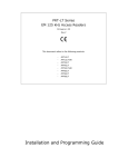
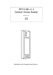
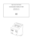
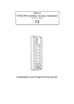
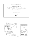
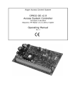
Electronic Code Lock SL2000H v1.0 Document version: Rev. C Roger Sp.j. Security Lock SL2000H v1.0 EN Rev.C.doc 2011-11-16 Features Door Lock output to control door locking device Status output to signal current working mode: Armed or Disarmed Alarm output to indicate Door Bell and Door Alarm Door Contact input for detection of door status Exit Button input to unlock the door from the external button INSTALLER code for programming MASTER code switch between armed and disarmed modes USER codes for door unlocking Programmable length of codes User indexing for easy administration of the codes Nonvolatile memory Metal enclosure, outdoor operation Three LEDs and buzzer Tamper 12VDC supply CE Introduction The SL2000H electronic code lock is dedicated to operate as a stand-alone door access control unit. It is equipped with one relay output, two transistor outputs and three inputs. All codes and parameters programmed to device are stored in nonvolatile memory. SL2000H have metal cover and outdoor operation available. Functional Description Note: The C1,C2…C10 parameters which appear in this manual refer to the configuration parameters programmed to the SL2000 during Memory Reset procedure (for details see section: Configuring the SL2000 later in this document). Outputs SL2000H has one relay output (REL1) and two transistor outputs (OUT1 and OUT2). The REL1 and OUT1 outputs can be configured to operate in one of two modes: Door Lock or Status. The OUT2 has fixed function and is always assigned to signal Door Bell and Door Alarm states. The REL1 output offers one switched NO/NC contact rated 1.5A/30V AC/DC. The OUT1 and OUT2 lines are open collector transistor lines which normally remain in high resistance state however when triggered they short to supply minus. The OUT1/2 transistor output can sink up to 50mA DC while maximum voltage applied to it must be 15V or less. Both transistor outputs are internally protected against overload. By default, in factory new device the REL1 is configured to work in the Door Lock (momentary) mode while OUT1 works in Status (latch) mode. This settings can be changed whenever required using JP3, JP4, JP5 and JP6 jumpers (for details see diagrams in section: Installation later in this document). The actual state of REL1 output is signaled on LED OPEN (green) which lights up as long as REL1 output is active. The OUT1 line is signaled on dual color LED STATUS which lights up in red when output is OFF and green when it is ON. Page 2 of 11 Security Lock SL2000H v1.0 EN Rev.C.doc 2011-11-16 Door Lock Mode (Momentary) This mode is dedicated to control some device or state which requires momentary type of control signal, usually it is used to control a door locking device (e.g. door strike or magnetic lock). Each time the valid USER code is entered the SL2000 first starts counting time delay specified by C1C2 parameters and then when it passes by output switches to active (ON) state for time defined by C3C4 parameters. Once the C3C4 time is elapsed output returns automatically to normal (OFF) state. This kind of operation is often called monostable or momentary mode. Either REL1 or OUT1 can be configured for this kind of operation. Status Mode (Latch) This mode is dedicated to control some device or system which requires bistable (latch) control, usually it can be used to control arming mode of the alarm zone or entire alarm system. When the SL2000 is in Armed mode this output remains not active, it become active when lock works in Disarmed mode. The Status Output can be physically assigned to either Relay or OUT1 physical output (for details see: JP3, JP4, JP5 and JP6 settings). The Status output can be used for rearming of an alarm zone or to control any other device or system which requires the ON/OFF method of control. This kind of operation is often called bistable or latch mode. Either REL1 or OUT1 can be configured for this kind of operation. OUT2 Output This output has fixed function and is assigned to signal two states: Door Bell Door Alarm Both states are signaled on the same output line however signalization is done using various methods of output signal modulation. For the Door Bell SL2000 uses continues (steady) signal while for the Door Alarm it uses modulated (pulsed) signal. Usually, the OUT2 line is used to trigger some kind of warning device (siren or buzzer). Door Bell In order to trigger Door Bell signalization press [#] key and keep it pressed as long as you want the door bell signal to be active. Along with signalization of the Door Bell on the output SL2000 activates its internal buzzer. Door Bell indication disappears automatically after 1-2 seconds from the moment when [#] key is released. Page 3 of 11 Security Lock SL2000H v1.0 EN Rev.C.doc 2011-11-16 Door Alarm The Door Alarm will occur when: door has been opened without entering of a valid USER code door has been opened without pressing of the Exit Button door has not been closed within designated time defined by the C5C6 configuration settings Once started the Door Alarm is indicated by the pulsed signal on OUT2 output which is accompanied by a the continues acoustic sound generated by the internal buzzer. Pressing any key will cease the acoustic signal – however this does not cancel the alarm indication on the OUT2 output. The alarm indication on this output disappears when door becomes closed or automatically after 60 seconds from the moment when alarm arose. Note: The Door Alarm has higher priority than Door Bell. When two of these events occur simultaneously SL2000 indicates Door Alarm only because it has higher priority then Door Bell indication. Inputs Input IN1: Exit Button Triggering of this input activates Door Lock (momentary) output on the same rules as entry of the valid USER code. The Exit Button is a NO type input – it becomes triggered when shorted to supply minus (GND). Input IN2: Door Contact This input is dedicated for the connection of a door open sensor. When input is open or left unconnected the code lock assumes that door is closed, when input is shorted to supply minus (GND) the SL2000 assumes that door is open. Note: If you are not going to use a door open sensor leave the Door Contact input unconnected. Without a door open sensor the SL2000 will not signal the Door Alarm. Input SYS: LED SYSTEM This input is dedicated to control the LED SYSTEM (yellow), shorting this input with supply minus lights up LED SYSTEM. The LED SYSTEM can be use to any arbitrary selected purpose required by the installer (e.g. to indicate actual status of the alarm system or any other state). Special options Option 1: Timed Lock-Out If this option is enabled the Sl2000 disables the keypad for 60 seconds after three attempts of entry of the incorrect code. After this time the SL2000 re-enables the keypad and is ready to accept new keypad’s entries. The end of 60 seconds lock-out time is indicated by two series of two beeps (** **). Option 2: Disable USER Codes When in Armed Mode If this option is enabled the SL2000 grants access only when it operates in Disarmed mode. With this option active the access to the controlled door will be totally disabled unless the SL2000 will be switched to Disarmed mode again. Thanks to this formula the MASTER user can disable access to the room by switching the unit to the Armed mode and vice verso, he can re-enable access to the controlled door by switching the lock to the Disarmed mode. The SL2000 can be switched between Armed and Disarmed modes via the MASTER code only. Page 4 of 11 Security Lock SL2000H v1.0 EN Rev.C.doc 2011-11-16 Arming and Disarming In normal operation the SL2000 may work either in the Armed or Disarmed mode. The which lights up in actual status of the lock is presented on a dual color LED STATUS red when lock is Armed and green when Disarmed. Also, the actual operating mode of the lock is indicated on the Status (latch) output line which when active indicates that unit is Disarmed. Switching lock between Armed and Disarmed modes can be carried out by MASTER code only. Whenever code lock switches to Disarmed mode is generates two series of two beeps (** **) whereas when switches to Armed mode it generates two beeps (**) only. Codes The SL2000 offers three types of codes: MASTER Code INSTALLER Code USER Codes Each type of code is dedicated for individual purpose. The length of each code can be programmed during Memory Reset procedure. The entry of each code must be followed by the [#] key which is used to mark the end of the code. MASTER Code The MASTER code is used to switch the SL2000 between Armed and Disarmed modes, it can be 4-10 digits long. INSTALLER Code The INSTALLER code is required to enter the Installer Programming mode, it can be 4-10 digits long. USER Codes These codes are used solely to trigger the Door Lock (momentary) output. Each time a valid USER code is entered the SL2000 starts counting C1C2 time delay and then activates Door Lock output for time defined by the C3C4 parameters. The USER codes can be 2-8 digits long. Note: The SL2000 enables programming of maximum 55 USER codes, each of them can be used to trigger Door Lock output. Commands Commands can be entered during normal working time of a SL2000 and doesn’t require entry to the programming mode. [USER Code] [#] Whenever a valid USER code is entered the code lock generates two beeps (**) and then starts count C1C2 time delay. After it passes SL2000 activates Door Lock (momentary) output for the time defined by C3C4 settings. [MASTER Code] [#] Each time the MASTER code is entered the SL2000 changes its arming mode (switches from Armed to Disarmed mode or in reverse direction). [INSTALLER Code] [#] After this command code lock generates two beeps (**) and enters the Installer Programming mode. In this mode installer can manage (add, modify or delete) the USER codes. Page 5 of 11 Security Lock SL2000H v1.0 EN Rev.C.doc 2011-11-16 [*][Old INSTALLER Code][#][New INSTALLER Code] [#] This command erases the current INSTALLER code and program a new one. If command is successfully accomplished the unit generates three series of two beeps (** ** **) [*] [Old MASTER Code] [#][Old MASTER Code] [#] This command erases the current MASTER code and program a new one. If command is successfully accomplished the unit generates three series of two beeps (** ** **). Note: Whenever you re-program MASTER or INSTALLER code remember that new code programmed into a unit must have the same length as the old one. [#] Normally pressing [#] is used to mark the end of the code but when pressed separately for a time longer the 0.5s it triggers Door Bell indication. Programming The USER Codes The SL2000 enables programming of up to 55 different USER codes. The USER codes can be managed (added/deleted/changed) only in the Installer Programming mode (to enter Installer Programming mode press: [INSTALLER Code]+[#]). Once in the Installer Programming mode you have following commands: [0] [1] [0] [2] … etc. … etc. … etc. [5] [5] [0] [0] [9] [9] [#] [#] [code] [# ] [#] [code] [#] ; Programming of the USER code no. 1 ; Programming of the USER code no. 2 [#] [code] [#] [#] [#][code][#] ; ; ; ; Programming of the USER code no. 55 Delete all USER codes Deletes the code entered in square brackets Exit from the Installer Programming mode When the SL2000 accepts the new USER code it generates two series of two beeps (** **). Any attempt to program the USER code which already exists in the memory or to program it with a wrong length then will cause the programming error signaled by a long acoustic beep. Configuring the SL2000 — Memory Reset In order to configure the SL2000 you must perform the Memory Reset procedure and then enroll sequentially 10 digits (C1,C2..C10) which will configure the unit for the individual installation. After the Memory Reset the entire code lock memory is erased (including all codes) and initialized with default (factory) settings. In order to perform Memory Reset do the following steps: Turn off the power supply Put the jumper on JP1 contacts Turn on the power supply Wait till the moment when SL2000 will generate three series of two beeps (** ** **) - this signal indicates that unit has erased memory and restored default configuration parameters Remove jumper from JP1 contacts Meaning of the configuration parameters: C1-C10 C1C2: Specifies the time delay from a moment when USER code is entered till moment when Door Lock output will be triggered. It can be programmed from 00 to 99s (default: 04). Page 6 of 11 Security Lock SL2000H v1.0 EN Rev.C.doc 2011-11-16 C3C4: Specifies the time for which Door Lock output will be activated. It can be programmed from 02 to 99s (default: 04). C5C6: Specifies the time within door must be closed otherwise Door Alarm will occur. The C5C6 time is started from the moment when C4C4 time has passed by. It can be programmed from 00 to 99s, the 00 value sets unlimited time for door closing (default: 09). C7: Enables or disables of reprogramming of the MASTER and INSTALLER codes, enter 03 (default: 0). C7 Reprogramming of the MASTER code Reprogramming of the INSTALLER code 0 Enabled Enabled 1 Disabled Enabled 2 Enabled Disabled 3 Disabled Disabled Note: If reprogramming of a given code is disabled the SL2000 allows you for a single attempt only to program of the given code. Once the code is programmed, you will not be able to change it unless the Memory Reset is carried out. Use this function to disable the end user to change your MASTER and INSTALLER code. C8: Enabling and disabling Option 1 and Option 2, enter 0-3 (default:0). C8 Option 1 Option 2 0 Disabled Disabled 1 Enabled Disabled 2 Disabled Enabled 3 Enabled Enabled C9: Defines the length of the USER codes, enter 0-3, (default: 1). 0 1 2 3 : : : : USER USER USER USER codes codes codes codes are are are are 2 4 6 8 digits digits digits digits long long long long C10: Defines the length of the MASTER and INSTALLER codes, enter 0-3, (default: 1). 0: Both codes are 4 digits long 1: 2: 3: Both codes are 6 digits long Both codes are 8 digits long Both codes are 10 digits long If an illegal operation occur during Memory Reset the device will signal an error (long beep) and will return to the beginning of the programming so you can start to enter the C1-C10 digits once again. The Memory Reset procedure automatically comes to an end when the last (C10) digit is entered. The device stores the configuration as well as all codes in a nonvolatile memory which can be reprogrammed whenever required. After the Memory Reset procedure comes to an end all codes are set to factory default values (see section below: Default Codes). Example: The following digits C1-C10 were entered during the Memory Reset procedure: [0][1][0][2][3][3][1][0][2][3]. This sequence sets the following options: Delay before Door Lock open: 01 second Door Lock open time: 02 seconds Page 7 of 11 Security Lock SL2000H v1.0 EN Rev.C.doc Time to close the door: 33 seconds Reprogramming of the MASTER code: disabled Reprogramming of the INSTALLER code: enabled Option 1 (Timed Lock-out): off Option 2 (Disable USER Codes When in Armed Mode): off USER codes length: 6 digits MASTER and INSTALLER codes length: 10 digits 2011-11-16 Default settings After the Memory Reset is accomplished Sl2000 restores following codes: MASTER Code All digits are “1” (1111…), the length of the code depends on the C10 parameter entered later during Memory Reset procedure. INSTALLER Code All digits are “2” (2222…), the length of the code depends on the C10 parameter entered later during Memory Reset procedure. USER Code no01 All digits are “3” (3333…), the length of the code depends on the C9 parameter entered later during Memory Reset procedure. All USER codes 02..55 All USER codes no 02 -55 are blank (they doesn’t exist). Installation The SL2000H code lock should be mounted near the supervised door on a vertical piece of supporting structure. The SL2000H can be installed either indoor or outdoor location. Assure that the surface beneath of the controller’s rear panel is flat and smooth. Disconnect power supply before making any electrical connections. Once installed and electrically connected, the unit has to be properly programmed. When forgotten, MASTER and INSTALLER codes can be restored to their default values and then programmed again. Please not that Memory Reset procedure requires access to the JP1 programming contact therefore assure access to the internal space of the lock even after installation. The code lock must be supplied form reliable power source, calculate the adequate wire gauge to guarantee that the voltage on the SL2000 DC input will be 11.5V minimum. Use separate pair of wires to supply door lock and SL2000 code lock. Always add the silicon diode (e.g. 1N4007) in parallel to the DC powered door lock, note that diode must be located as close as possible to the door lock terminals. It is forbidden to supply the door lock directly from the DC input terminals of the code lock. Do not attempt to use REL1 output for switching of voltages higher then 24V DC/AC. Page 8 of 11 Security Lock SL2000H v1.0 EN Rev.C.doc 2011-11-16 Page 9 of 11 Security Lock SL2000H v1.0 EN Rev.C.doc 2011-11-16 Connection assignments Label Description +12V Supply input plus GND Supply input minus TMP A Tamper contact A, NC max. 50mA/24V DC/AC TMP B Tamper contact B, NC max. 50mA/24V DC/AC IN1 Exit Button input, NO type IN2 Door Contact input, NO type, 1.5A/24V DC/AC SYS LED SYSTEM input, NO type OUT1 Transistor output, max. current sink 50mA/15V DC OUT2 Transistor output, max. current sink 50mA/15V DC REL1-COM REL1 output, 1.5A/24V DC/AC REL1-NO REL1-NC Technical Specification Parameter Value Supply 10...15 VDC Current consumption Avg. 25 mA @ 12V DC, Max. 80 mA @ 15V DC with relay output active Anti-sabotage protection (Tamper) NC contact, 50mA/24V Environmental Class Class IV, outdoor-general, temp.: -25°C +60°C, relative humidity: 0 - 95% Dimensions 160 X 90 X 45 mm Weight SL2000H: ~ 1300g Approvals CE Ordering Information Item Description SL2000H Vandal proof metal cover, access to the keypad protected by keylocked doors, screw connection terminals, outdoor installation available Product History Version Firmware Date Description SL2000H v1.0 N/A 06/2011 Initial release of the product Page 10 of 11 Security Lock SL2000H v1.0 EN Rev.C.doc 2011-11-16 The symbol of a crossed-through waste bin on wheels means that the product must be disposed of at a separate collection point. This also applies to the product and all accessories marked with this symbol. Products labeled as such must not be disposed of with normal household waste, but should be taken to a collection point for recycling electrical and electronic equipment. Recycling helps to reduce the consumption of raw materials, thus protecting the environment. Contact Roger sp. j. 82-400 Sztum Gosciszewo 59 Tel.: +48 55 272 01 32 Fax: +48 55 272 01 33 Technical support PSTN: +48 55 267 01 26 e-mail: [email protected] Web: www.roger.pl Page 11 of 11