1
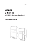
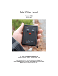
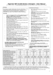
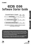
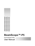
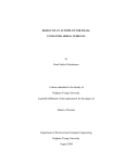
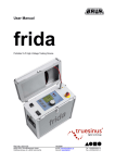
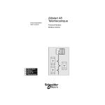
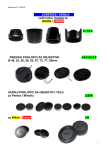
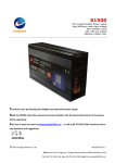
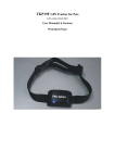
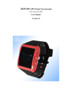
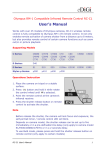
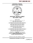
DuneCam
Users Manual
Written by
Scott Armitage
February 2009
™
Table of Contents
Table of Contents................................................................................................................ 2
Overview............................................................................................................................. 4
Aerial Controller ................................................................................................................. 6
Battery................................................................................................................................. 7
Radio ................................................................................................................................... 8
Video................................................................................................................................... 8
Aerial Controller Mounting ................................................................................................ 9
Aerial Controller Connections .......................................................................................... 11
Ground Controller............................................................................................................. 16
Using DuneCam™ ............................................................................................................. 19
Main Screen ...................................................................................................................... 19
Pan and Tilt ....................................................................................................................... 20
Shutter ............................................................................................................................... 20
Video................................................................................................................................. 20
Menu Screen ..................................................................................................................... 24
Script Menu Item .............................................................................................................. 24
Configuration File Menu Item .......................................................................................... 25
Status Screen..................................................................................................................... 26
Servo Tester ...................................................................................................................... 27
Camera Settings ................................................................................................................ 28
Troubleshooting ................................................................................................................ 29
MiniSD Card..................................................................................................................... 31
Script Files ........................................................................................................................ 32
Description of script file actions ....................................................................................... 34
Script Examples ................................................................................................................ 36
Software Update Files....................................................................................................... 38
Configuration Files ........................................................................................................... 39
Configuration File Format ................................................................................................ 39
General Settings ................................................................................................................ 43
Pan..................................................................................................................................... 44
Tilt..................................................................................................................................... 46
Shutter ............................................................................................................................... 47
Video Capture ................................................................................................................... 50
Battery / Power ................................................................................................................. 52
IR Compatibility ............................................................................................................... 53
Software History ............................................................................................................... 57
Support.............................................................................................................................. 59
Legal ................................................................................................................................. 59
Limited Warranty.............................................................................................................. 59
Overview
The DuneCam™ system allows remote control and monitoring of a camera system. It is
designed for use in aerial photography applications such as Kite Aerial Photography, Pole
Aerial Photography, or Balloon Aerial Photography, but the system can be used in other
remote camera applications as well.
The system consists of an aerial controller and a ground controller.
The aerial controller is a small circuit board that performs the following functions:
•
Control of a servo motor for pan (horizontal) movement. The pan servo can be
either a standard R/C aircraft servo or one modified for continuous rotation.
•
Control of a servo motor for tilt (vertical) movement
•
Control of a camera’s shutter by one of several mechanisms:
o A shutter servo motor that presses down on the shutter button
o IR (infrared) control for cameras controllable by an IR remote
o Hard-wired shutter switch connection
o CHDK “remote” activation for Canon cameras
•
4
Highly reliable 2-way communications with the ground controller via a 2.4 GHz
spread spectrum radio
•
Video capture from a composite video signal
•
Monitoring of the rig battery voltage
•
Highly efficient power supply functions to run all the aerial electronics
•
Positive confirmation of shutter activation
The ground controller is a handheld device with the following features:
•
Sunlight readable color LCD
•
A slider control for adjusting tilt
•
A knob control for adjusting pan
•
Buttons to control shutter, video and other functions
•
A flash memory card to configure the operation of the ground controller and the
aerial controller
•
Ability to change between up to 10 user-programmable system configurations
•
Flexible scripting feature for automated sequences of actions
•
Built-in rechargeable battery
This User’s Manual describes DuneCam™ software version 2.7.
5
Aerial Controller
The aerial controller board dimensions are 1.8” x 1.8” x 0.35” (45mm x 45mm x 9mm).
It is suggested that the board be mounted using non-conductive materials such as Velcro
or tape.
The aerial controller is shown below.
Pan Servo
Tilt Servo Shutter Servo
Shutter Switch
IR LED
Indicator LED
Video LED
Power Switch
Antenna
Battery
6
Video
Battery
The DuneCam™ aerial controller requires a battery of 6.5 V to 9.0 V. A 2-cell LithiumIon Polymer (LiPo) cell is recommended. These batteries are typically labeled as “7.2
V”, “7.4V”, “2 cell” or “2S”. Note that “9V” batteries have an initial voltage of 10 V or
more and cannot be used.
The aerial controller idles at about 50 mA, but takes more current when its radio is
transmitting, so a reasonable figure for average current is 100 mA.
In addition to this current, the aerial controller battery also supplies power to the servos.
The servo power draw is dependent on the servos chosen and the design of the rig. The
servo current will be added to the current mentioned above for the aerial controller
electronics. Keep in mind that a servo on an unbalanced rig that is constantly working to
overcome gravity may consume several times as much battery power as it would on a
balanced rig. If too much current is drawn by the servos, the servo power supply will
shut down temporarily as a precaution.
The Lithium-Ion chemistry can be damaged by discharging a 2-cell LiPo below about
5.5V. The DuneCam aerial controller will shut off the electronics when the voltage gets
lower than about 6.0V in an attempt to prevent this situation. This feature is called
under-voltage lockout (UVLO). There are two situations that could still cause trouble,
though.
•
If the battery discharges down to 5.5V, it will have very little energy left. The
very low current draw of the aerial controller when in UVLO can eventually
discharge the battery over the course of several weeks.
•
Even if disconnected from the aerial controller, a battery discharged to a low
voltage will "self-discharge" to an even lower voltage over time.
Because of this, it is recommended that LiPo's with less than 7.0V be recharged soon
after using them. If several weeks have passed since charging the batteries, they should
be charged again prior to use to get full power from the batteries. Batteries in storage
should be charged at least once per year even if not used.
Make sure the battery is charged with a charger designed for the battery type and battery
capacity that you are using. It is strongly recommended that a “balanced” charger be
used. This type of charger ensures that the two cells within the battery are charged to
equal levels. An example of this type of charger is the Cellpro 4S, 4A Cell Balancing
Charger, available from www.fmadirect.com.
Battery Safety
LiPo batteries are well suited for many remote camera applications due to their high
energy density relative to their size and weight. There are some safety precautions that
should be followed due to their high energy density.
7
•
Do not touch the positive and negative terminals of the battery to any thing other
than the connector on the aerial controller. Do not allow the aerial controller
circuit board to come in contact with anything metallic or conductive.
•
Do not carry or store the battery together with tools, metal parts or other metal
objects. Place the battery in a plastic bag when not in use.
•
Do not expose battery to water or salt water, or allow the battery to get wet.
•
Do not expose the battery to high heat, including the inside of a hot car.
See the instructions that came with your battery and battery charger for additional usage
and safety information.
Radio
The DuneCam™ system uses a 2.4 GHz Direct Sequence Spread Spectrum bi-directional
radio. This radio transmits at a level of 60 mW (18 dBm) or 100 mW EIRP power. This
power level is approved for unlicensed operation in the U.S. In other countries, it is the
operator’s responsibility to make sure that the radio complies with applicable permitted
power levels.
Video
The DuneCam™ system digitizes an analog composite video signal and sends the digital
image to the ground controller via the radio. The video has several programmable video
resolutions.
8
Aerial Controller Mounting
Mounting the aerial controller can be done in a number of ways and will depend on the
construction of the remote camera rig.
When mounting the aerial controller, take care not to let the circuit board touch metal or
conductive parts.
The aerial controller is designed to fit into a standard sized 2” x 2” plastic box (usually
sold as “potting boxes”).
Like all radios that operate in a high frequency band, it is important to mount the aerial
controller so that its antenna has an unobstructed view of the ground controller. For most
aerial camera applications, this means that the antenna of the aerial controller should be
mounted near the bottom of the camera rig.
In the following diagrams, some examples of the mounting of the aerial controller (shown
in red) are shown.
Poor placement
Radio signal will be partially block by rig
and by camera
Better placement
Less of signal is blocked
9
Best placement
None of signal is blocked
Below is an example of a KAP rig that places the antenna in a good position.
10
Aerial Controller Connections
Several connections must be made to the aerial controller. The aerial controller circuit
board is a static sensitive device and care should be taken when handling the circuit
board. Proper antistatic handling precautions include wearing cotton clothing and
discharging static electricity to ground before handling the circuitry.
Tilt
Servo
Pan
Servo
Shutter
Servo
Shutter
Switch
IR LED
(optional)
Camera video
cable
JST
Power
Lead
Video adapter
7.2V
Battery
Supplied by customer
Included with DuneCam
11
Power
Power from the battery is connected to the “JST” (or “B.E.C.”) style connector.
Power Switch
The aerial controller has a slide switch for turning on the power to the circuit. The circuit
has a low battery lockout feature where the circuit will shut off when the battery voltage
falls below 5.8 V regardless of the position of the power switch. This is done to protect
batteries from over-discharge conditions.
Pan Servo
The pan servo connection allows a standard R/C servo to be connected and this servo will
be controlled to achieve a rig panning motion. The end of the connector closest to the
edge of the circuit board should be the black (or sometimes brown) wire on the servo
lead. Either a standard servo or a servo modified for continuous rotation can be used.
For best results, use analog servos, not digital servos.
Note that the servos connections are intended for servos only, not for driving things like
video camera power.
Tilt Servo
Similarly, the tilt servo connector drives a servo for tilt motion. The tilt servo must be a
standard servo, not one modified for continuous rotation.
12
Shutter Servo
The shutter servo connector can drive a servo mechanism for pressing down a shutter
button. This connector can also be used for driving servos for other purposes through the
use of scripts.
In addition, this connector can be used to supply a +5V signal to an external system to
trigger a camera, such as for Canon cameras running CHDK. Set S_TYPE to 3 to use
this feature. The photo below shows the CHDK connections. Make sure the connections
to the camera are correct – the camera could be damaged if the signals are not connected
properly.
Ground
+5V Signal
13
Shutter Switch
The shutter switch can be configured as a single or a dual switch closure when the shutter
is activated. This can be used on some types of cameras with this arrangement for their
wired remote controls. Alternately, some cameras can be modified by bringing out wires
soldered across their internal shutter switch. The two switch connections (“primary” and
“secondary”) are non-polarized and can be connected in either direction. The two sets of
switch connections are electrically isolated from each other and from all other circuitry.
These outputs will handle up to 100 mA. Consult Dunehaven Systems for more
information about mating cabling for the shutter switch connector.
Primary switch
connection
Secondary switch
connection
Video Connection
This connection interfaces to a composite video signal from a digital camera’s video
output. Included with DuneCam™ is a short video adapter cable with a female phono
connector. This can be connected to the video cable that ships with most cameras. The
video signal can be NTSC or PAL, however, the color in the image will be better if
NTSC is used.
It may also be possible to use the video input for connecting to a small video camera.
The purchaser of the DuneCam™ system assumes all responsibility for the design and
debug of such a system.
Video LED
The green Video LED will light when the video circuit detects a video signal. This can
be helpful in debugging video connection problems.
14
IR LED
This connection can be used to control a camera’s shutter for those cameras capable of
being controlled via IR. This requires the optional IR cable. This connection is capable
of supporting most IR cameras. The mating cable is a locking cable. To remove the
connector, squeeze the sides of the connector together while gently pulling the mating
connector from the circuit board.
If using the IR LED for shutter control, the LED should be mounted so that the small
black dot on the face of the LED is pointing toward the IR window of the camera. On
some IR LED’s, there may be a round lens instead of a black dot. The LED can be
mounted a short distance from the camera, or it can attached to the camera body using
tape or Velcro.
dot
Indicator LED
The red Indicator LED will normally be lit when the circuit is on and will turn off for a
short period of time when the aerial controller is busy performing a task. If the aerial
controller voltage falls below its minimum voltage, the indicator LED will flash on and
off for a short time before the aerial controller completely turns off.
15
Ground Controller
The ground controller is a small, handheld unit that provides the user interface for the
DuneCam™ system.
Sunlight Readable LCD
Right Button (Shutter)
Left Button (Video)
Pan Adjust Knob
Menu Button
Tilt Slider
16
Lanyard Attachment
DC Adapter Jack
MiniSD Slot
Charging Indicator
Power Switch
To turn the ground controller on, slide the power switch to the right.
The ground controller has an internal rechargeable battery. To charge the battery, plug a
DC adapter into the connector on the end of the unit. This adapter should supply a
regulated 5V DC + 10% at 500 mA or more. The plug should be a standard 2.1 mm type
with the center terminal positive. Always use the charger that comes with DuneCam. If
you did not receive a charger with your DuneCam system, contact Dunehaven Systems.
A red light next to the charging jack will light when the battery is charging and will turn
off when charging is complete. The ground controller typically lasts 5 hours on a charge
with the LCD backlight on 50% of the time.
When holding the ground controller, avoid covering the radio antenna with your hand or
other objects. The radio antenna is located inside the ground controller case, to the left
side of the LCD.
17
Location of Antenna
18
Using DuneCam™
It is suggested that the aerial controller be turned on first. The red indicator LED on the
aerial controller board will flash once and then stay on. The tilt servo will move to the
center of its range. This is usually about a 45 degree angle.
Main Screen
When the DuneCam™ ground controller is turned on, the Main Screen appears.
If you have more than one Configuration File installed on your MiniSD card, the
Configuration File Selection screen will appear, asking which file you wish to use.
Each time the Main Screen is shown, the status of the aerial controller and ground
controller will be monitored and displayed on this screen. If everything is OK, you see
the “Ready” messages seen above. If a battery voltage is low or the aerial controller is
not turned on, you will see messages to that effect on this screen.
On most screens, you will see yellow text boxes at the bottom of the screen. These are
“soft key” labels for the two buttons directly below the screen. In the case of the Main
Screen shown above, pressing the left button will request a video image and pressing the
right button will activate the camera’s shutter.
On most screens, the center (“Menu”) button will either take you to the Menu Screen or
take you back to the Main Screen if you are already on the Menu Screen.
If either the ground controller or the aerial controller has a low battery, a red icon will
appear in the upper right corner. Check the Status Screen for more information about the
battery levels (see Status Screen section below).
19
Pan and Tilt
The lower portion of the ground controller has a slider for adjusting tilt and a knob for
adjusting pan. Changing these controls will immediately move the rig accordingly. The
controls are intended to be very intuitive, with the motion of the camera echoing the
motion of the slider and knob. See the section on Configuration Files for more
information on how to set up the behavior of these controls for your camera rig.
Shutter
The right button is used to tell the aerial controller to activate the shutter. Pressing the
shutter button will cause a shutter servo movement, an infrared (IR) transmission, the
closing of a shutter switch. See the section on Configuration Files for more information
on how to set up the proper type of shutter control for your camera.
Video
On the DuneCam™ system, the video consists of a sequence of one or more still images
captured via the video interface on the aerial controller. Pressing the left button at the
Main Screen will request a single frame of video and show it on the screen. The video
button can also be held down for a continuous sequence of video frames.
For best readability, the video display fills the entire screen. While the video image is
shown, the left, right, and Menu buttons still function as they did on the Main Screen.
If an error occurs during a video image (such as the aerial controller being turned off or
no video signal being detected by the aerial controller), the Main Screen will be displayed
and an error message will appear explaining what the problem is.
20
The video system shows an image of whatever your camera produces. This is normally a
live image of what the camera sees on a point-and-shoot camera. On a digital SLR, this
“live” preview is typically not available. In addition, DuneCam™ can show a “review”
image of the actual image recorded if the video image is requested immediately after a
picture is taken (see “Shutter Modes”).
21
Video Quality NEW
The video quality can be set to one of three settings to trade off video speed versus image
quality. All settings have a resolution of 120x80 pixels. The video quality is set using
the V_RESOL parameter.
22
V_RESOL
BPP
Frame
Rate
1
4
1.0 fps
2
8
0.6 fps
3
16
0.5 fps
Sample Image
Shutter Modes
Several “shutter modes” are possible. Shutter modes affect how the camera shutter
activations relate to the video.
Mode 1:
In this mode, the shutter is activated without regard to the video. No video is sent to the
ground controller after each picture is taken.
Mode 2:
Mode 2 is similar to Mode 1 but uses the video image as a means of confirming that the
shutter was activated. Most cameras LCD’s and video outputs go back for a short time
when a picture is taken. In this mode, DuneCam™ will watch the video output after the
shutter is activated. If the screen does not go black after taking a picture, it will assume
that it failed and will try the shutter again. After the video goes black, it will wait until
the video image comes back before allowing the user to take another picture. This is the
fastest way to take pictures and it allows pictures to be taken quicker than once per
second if using a fast cycle-time camera.
Mode 3:
In this mode, DuneCam™ will wait a fixed period of time after activating the shutter and
capture whatever image is on the video and will show this image on the ground
controller. The intent is that this image is the camera’s review image, letting you on the
ground see the actual image just taken by the camera. It is the user’s responsibility to
program the parameters to make the aerial controller wait the appropriate time to get the
review image.
Mode 4:
This is a combination of modes 2 and 3. DuneCam™ will activate the shutter, make sure
the video goes black, then wait until the video returns and send that image to the ground
controller. In this mode, it is not necessary to determine the exact time to wait before
capturing the video image.
If using shutter modes 1 or 2, make sure your camera’s review image is turned off.
If using a digital SLR, modes 1 or 3 may work best.
If you hear two low pitched beeps and see a red square at the bottom of the screen after
pressing the Shutter button in modes 2, 3, or 4, it may be that the camera has taken the
picture but the video signal is not present.
23
Menu Screen
Pressing the Menu button will show the Menu Screen.
On this screen, one of several items can be selected. To select a menu item, use the left
and right buttons to scroll through the list of menu items and select the desired item. The
currently selected item is highlighted in blue. Note that the soft key labels remind you
which button does what function. Scrolling past the bottom of any list brings you back to
the top of the list.
Script Menu Item
The first menu item is for entering Script Mode.
Scripts are text files that can be placed on the MiniSD card. These files describe a
sequence of servo motions and times. This can be used to smoothly move a video camera
through a series of pans and tilts much more smoothly than a person could do it using the
slider and knob controls.
In addition, if the shutter servo channel is used for another motion axis, such as a
horizontal / vertical orientation adjust, a script file can be used to move that servo.
24
Finally, script files can be used to describe a sequence of pans, tilts and shutter actions to
make the aerial controller take a panorama sequence that can be later stitched together
with software.
See the section on Script Files for more information on making and using scripts.
A list of all script files will be shown when the user selects the Script menu item. For
each script file, the contents of the first line in the file (usually a descriptive comment)
will be shown, along with the script file number.
To run a script, scroll to the desired script and select it. The script will start running and
the status will be shown on the screen. The currently executing line will be shown at the
top. A green progress bar indicates what portion of the script lines has been completed.
To skip ahead or to cancel a script, press and hold the right “Cancel” button.
Configuration File Menu Item
Another menu item selects the Configuration File. DuneCam™ uses a Configuration File
located on the MiniSD card to program various settings. See the Configuration File
section for a detailed description of how to use this file.
In the Configuration File screen, one of up to 10 configuration files can be selected. If
more than one file is found on the MiniSD card, the desired file can be selected. For each
file in the list, the configuration file number and a short description of that file are shown.
25
At that point, DuneCam™ will begin using the settings contained within the selected
configuration file. Multiple configuration files let you change the settings to support
different rigs, different cameras, or different operation preferences. The selected file can
be changed at any time while the system is running and the changes will take place
immediately.
Configuration files are a convenient way to quickly reconfigure the system in the field for
another camera, another rig, different video modes, different tilt ranges, etc.
Status Screen
The DuneCam™ Status Screen is another item on the menu. This screen shows
information about the system, such as the software versions of the aerial and ground
controllers and battery voltages of the aerial and ground controllers. It also shows the
elapsed time and the number of pictures taken since the ground controller was turned on.
26
Servo Tester
The Servo Tester is a screen that can be used to assist in programming settings into the
Configuration File. DuneCam™ expects the user to tell the system, via a Configuration
File, how to move the servos for Left, Right, Up and Down movements. Rather than
determine these settings with a trial-and-error process, this screen can be used to quickly
determine the settings.
Each servo movement parameter is expressed as a “pulse width”. The pulse width is
what makes the servo turn to a particular angle. Changing the slider and the knob in this
screen will immediately command one of the servos to go to the angle specified by a
particular pulse width.
For ease of use in setting an exact pulse width, the tilt slider is used as a “coarse”
adjustment and the pan knob is used as a “fine” adjustment. As both controls are
adjusted, the “Pulse Width =” readout will show the pulse width and the servo connected
to the aerial controller will change to this same pulse width. This pulse width will be sent
to whichever servo has a check mark next to it. Pressing the left button will change
which servo is changed when the pulse width is adjusted.
As an example, if you would like to determine the correct pulse width for the maximum
Up position for tilt, press the left button until the check mark is next to “Tilt Servo”.
Now adjust the slider and the knob. Watch the rig until it moves to the desired maximum
Up position. Note the Pulse Width value shown on the screen. This value would be used
for the corresponding setting in the Configuration File (in this case, the T_UPLPW
parameter).
Another feature of this screen is the green number shown above the pulse width after
“CAL:”. This is used for pan knob calibration. If you are using a continuous rotation
pan servo and would like to use the Pan Dead Zone feature for preventing servo creep,
turn the pan knob until it is positioned in the center of its range. You will feel a detent
(or “click”) when the knob is in this position. Note the green number and use this as the
Pan Calibration value (parameter P_CALIB).
27
Camera Settings
For best performance, a few camera settings can be made to make sure the system works
as expected.
Auto Power Down
Most cameras will shut themselves off after a period of time if no buttons on the camera
are pressed. This shut down feature should be disabled or the time lengthened as much as
possible.
Display Power Down
Some cameras will shut off the display if no buttons are pressed for a period of time.
This is different from the Auto Power Down mentioned above. The display power down
should be disabled or the time lengthened as much as possible.
Video Output
Some cameras have a menu setting that enables and disables the video output signal used
by the aerial controller. Make sure it is enabled.
Review Image
Most cameras can be set up to display a review image for a short period of time after each
picture is taken. Depending on the shutter mode you have selected, you will either want
the camera to show the review image or you will want to turn this camera feature off to
improve the speed of the camera (see “Video Options”).
Infrared Remote
Most cameras that accept an IR shutter trigger must have this feature turned on via a
menu setting. In addition, some cameras also have an adjustment for the delay between
the IR signal and the shutter activation. Make this delay as short as possible.
28
Troubleshooting
General
Issue
What to try
The rig does not respond to ground
controller actions
Examine the red LED on the aerial
controller. It should be on and turn off
briefly with each action.
The text on the screen is “- - -“
The MiniSD card is missing or is missing
the language file.
Servos
Issue
What to try
The servos work at first but after a while
they become erratic.
The servo power supply may be shutting
down due to excessive current. Make sure
that your pan and tilt axes are properly
balanced.
Video
Issue
What to try
Main Screen shows “No video signal” and
green LED on aerial controller is off
Check camera power
Check video cable connections
Check that video is enabled in camera by
connecting to a TV
Video stops working (“No video signal”)
but starts working when shutter is released
Lengthen camera’s display shut down
setting
Image sent after shutter release is black
Change from shutter mode 3 to shutter
mode 4 or lengthen V_SHDLY.
Image after shutter release appears like
normal video (not the review image)
Change from shutter mode 3 to shutter
mode 4 or shorten V_SHDLY.
Image after shutter release is intermittent
(sometimes black, sometimes not the
review image)
Change from shutter mode 3 to shutter
mode 4 or lengthen V_SHDLY and
lengthen camera’s review image time.
Video image has no color
Change the camera’s video output setting to
“NTSC”
29
Shutter
Issue
IR shutter does not trigger camera
Shutter does not trigger or only triggers
some of the time
What to try
Make sure IR control is enabled in the
camera
Makes sure IR LED is firing by looking at
the LED during a shutter release with a
digital camera.
Make sure the S_TYPE parameter is set to
the correct type of IR format.
Make sure IR LED is positioned in front of
the camera’s IR sensor window.
If using a direct-wired or servo shutter
activation, make sure the shutter is pressed
down long enough to trigger the camera.
Some cameras will not accept another
shutter press until the image has been
stored to the flash card and the review
image is no longer displayed. Unplug the
camera’s video cable and note the timing of
what happens on the LCD when the shutter
is released. Adjust the timing parameters
accordingly.
Some camera’s IR sensor can be blinded by
direct sunlight. Place back tape over the
back of the IR LED to shield the sun.
Shutter action takes too much time
If using shutter mode 1, try using mode 2.
If video review image is not needed,
consider using modes 1 or 2 instead of
modes 3 or 4. Also turn off review image
in camera.
Many newer cameras have faster shutter
cycle times.
Ground controller indicates that shutter
action failed, but camera took a picture
This can happen if using shutter modes 2, 3
or 4 but no video is present. This can also
happen in shutter modes 2, 3 or 4 if
V_SHDLY is too short.
Camera takes two pictures for each press of This can happen if using shutter modes 2, 3
shutter button on ground controller
or 4 but no video is present. This can also
happen in shutter modes 2, 3 or 4 if
V_SHDLY is too short.
30
MiniSD Card
The ground controller has a MiniSD card reader. This lets the ground controller use
information saved on MiniSD cards. This information can be of several types:
•
Script files
•
Configuration files
•
Language files
•
Software update files
Script files, configuration files and software update files are described elsewhere in this
document. Language files contain translations of the text on the ground controller into
different languages. See the “G_LANG” configuration description.
These files can be changed by plugging the MiniSD card into any personal computer or
Pocket PC as long as it is capable of reading and writing to MiniSD cards. MiniSD cards
can also be accessed with a SD card reader after placing the MiniSD card into a SD card
adapter.
For the ground controller to use the MiniSD card, it must be formatted with the FAT16
file system. This is the default in Windows when formatting a card less than or equal to
32 MB_ For cards larger than 32 MB, select the “FAT” option when formatting the card
(as opposed to “FAT32”). Macs should not be used to format the card, since the “DOS”
format they use is FAT32, which is incompatible. Macs can be used to read and write to
a previously formatted card, however.
It is suggested that you make a copy of your MiniSD files on your computer for
safekeeping in case you need to restore these files later.
31
Script Files
The MiniSD card can optionally have one or more script files on it. A script file is a
plain text file and can be edited on a personal computer. All script files must be called
“scriptN.txt”, where the “N” is a number from 0 to 19 (i.e. “script0.txt”, “script1.txt”, etc.
up to “script19.txt”).
All script files must have a particular format. The first line is ignored and is only used
for showing a description of the script on the screen.
Each of the following lines in the file describes one or more actions. All actions on each
line will be performed as a group. When each line’s task is done, the next line will be
run. This continues until the end of the script file is reached.
Comments can be added to a script line using a ‘;’ followed by the comment. Everything
on a line after the ‘;’ is ignored when executing a script. If a comment is present on a
script line, the comment is drawn on the screen when that script line is executed.
Each line has a combination of letters and numbers. Letters indicate the type of action
and the following number indicates the amount of that action. All numbers must be
whole numbers except for the D action, which can accept decimal fractional numbers.
For example, a line containing “T30” means that a tilt should be performed to a position
30% down from the top tilt limit.
For script actions that move servos, the current Configuration File parameters for pan, tilt
and shutter pulse width are used to define the limits of the range of motion.
There is a maximum of 4000 bytes and a maximum of 75 lines in each script file.
32
Here is a complete table of all script actions:
Letter
33
Action
Minimum
Value
Maximum
Value
Notes
P
Absolute Pan
0
100
% of travel to right or left
(0 = left, 100 = right)
T
Absolute Tilt
0
100
% of tilt travel
(0 = up, 100 = down)
p
Relative Pan
-100
100
% of full travel relative to
previous pan position
t
Relative Tilt
-100
100
% of full travel relative to
previous tilt position
Q
Pan and Stop
0
100
Like ‘P’ but stops the pan
servo afterwards
S
Absolute
Shutter
0
100
% of shutter servo travel
(0 = up, 100 = down)
D
Duration
0
3600
Time in seconds for this
line’s servo motions (if any)
X
Take picture
-
-
Needs no following number
R
Relay 1 State
0
1
Sets on/off state of “primary”
shutter switch contacts
r
Relay 2 State
0
1
Sets on/off state of
“secondary” shutter switch
contacts
C
CHDK
Remote signal
1
5000
Duration to activate
“Remote” signal
Description of script file actions
P
Absolute Pan
This script action will set how far to turn the pan servo left or right. 0 refers to full left
and 100 refers to full right. This will send the pan servo to the position requested. It is
intended for pan axes with unmodified servos.
T
Absolute Tilt
This script action will set how far to turn the tilt servo up or down. 0 refers to full up and
100 refers to full down. This will send the tilt servo to the position requested.
p
Relative Pan
This script action sets how far to turn the pan servo relative to its current position. This is
expressed as a percentage of the full pan travel. Positive numbers turn right and negative
numbers turn left. This action is intended for pan axes with unmodified servos.
t
Relative Tilt
This script action sets how far to turn the tilt servo relative to its current position. This is
expressed as a percentage of the full tilt travel. Positive numbers tilt down and negative
numbers tilt up.
Q
Pan and Stop
This action is similar to the P command, except at the end of the panning, the pan servo
will be stopped. This is intended for use with modified, continuous rotation servos. The
combination of the value used in the Q action and the value used in the D action will
determine the amount of panning.
S
Absolute Shutter
This script action is similar to the absolute pan and tilt actions, except that it applies to
the shutter servo. This action will always control the shutter servo channel, even if the
shutter servo is not being used to activate the camera’s shutter. This allows the shutter
servo channel to used for some other purpose if the camera’s shutter is being controlled
by some other means.
34
D
Duration
All the above script actions (P, p, T, t, Q, S) will be done over a period of time set by the
D action. This action is expressed in seconds. This setting can be a whole number like
“D5” or a fractional number like “D0.15”. Fractional numbers can be helpful when used
with the ‘Q’ action. For the P, p, T, t and S actions, the servo channel will be slowly
changed from its previous position to its new position over this period of time. This
action can be used by itself for a time delay.
X
Take a Picture
This script action will use the shutter settings in the configuration file to take a picture.
This performs the same function as pressing the Shutter button on the ground controller.
All movements of servos are done prior to executing any X action on each script line.
R
Shutter Switch 1 State
This script action controls the primary (#1) shutter switch relay. The number 0 is used to
turn the switch off and 1 turns the switch on. This action will leave the shutter switch in
the requested state after the script is complete. This allows the shutter switch to control
some camera mode, such as a half-press of the shutter, and keep it in that position until
another script (or line in a script) changes it back.
r
Shutter Switch 2 State
This script action controls the secondary (#2) shutter switch relay. It works identically to
the R action above but affects the secondary shutter switch channel.
C
CHDK Remote Signal
This script action allows the shutter servo connector to be used to trigger an external
device. The number after the “C” will determine how long a 5V pulse is sent before
returning to 0V (expressed in milliseconds). The intended use of this feature is to provide
an interface to a Canon camera running the CHDK software (see
http://chdk.wikia.com/wiki/CHDK). The CHDK software lets scripts be run in the
camera that will monitor the camera’s USB port, looking for the kind of signal that the
“C” action produces. The CHDK software can also measure the duration of these signals
and do different things depending on that duration. Keep in mind that DuneCam has no
way of knowing what CHDK scripts your camera is running, so it is good idea to add a
delay in your DuneCam script after each time-consuming CHDK process to make
DuneCam wait for the camera. Also note that although the DuneCam’s CHDK signal is
very accurately timed, some versions of CHDK do not measure the duration of the signal
very accurately. Experiment with your system to find what works best in your situation.
35
Script Examples
Multiple actions can be combined on a single line by separating actions by a space. The
order of the actions on a line is not important. For example, the line:
P10 T50 D10 ; Pan & tilt together
, means that the aerial controller will move 10% of the total distance from center towards
the right; the tilt will move halfway down and both movements will happen
simultaneously over a 10 second period. If you want the pan to complete before the tilt
begins, change it into two lines:
P10 D10
T50 D10
; First pan
; Then tilt
These assume the use of an unmodified pan servo.
_____________________________________________________________________
The relative pan and tilt will move relative to the current pan and tilt position. For
example:
p10 t-20 D5
, will move the pan 10% of the full travel to the right and the tilt will be moved up 20%
of the full tilt travel.
_____________________________________________________________________
To take several pictures in a sequence, you could do something like this (unmodified
servo):
2x2 Pano
P40 T0 D2 X
; initial position
P60 T0 D2 X
; pan right
P60 T20 D2 X
; tilt down
P40 T20 D2 X
; pan left
This will require you to know in advance exactly where the camera should be pointed,
which may be somewhat limiting. A better approach may be to use relative motions like
this:
2x2 Pano
p-5 D2 X
; initial position
t20 D2 X
; tilt down
p10 D2 X
; pan right
t-20 D2 X
; tilt up
This script uses the current pan and tilt locations as a starting point and moves the camera
relative to that position.
36
A similar script for continuous rotation servos:
2x2 Pano
Q0 D1 X
; initial position
t20 D2 X
; tilt down
Q100 D2 X
; pan right
t-20 D2 X
; tilt up
_____________________________________________________________________
To use the “shutter” servo for another use, such as to control a horizontal/vertical axis
servo, make two scripts like these:
Vertical
S0 D2
...and…
Horizontal
S100 D2
_____________________________________________________________________
DuneCam can be used as a controller for a motion control platform. DuneCam script
action durations can be very long (up to 1 hour), so it can be used for applications like
slowly panning a camera during a time-lapse sequence as follows. For this type of
application, only unmodified pan servos can be used.
30 Minute Pan
P30 T0 D2
P70 D1800
; initial position
; slow pan to right
_____________________________________________________________________
DuneCam in combination with a Canon camera running CHDK can create very powerful
scripting capabilities. Most builds of CHDK support something called “remote” or “USB
Remote”, which merely senses the presence of a voltage on the USB port. In addition,
most CHDK builds can measure the duration of this signal. With the use of simple
scripts in DuneCam and in the camera, there are an almost unlimited number of
combinations of camera configurations and actions that can be performed. For example,
you could create a DuneCam script that would trigger the shutter, take bracketed
exposures, change the shutter speed, change the zoom, and/or change the focus, all
without touching the camera. A common application is to use one pulse duration for
activating the shutter and other pulse durations in scripts for setting other camera
functions.
Here is a framework for a CHDK script that chooses one of four actions based on the
parameter in the DuneCam “C” action. Note that more sophisticated script techniques
such as nested if-then-else and gosub’s do not work reliably in CHDK. Also, note that
for some versions of CHDK, the timing values must be relaxed to compensate for the less
accurate CHDK measurement of the signal duration.
37
@title DuneCam Script Test
rem Threshold levels:
rem Send pulses of:
10~20 / 30~40 / 50~60 / >65 ms
15 / 35
/ 55
/ 75 ms
p = get_usb_power
:Loop
do
p = 10 * get_usb_power
until p>0
if p>65 then goto "L4"
if p>45 then goto "L3"
if p>25 then goto "L2"
rem Add your own handler here for Choice 1
print "Choice #1"
goto "Loop"
:L2
print "Choice #2"
goto "Loop"
:L3
print "Choice #3"
goto "Loop"
:L4
print "Choice #4"
goto "Loop"
end
Software Update Files
Software update files may be copied to the Mini SD card in order to update the software
in the ground controller and in the aerial controller. Instructions on using these other files
are included with new software releases.
Customers not purchasing directly from Dunehaven Systems can send an email to the
Contact link at www.dunehaven.com to be placed on a list to receive updates to the
DuneCam software. Be sure to specify the serial number of your system (found on the
label of either the aerial controller or on the back of the ground controller).
38
Configuration Files
The MiniSD card must have a Configuration File on it to customize the system to make it
operate the way you like. This file is a plain text file and must be named “configN.txt”,
where “N” is a number from 0 to 9 (i.e. “config0.txt”, “config1.txt”, etc. up to
“config9.txt”). If more than one configuration file is present, a menu of all configuration
files will be presented at startup and the user can select the one they want to use by
scrolling through the list and selecting the desired file. For each configuration file, the
contents of the first line in the file (usually a descriptive comment) will be shown next to
the configuration file number (“0” for config0.txt, “1” for config1.txt, etc).
To modify the configuration file(s), just eject the card, insert it into your computer’s card
reader, make your edits to the configuration file, save the file and insert the card back into
its slot in the ground controller. Select the “Config file…” menu item. If you have more
than one configuration file, select the one you wish to use. The configuration file will be
read and its new information will be immediately put to use. There is no need to cycle
power on either the ground controller or on the aerial controller to have the changes take
effect.
Configuration File Format
The configuration file consists of a number of lines with the format:
X_YYYYY = V , where:
X is a letter referring to a subsystem,
YYYYY is one or more letters referring to a subsystem parameter to be configured and
V is a number referring to the value to set that parameter to.
In addition, any text not in this format will be ignored. This allows human-readable
comments to be freely inserted anywhere in the file. If you would like to change a
parameter setting without removing the original setting from the file, make sure that the
setting you intend to use is the first one in the file – all subsequent occurrences of the
same parameter will be ignored.
Here is an example of a portion of a configuration file:
39
S_UPLPW=1000
Shutter servo up limit
S_DNLPW=1350
S_DNLPW=1450
S_DNLPW=1100
S_DNDUR=800
worked best on the new rig
<<< this seemed too high
- too low !
Shutter servo down duration
First one is
used
Others are
ignored
In this case, the shutter down pulse width would be set to 1350. The others might have
been left in the file in case you want to keep notes of other settings that you tried.
There is one limitation to be aware of. The configuration file has a size limit of 4000
bytes. If the file is larger than that, the entire file will be ignored and all parameters will
be set to their default values.
The following table lists the programmable parameters in the DuneCam™ system. For
each parameter, there is a minimum value, a maximum value and a default value. If an
attempt is made to program the settings outside the minimum/maximum range, the
settings will be changed to the nearest value within the valid range. Any settings not
defined in the configuration file will take on the value listed under “Default”. Some
settings (such as video contrast) are rarely changed from the default and can be omitted
from the configuration file unless the default value is not acceptable.
For parameters with units of “msec”, 1000 counts = 1 second delay.
For parameters with units of “mV”, 1000 counts = 1 Volt.
40
Parameter
Meaning
Minimum
Maximum
Default
Units
G_BEEPS
Beep enable
0
1
1
G_BLTMR
Backlight timer
0
120
1
G_LANG
Language for text
0
9
0
G_INDIC
Radio link indicator
0
1
0
P_LFTPW
Pan left pulse width
500
2500
1000
usec
P_RGTPW
Pan right pulse
width
500
2500
2000
usec
P_CNTPW
Pan center pulse
width
500
2500
average of P_LFTPW
and P_RGTPW
usec
P_SLEWR
Pan slew rate
1
100
10
P_CALIB
Pan knob calibration
0
255
128
P_DEADZ
Pan dead zone
0
500
0
P_HASSW
Has Pan Switch
0
1
0
P_DURAT
Pan Duration
0
5000
100
msec
T_UPLPW
Tilt up pulse width
500
2500
1300
usec
T_DNLPW
Tilt down pulse
width
500
2500
1700
usec
T_SLEWR
Tilt slew rate
1
100
10
S_TYPE
Shutter type
1
11
4
S_MODE
Shutter mode
1
4
1
41
seconds
usec
S_UPLPW
Shutter servo up
pulse width
500
2500
1300
usec
S_DNLPW
Shutter servo down
pulse width
500
2500
1700
usec
S_DNDUR
Shutter down
duration
0
5000
500
msec
S_DNDR2
Shutter 2 down
duration
0
5000
250
msec
S_INTVL
Shutter Interval
0
300
0
sec
V_BRGHT
Video brightness
0
100
50
%
V_CONTR
Video contrast
0
100
50
%
V_SATUR
Video saturation
0
100
50
%
V_SHDLY
Video delay after
shutter
0
10000
1000
msec
V_RESOL
Video quality
1
3
2
V_INVRT
Invert video image
0
1
0
B_WARNA
Aerial low battery
level
0
9000
6400
mV
B_WARNG
Ground low battery
level
0
5000
3200
mV
The various subsystems and parameters supported by this version of software are
described in the following sections.
42
General Settings
G_BEEPS
Confirmation Beep Enable
0 = No beeps
1 = Beep to confirm an action
This setting will cause the ground controller to make a short tone after each
communication with the aerial controller. Successful actions produce a single, highpitched beep. Unsuccessful actions produce two low-pitched beeps.
G_BLTMR
Backlight Timer
This setting will determine how long the LCD backlight stays on. Pressing any button
will turn the backlight on. The backlight will turn off to save power after the number of
seconds set by this parameter. Program this setting to 0 to make the backlight stay off all
the time. When the backlight is on, the ground controller consumes approximately twice
as much power from the batteries.
G_LANG
Language for text on screen
This setting affects the text on the ground controller’s screen. The text can be shown in
one of several different languages as in the list below. To have the text appear in a
particular language, the G_LANG setting must be present on the current configuration
file and a language file must be present on the MiniSD card. This language file is a file
named “langX.str”, where the ‘X’ is the number of the language. For example, for
French, G_LANG=2 and the “lang2.str” file must be present. Other settings are as
follows:
0 = English
1 = German
2 = French
3 = Dutch
Note that error messages during the startup of the ground controller are always shown in
English.
G_INDIC
Radio Link Indicator
NEW
This setting lets the user see a real-time indication of the state of the radio link between
the aerial controller and the ground controller. If set to 1, a flashing white square in the
top left corner of the main screen indicates that the radio link is working properly. If the
connection to or from the aerial controller is lost, the square turns black.
43
Pan
P_LFTPW
Pan Left Pulse Width
The P_LFTPW parameter sets the pan servo pulse width for the “full left” position of the
pan knob. Use the Servo Tester to help set this value.
By swapping the values for P_LFTPW and P_RGTPW, the direction of the panning can
be reversed.
P_CNTPW
Pan Center Pulse Width
The P_CNTPW parameter sets the pan servo pulse width when the pan knob is in its
center position. Use the Servo Tester to help set this value.
P_RGTPW
Pan Right Pulse Width
The P_RGTPW parameter sets the pan servo pulse width for the “full right” position of
the pan knob. Use the Servo Tester to help set this value.
P_SLEWR
Pan Slew Rate
This setting controls the speed at which the pan servo moves for unmodified (noncontinuous rotation) servos. The servo control signal will be smoothly changed from its
previous state to its new state to avoid rocking the camera platform due to abrupt
movements.
Expressed as a value from 1 to 100 (1=very slow, 100=very fast). Typically set to about
5, which moves the servo 90 degrees in about 1 second. Set this parameter to 100 if
using a continuous rotation servo.
P_CALIB
Pan Knob Calibration
The center position of the pan knob circuit varies slightly from one unit to another. To
compensate for this, the pan knob can be calibrated with this parameter. The value of this
parameter is typically 128 but can be adjusted higher or lower. See the description of the
Servo Test feature to determine the proper value to use for this parameter. This
parameter needs to be adjusted properly for the Pan Dead Zone and Pan Center Pulse
Width features to work properly.
44
P_DEADZ
Pan Dead Zone
When using servos modified for continuous rotation, a common problem seen with other
systems is that the servo will slowly “creep” when the pan control is attempting to keep it
motionless. The Pan Dead Zone parameter helps to control this effect by stopping all
movement of the pan servo if the pan knob is within a “dead zone” near the center of its
range.
This parameter is expressed in the same units as the pan “pulse width” settings and it
describes the left and right dead zone ranges relative to the center position (P_CNTPW).
For example, if the P_CNTPW parameter is 1500 and the P_DEADZ parameter is 100,
the pan servo would not turn if the pan knob would otherwise attempt to send a pulse
width between 1400 and 1600. For unmodified servos or to disable this feature, delete
this parameter or set it to 0.
P_DURAT
Pan Slew Duration
When using a DuneCam with a pan switch, this parameter sets how long the pan servo
will spin when the switch is pushed to the left or right. This value is the time in
milliseconds. If the pan switch is held in the left or right position, after a short delay the
pan servo will spin continuously until the switch is released. This parameter is ignored if
P_HASSW is set to 0.
45
Tilt
T_UPLPW
Tilt Up limit pulse width
This sets the servo pulse width corresponding to the maximum upward limit (usually this
is the camera being horizontal). This would be the tilt servo pulse width when the tilt
slider is in its highest position. Use the Servo Tester to help set this value.
By swapping the values for T_UPLPW and T_DNLPW, the direction of the tilt can be
reversed.
T_DNLPW
Tilt down limit pulse width
This sets the servo pulse width corresponding to the maximum downward limit (usually
this is the camera pointing straight down). This would be the servo pulse width tilt when
the tilt slider is in its lowest position. Use the Servo Tester to help set this value.
T_SLEWR
Tilt Slew Rate
This setting controls the speed at which the tilt servo moves. The servo control signal
will be smoothly changed from its previous state to its new state to avoid rocking the
camera platform due to abrupt movements.
Expressed as a value from 1 to 100 (1=very slow, 100=very fast). Typically set to about
5, which moves the servo 90 degrees in about 1 second.
46
Shutter
S_TYPE
Shutter function type
Set this parameter for the type of shutter activation you want when the Shutter button is
pressed.
1 = uses shutter servo
2 = uses wired shutter connection(s) from DuneCam™ board to camera’s shutter switch
3 = uses shutter servo connector to drive a 5V signal to an external shutter trigger
4 = uses IR shutter control (Pentax format)
5 = uses IR shutter control (Canon Type 1 format)
6 = uses IR shutter control (Canon Type 2 format)
7 = uses IR shutter control (Nikon format)
8 = uses IR shutter control (Olympus Type 1 format)
9 = uses IR shutter control (Olympus Type 2 format)
10 = uses IR shutter control (Konica Minolta format)
11 = uses IR control (Samsung format)
See the “IR Compatibility” section for more details about the camera models supported
by each selection.
S_TYPE = 3 can be used to send a 5V signal to a Canon camera configured for remote
triggering via the CHDK scripting mode. See http://chdk.wikia.com/wiki/CHDK for
more information about CHDK.
S_MODE
Shutter mode
This parameter is set to the desired shutter mode number (for example, for shutter mode
2, set S_MODE to 2). See the description of “shutter modes” earlier in this manual.
S_UPLPW
Shutter servo up limit pulse width
This parameter sets the servo pulse width corresponding to the maximum upward limit
(This is the non-pressed position). This is used for shutter presses only if S_TYPE is set
to 1. Experiment to find what works for your rig. Make sure the position is high enough
to disengage the “half pressed” shutter position.
By swapping the values for S_UPLPW and S_DNLPW, the direction of the servo
movement can be reversed.
47
When running scripts, S_UPLPW and S_DNLPW also are used to describe the “0 %”
and “100 %” values for the “S” action, regardless of whether S_TYPE is set to 1.
S_DNLPW
Shutter servo down limit pulse width
This sets the servo pulse width corresponding to the maximum downward limit (This is
the depressed position). Valid only if S_TYPE is set to 1. Experiment to find what
works for your rig. Make sure you press through the half-pressed position into the fully
pressed position. For best results, you should let this parameter limit the travel rather
than letting the servo motor stall when it cannot press any harder.
S_DNDUR
Shutter servo down duration
Length of time that shutter button should be held down. This varies with different
cameras and may vary as a function of focus settings and flash modes. Experiment to
make sure you are covered in all situations. This parameter is ignored unless S_TYPE is
set to 1 or 2.
If S_TYPE is set to 2 (wired connection), this parameter refers to the “primary” switch
contacts.
If S_TYPE is set to 3, this parameter affects how long the 5V trigger signal is present.
S_DNDR2
Shutter secondary switch down duration
In situations where a second shutter switch is needed, this parameter is used to set the
timing of the “secondary” shutter switch. Typically, the primary switch is used for “half
press” and the secondary switch is used for “full press”. This parameter is ignored unless
S_TYPE is set to 2.
The sequence is as follows:
•
Shutter primary switch closes.
•
After (S_DNDUR – S_DNDR2) milliseconds have elapsed, shutter secondary
switch closes. Primary switch is still closed.
•
After another S_DNDR2 milliseconds, both shutter switches open.
Primary Switch Closed
Secondary Switch Closed
S_DNDR2
S_DNDUR
48
There is also a special case for only activating the secondary switch. If S_DNDUR is 0
and S_DNDR2 is not 0, the primary switch will be unchanged and only the secondary
switch will be activated.
S_INTVL
Shutter Interval
DuneCam has an intervalometer that can be programmed to take a picture periodically.
This feature can be used to automatically take pictures without operator intervention. It
can also be used with cameras that power down after a period of time, forcing them to
stay awake by activating the shutter periodically. This feature will take a picture the
desired number of seconds after the previous picture, whether the previous picture was
taken by the intervalometer by the user pressing the Shutter button on the ground
controller. This feature is disabled when running scripts. The default value of 0 turns off
the intervalometer. Any other value sets the number of seconds between automatic
shutter activations.
49
Video Capture
V_BRGHT
Video brightness
Controls the video capture brightness. Higher values = lighter.
V_CONTR
Video contrast
Controls the video contrast. Higher values = more contrast.
V_SATUR
Video Color Saturation
Controls the video color saturation. Higher values = more saturated colors.
V_SHDLY
Delay before video snapshot
S_MODE = 1: V_SHDLY is ignored.
S_MODE = 2 or 4: V_SHDLY sets the maximum length of time that the aerial controller
will wait for video to return after the shutter is pressed before giving up. This should be
slightly more than the worst case time interval you ever expect to encounter.
S_MODE = 3: V_SHDLY sets the time the aerial controller will always wait before
capturing the video image. This should be carefully adjusted to make sure the video is
captured during the review image.
V_RESOL
Video Quality
1 = lowest quality
2 = medium quality
3 = highest quality
This parameter controls the video quality and video update rate. When pressing the video
button, the video will be requested from the aerial controller using the settings defined by
this parameter. Higher settings show more detail but take more time to transmit to the
ground controller. For more information, see the “Video Quality” section earlier in this
manual. This parameter also applies to images automatically shown as the shutter review
image.
50
V_INVRT
Invert Video Image
NEW
Normally, the video image is displayed on the LCD right-side-up with respect to the
video signal coming from the camera. In some situations (such as mounting the camera
inverted) it is desirable to flip the image upside-down. Set this parameter to a 1 to invert
the image.
51
Battery / Power
B_WARNA
Aerial controller low battery warning level
The ground controller will indicate a low battery condition when the aerial controller’s
battery drops below this predefined voltage. This setting can be adjusted higher or lower
to give you more or less advance notice of a low battery.
B_WARNG
Ground controller low battery warning level
The ground controller will indicate a low battery condition when the ground controller’s
battery drops below this predefined voltage. This setting can be adjusted higher or lower
to give you more or less advance notice of a low battery.
52
IR Compatibility
DuneCam can be configured to control over 150 different types of cameras via infrared
(IR) remote control. This section lists the supported camera models and the proper
setting for the Shutter Type parameter (S_TYPE) in the config.txt file. There may be
newer cameras not yet on the list that are also supported. In addition, other IR formats
can be supported upon request.
Pentax (S_TYPE = 4)
K100D
K10D
K110D
*ist
*ist D
*ist DL
*ist DS
*ist DS2
Optio 330
Optio 430
Optio 450
Optio 550
Optio 555
Optio 750z
Optio S
Optio S4
Optio S40
Optio S4i
Optio S50
Optio S5i
Optio S5n
Optio S6
Optio S60
Optio S7
Optio A10
Optio A20
Optio SV
ZX-L
MZ6
MZ-L
Optio S10
Optio A30
Canon Type 1 (S_TYPE = 5)
Digital Rebel XT 350D
Digital Rebel Xti 400D
ELPH 370Z
ELPH Jr.
ELPH Sport
ELPH Z3
EOS ELAN 7
EOS Elan 7E
EOS ELAN 7NE
EOS Elan II
EOS Elan IIE
EOS IX
EOS Rebel T2
EOS Rebel Ti
Sure Shot 120
Sure Shot 130u
Sure Shot 130u II
Sure Shot Z115
Sure Shot Z135
Sure Shot Z155
Sure Shot Z180u
Sure Shot Z90W
53
Canon Type 2 (S_TYPE = 6)
PowerShot G1
PowerShot G2
PowerShot G3
PowerShot G5
PowerShot G6
PowerShot Pro 1
PowerShot Pro 90 IS
PowerShot Pro70
PowerShot S1 IS
PowerShot S60
PowerShot S70
Nikon (S_TYPE = 7)
Coolpix 8400
Coolpix 8800
D50
D70
D70s
D80
F55
F65
F75
N65
N75
Nuvis S
Pronea S
Lite Touch series
D40
D40x
D60
D90
Olympus Type 1 (S_TYPE = 8)
C60
C70
C730
C750
C770
C2020
C2040
C3030
C3040
C4040
C5000
C5060
C7000
C7070
C8080
D40
E1
E10
E20
E100rs
E2100
E2500
E300
E330
E400
E410
E500
E510
µ300
µ400
µ410
µ500
54
Olympus Type 2 (S_TYPE = 9)
IS-3
IS-10
IS-20
IS-30
IS-50
IS-5 Deluxe
Stylus 150QD
Stylus 140
Stylus 120QD
Stylus 105
Stylus 105QD
Stylus 100 Wide
Stylus 80 Wide
Stylus 80
Stylus Epic Zoom 80
Stylus Epic 115
Stylus Epic 170
Infinity 80 QD
Infinity 105 QD
Accura Zoom 80,
Accura Zoom 105 R
Superzoom 80 S
Superzoom 120
Superzoom 160
Superzoom 800QD
Superzoom OZ 130
Konica Minolta (S_TYPE = 10)
DiMAGE F100
DiMAGE F200
DiMAGE F300
DiMAGE A200
DiMAGE S414
DiMAGE S404
DiMAGE S304
Dynax/Maxxum 5 Date
Dynax/Maxxum 4 Date
Dynax/Maxxum 3(L) Date
Dynax/Maxxum 40
Dynax/Maxxum 50 Date
Dynax/Maxxum 60
Dynax/Maxxum 70
Riva/Freedom/Capios Zoom 20
Riva/Freedom/Capios Zoom 75W
Riva/Freedom/Capios Zoom 115 Date
Riva/Freedom/Capios Zoom 125 Date
Riva/Freedom/Capios Zoom 130
Riva/Freedom/Capios Zoom 140(A)
Riva/Freedom/Capios Zoom 150 Date
Riva/Freedom/Capios Zoom 160(A)
55
Samsung (S_TYPE = 11)
Pro-815
NV7
NV7 OPS
NV8
NV10
NV11
NV15
NV20
56
Software History
Ground Controller Software
Version 2.0 –
Unreleased version
Version 2.1 – Sep 11, 2007
Initial production release
Version 2.2 – Nov 27, 2007
Added support for German, Dutch, French, Spanish
Changed appearance of Script Run screen
Improved ability to make fine adjustments to pan and tilt
Improved handling of communications errors during video reception
Improved responsiveness of button presses
Fixed bug that did not reinitialize default parameters when changing configuration
files
Other minor cosmetic changes and bug fixes
Version 2.3 – Jan. 8, 2008
Improved support for script files edited in Unix/Linux.
Fixed bug that did not automatically exit script mode in some situations
Version 2.4 – Feb 15, 2008
Changed firmware update functions to allow larger code size
Version 2.5 – Feb 21, 2008
Added intervalometer feature
Changed maximum script action duration from 1 minute to 1 hour
Added support for pan switch
Added support for setting primary and secondary shutter switches in scripts
Added support for CHDK “USB Remote” feature for shutter button presses
Added support for CHDK “USB Remote” feature in scripts
Now allows triggering of only the secondary shutter switch
Minor cosmetic changes
57
Version 2.6 – August 11, 2008
Uses improved video compression
Added option to invert video image
Now allows comments in script lines
Displays script comments during Script Run
Added radio link indicator
Improved responsiveness of Menu button
No longer waits for video review image during scripts
Improved configuration file and script file error messages
Faster canceling of scripts
Increased maximum number of lines in a script
Fixed bug that did not properly time script durations less than 0.1 second
Fixed bug that did change video setting for review until video button pressed
Minor cosmetic changes
Version 2.7 – February 9, 2008
Increased maximum number if scripts
Improved speed of configuration and script menus
Aerial Controller Software
Version 2.0 –
Unreleased version
Version 2.1 – Sep 11, 2007
Initial production release
Version 2.2 – Nov 27, 2007
Minor bug fixes
Version 2.3 – Jan. 8, 2008
Added support for Samsung IR format
Version 2.5 – Feb 21, 2008
Added support for longer script durations
Added support for setting shutter switch in scripts
Added support for CHDK “USB Remote” feature
Version 2.6 – August 11, 2008
Implemented better video compression
58
Support
Questions regarding DuneCam can be sent via email. See the Contact link at
www.dunehaven.com. Notifications of software updates are sent to known users of
DuneCam. If you purchased your system from a distributor other than Dunehaven
Systems, you can be placed on the mailing list for software updates by email request. Be
sure you include your serial number (found on the red label on the aerial controller or the
sticker on the back of the ground controller).
Legal
The design of the DuneCam™ system is Copyright © 2006-2009 Scott Armitage. This
includes the electrical design, the circuit board layouts and all software designed for the
system. You may not reverse engineer, decompile, or disassemble any DuneCam™
software nor may you reverse engineer the DuneCam™ hardware for any reason.
Limited Warranty
The DuneCam™ system is warranted to be free from defects in materials and
workmanship for a period of one year from the date of purchase. This limited warranty
covers normal use and does not cover abuse or use not in accordance with this manual.
Under no circumstance will the seller be responsible for any incidental or consequential
damages, which may occur during the use of the product, or as a result of the product's
failure to perform. In all cases, the customer's sole remedy for a product failure is limited
to the repair or replacement of the product.
59