1
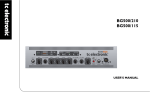
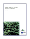
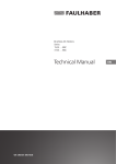
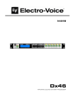
Thermal Energy
Management and Protection
Limiter Technology
1
THERMAL ENERGY MANAGEMENT AND PROTECTION LIMITER TECHNOLOGY
Version 1
Electro-Voice, Burnsville, Minnesota, USA
October 2010
© Bosch Security Systems Inc.
Thermal Energy
Management and
Protection Limiter
Technology
Rev. 1 / October 20, 2010
1. Introduction:
This application note discusses the use of the Electro-Voice Thermal Energy Management and
Protection (TEMP) Limiter. This document will cover the reasons for its development, the significant
advantages it provides in protecting loudspeaker transducers against thermal failures and how to
implement and use the TEMP Limiter in IRIS-Net project files and hardware.
2. The Need for the TEMP Limiter
Loudspeakers are designed for reliability. The design and testing process covers all components
and aims to provide the optimum performance, while simultaneously testing and analyzing the ability
to continue to function and be reliable even during extreme or abusive use. In the world of
transducer design there’s a lot that can be done to optimize thermal and mechanical parameters to
maximize output. Electro-Voice engineers work to constantly increase the peak voltage capacity and
the power handling capacity of our transducers. All components are selected and tested to work at
extreme temperatures.
Modern professional amplifier design has significantly increased the output power ratings and
instantaneous peak output capabilities to keep pace with sound reinforcement requirements. These
modern designs can present instantaneous peak voltages well above and beyond previous
generations. As a case in point, the TG7 is capable of producing 180-volt instantaneous peaks.
2
THERMAL ENERGY MANAGEMENT AND PROTECTION LIMITER TECHNOLOGY
While this provides tremendous dynamic range and power performance, instantaneous output
voltages in these extreme ranges present new challenges to operators and designers to ensure that
the loudspeakers are being driven with a safe RMS output level from the amplifier. In order to keep
the loudspeakers functioning reliably, tools must be provided to prevent against both mechanical
and thermal failures.
So, how is the user to know what RMS level they are sending to each speaker? How does the user
determine the temperature of their loudspeakers and how safely they’re driving their system? The
answer is that this is practically impossible for users to do, and that system techs should not have to
concern themselves with guesswork about voicecoil temperature. This is the reason that ElectroVoice has created the Thermal Energy Management and Protection (TEMP) limiter.
3. The TEMP Limiter in Action
The Thermal Energy and Management and Protection (or TEMP) limiter is based on a detailed
thermal model of the connected loudspeaker. It continuously calculates the temperature of the
loudspeaker voice coil as signal is applied and the speaker heats up and cools down. The thermal
model approach was selected because it proves to be more reliable and accurate than other
methods. A simple RMS voltage limiter would function, but it would neglect the fact that
loudspeakers can handle large RMS voltages for sufficiently short periods of time, so this approach
would potentially provide too much limiting. Another method would be a combined approach of
monitoring the voltage and current delivered by the amplifier. Unfortunately, this would make the
parameters depend upon how many speakers the user had paralleled on each channel and would
be limited to amplifiers with DSPs on board. The thermal model approach does not have such
limitations.
Sample by sample, the TEMP limiter tracks the voltage applied to the loudspeaker terminals and
uses this to calculate the instantaneous temperature of the voice coil. To minimize gain reduction
and maximize output, the temperature scale has been broken up into several regions. The first
temperature region is between T Ambient (ambient temperature) and TKnee (the lower threshold of the
soft knee). For a voice coil temperature in this range, no gain reduction is applied. Above TKnee gain
reduction is applied based on the RMS drive level and the voice coil temperature. The amount of
gain reduction and the rate at which it’s applied depends on the voice coil temperature. If
something goes terribly wrong, there is a TCritical (critical temperature) above which a lot of gain
reduction is applied quickly. These parameters are not user-adjustable. They are the result of
extensive simulation and testing under a variety of abusive conditions.
3
THERMAL ENERGY MANAGEMENT AND PROTECTION LIMITER TECHNOLOGY
Figure 1: An example of an abusive test with a soft knee at 120C and a critical temperature of
180C.
The TEMP limiter should not have to provide a significant amount of gain reduction under normal
operating conditions. It is designed to prevent component failures in the case where the user is
riding the fine line between pushing their system hard and pushing it to failure. The difference
between these two cases can be smaller than 1dB!
dB vs. Temperature
400
Coil Temperature (C)
350
300
250
200
150
100
50
0
20
25
30
35
40
Drive signal (dB)
Figure 2: An example of drive level vs. voice coil temperature. The difference between a coil
temperature of 250C and 200C is 1dB. This means a 1dB level reduction can prevent component
failures!
4
THERMAL ENERGY MANAGEMENT AND PROTECTION LIMITER TECHNOLOGY
4. Important Points about the Temp Limiter
The following are details and notes about the functionality of the TEMP Limiter when used in
Electro-Voice systems.
•
•
•
•
•
Bandpasses are not linked, so gain reduction can occur independently in different
pass-bands. If a system is driven very hard this can result in a change in the tonal
balance of the system. For small amounts of thermal gain reduction (<3dB) this is
not very perceptible. If there is a noticeable change in the tonal balance of the
system this can be corrected by reducing the input drive level (pre-DSP).
The TEMP limiter algorithm assumes that the amplifier is not applying its own gain
reduction. In the case where the Circuit Breaker Protection on a TG7 is set to < 30
amps, in most cases the CBP will apply gain reduction before the TEMP Limiter will,
particularly when driving a very low impedance load.
Since the TEMP limiter is temperature-based, the time constants involved are much
longer than for peak limiters. Attack and release times for the temp limiter are on the
order of seconds rather than milliseconds. This results in less audibly-noticeable
gain reduction and more transparent performance.
The TEMP limiter takes a ‘soft knee’ approach to limiting, so seeing a small amount
of gain reduction is no cause for concern. If the amount of gain reduction applied is
> 2-3dB the drive level should be decreased.
If, for some reason, power to the RCM module is lost the TEMP limiter will lose track
of the instantaneous voice coil temperature. Once the RCM module is powered up
again it will restart the temperature tracking from ambient temperature.
5
THERMAL ENERGY MANAGEMENT AND PROTECTION LIMITER TECHNOLOGY
5. Application and Use in IRIS-Net
5.1. Using the TEMP Limiter in Tour Grade Amplifiers
TEMP Limiter parameters are included in many FIR-Drive loudspeaker settings (.SPS files). These
files are available for download from the Electro-Voice website (http://www.electrovoice.com).
These files will be compatible with RCM-26 modules that are operating with V.1.15.0 firmware (or
higher) and IRIS-Net V2.4.0 (or higher). Additionally, these loudspeaker settings are included in the
Speaker Settings folder of IRIS-Net V2.4.1 (or higher).
Loudspeaker settings with TEMP Limiter parameters can be imported into devices by:
o Importing the settings into an individual amplifier
o Importing the settings into a Group of amplifiers
o Importing the settings via the IRIS-Net Project Generator
Instructions for each method are listed below.
5.1.1. Importing Loudspeaker Settings into individual Amplifiers
1. If an existing project with TG Amplifier devices is already open, proceed to step # 3. If a
new, empty project is open, begin by dragging a Tour Grade Amplifier Object from the
Object List into the Project Window.
6
THERMAL ENERGY MANAGEMENT AND PROTECTION LIMITER TECHNOLOGY
2. In the Amplifier Dialog that appears, select the number of devices, starting CAN address and
interface to be used.
3. Double-click on the amplifier object in IRIS-Net to open the Userpanel. In the Userpanel,
press the SET button in the lower right-hand corner to open the amplifier’s configuration.
7
THERMAL ENERGY MANAGEMENT AND PROTECTION LIMITER TECHNOLOGY
4. In the Amplifier Setup & Control screen, click on the DSP tab at the top of the window. This
will open a block diagram of the RCM-26’s DSP structure.
5. Below each output channel, there are buttons to import and export Speaker Settings files.
To import a Speaker Settings file with TEMP Limiter parameters, click the IMP button. This
will open a dialog which will allow navigation to the location of the file for import. The files
are available via the Electro-Voice website or are included with IRIS-Net V2.4.1. Navigate to
the location of the file to be imported, highlight the file and click Open.
8
THERMAL ENERGY MANAGEMENT AND PROTECTION LIMITER TECHNOLOGY
6. After loading a SPS file containing TEMP Limiter parameters, you will see an indication in the
Limiters block in the DSP block diagram. A green TEMP LED under the block indicates
successful loading, while a gray block indicates that the file loaded did not contain TEMP
Limiter parameters. In the example below, amplifier Channel A has loaded a .SPS file that
does not contain TEMP Limiter parameters, while Channel B has loaded a .SPS file that
does contain TEMP Limiter parameters.
9
THERMAL ENERGY MANAGEMENT AND PROTECTION LIMITER TECHNOLOGY
7. It is possible to get additional information about the behavior of both the PA Limiter and the
TEMP limiter by clicking on the Limiters Block in the DSP block diagram. This will open a
window that contains detailed information about both limiters, including whether or not
TEMP Limiters are active and loaded. Additionally, while online with IRIS-Net during
operation and dedicated gain reduction meter is provided for both the PA Limiter and the
TEMP Limiter.
10
THERMAL ENERGY MANAGEMENT AND PROTECTION LIMITER TECHNOLOGY
5.1.2. Importing Loudspeaker settings into a Group of amplifiers
1. If an existing project with Groups of TG Amplifier devices is already open, proceed to step #
2. If a new, empty project is being created, please refer to the IRIS-Net Help documentation
and Quick Start Guide for details and instructions on how to create and configure Groups.
2. To begin importing Speaker Settings into the amplifiers connected to the Groups, the
proper DSP dialog for the Group must first be selected. To do this, right-click on the Group
and select Modify properties.
11
THERMAL ENERGY MANAGEMENT AND PROTECTION LIMITER TECHNOLOGY
3. In the Group Class dialog that opens, click on the drop-down menu for the Dialog Opened
by Double-Click entry. From this menu, select “RCM26DSPUI”. The Group Class dialog
can then be closed.
4. The RCM-26 DSP dialog can now be opened by double-clicking on the Group that is to be
edited.
12
THERMAL ENERGY MANAGEMENT AND PROTECTION LIMITER TECHNOLOGY
5. The RCM-26 DSP dialog will open for the Group.
6. Below the block diagram, there are buttons to import and export Speaker Settings files. To
import a Speaker Settings File with TEMP Limiter parameters, click the IMP button. This will
open a dialog which will allow navigation to the location of the file for import. The files are
available via the Electro-Voice website or are included with IRIS-Net V2.4.1. Navigate to the
location of the file to be imported, highlight the file and click Open.
13
THERMAL ENERGY MANAGEMENT AND PROTECTION LIMITER TECHNOLOGY
7. After loading a SPS file containing TEMP Limiter parameters, you will see an indication in the
Limiters block in the DSP block diagram. A green TEMP LED under the block indicates
successful loading, while a gray block indicates that the file loaded did not contain TEMP
Limiter parameters. In the example below, a .SPS file has been loaded that does contain
TEMP Limiter parameters.
14
THERMAL ENERGY MANAGEMENT AND PROTECTION LIMITER TECHNOLOGY
8. It is possible to get additional information about the behavior of both the PA Limiter and the
TEMP limiter by clicking on the Limiters Block in the DSP block diagram. This will open a
window that contains detailed information about both limiters, including whether or not
TEMP Limiters are active and loaded. Additionally, while online with IRIS-Net during
operation and dedicated gain reduction meter is provided for both the PA Limiter and the
TEMP Limiter.
5.1.3. Importing Loudspeaker settings With the IRIS-Net Project
Generator
The IRIS-Net Project Generator is capable of creating complete IRIS-Net projects, including
devices, Groups, User Interfaces and output DSP setting based on simple user input. For additional
information on using the Project Generator, please see the IRIS-Net Project Generator Help File.
The Project Generator directly accesses the IRIS-Net Speaker Settings folder to import the DSP
settings. IRIS-Net V2.4.1 (or higher) provides Speaker Settings files that include TEMP Limiter
parameter settings, where available. Any additional Speaker Settings files that include TEMP Limiter
parameters which may be downloaded from the Electro-Voice website simply need to be placed in
the IRIS-Net Speaker Settings folder for the Project Generator to be able to access them and
import the data directly. Additionally, Speaker Settings may be imported into devices or Groups in a
project file created by the Project Generator after it is created.
15
THERMAL ENERGY MANAGEMENT AND PROTECTION LIMITER TECHNOLOGY
5.2. Using the TEMP Limiter in Dx46 Processors
TEMP Limiter parameters are included in many FIR-Drive loudspeaker settings (.SPS files). These
files are available for download from the Electro-Voice website (http://www.electrovoice.com).
These files will be compatible with Dx46 hardware that is operating with V.1.0.0 firmware (or higher)
and IRIS-Net V2.4.0 (or higher). Additionally, these loudspeaker settings are included in the
Speaker Settings folder of IRIS-Net V2.4.1 (or higher).
1. If an existing project with Dx46 devices is already open, proceed to step # 3. If a new,
empty project is open, begin by dragging a Dx46 Object from the Object List into the
Project Window.
2. Double-click on the Dx46 object in IRIS-Net to open the Userpanel. In the Userpanel, press
the DSP button in the lower right-hand corner to open the amplifier’s configuration.
16
THERMAL ENERGY MANAGEMENT AND PROTECTION LIMITER TECHNOLOGY
3. In the Dx46 Configuration panel screen, click on the DSP tab at the top of the window. This
will open a block diagram of the Dx46’s DSP structure.
9. Below each output channel, there are buttons to import and export Speaker Settings files.
To import a Speaker Settings file with TEMP Limiter parameters, click the IMP button. This
will open a dialog which will allow navigation to the location of the file for import. The files
are available via the Electro-Voice website or are included with IRIS-Net V2.4.1. Navigate to
the location of the file to be imported, highlight the file and click Open.
17
THERMAL ENERGY MANAGEMENT AND PROTECTION LIMITER TECHNOLOGY
10. After loading a SPS file containing TEMP Limiter parameters, you will see an indication in the
Limiters block in the DSP block diagram. A green TEMP LED under the block indicates
successful loading, while a gray block indicates that the file loaded did not contain TEMP
Limiter parameters. In the example below, a .SPS file has been loaded that does contain
TEMP Limiter parameters.
11. It is possible to get additional information about the behavior of both the PA Limiter and the
TEMP limiter by clicking on the Limiters Block in the DSP block diagram. This will open a
window that contains detailed information about both limiters, including whether or not
TEMP Limiters are active and loaded. Additionally, while online with IRIS-Net during
operation a dedicated gain reduction meter is provided for both the PA Limiter and the
TEMP Limiter. When configuring both the PA Limiter and TEMP limiter in this section, it is
very important to take note of the amplifier selection for each channel. This selection
provides information about the amplifier that is connected to this output that is used to
calculate certain parameters for the limiters. A selection of Electro-Voice amplifier models is
available for selection, and users are also able to enter their own information for amplifiers
not included in the list. For additional information, please refer to the Dx46 User Manual and
IRIS-Net Help File.
18
THERMAL ENERGY MANAGEMENT AND PROTECTION LIMITER TECHNOLOGY
6. Let Us help Fine Tune Your System
Let us help you get the most out of your sound reinforcement system with the highest reliability. We
can make sure that you have the best loudspeaker settings, firmware and software for the
loudspeaker, processor and amplifier combination that you are using, and the most up-to-date
support literature and software.
Contact one of the Electro-Voice Technical Support Team at one of the locations listed below.
Bosch Communications Systems
Americas
Headquarters Americas
Bosch Security Systems, Inc.
12000 Portland Ave South,
Burnsville, MN 55337, USA
Phone: 1 800 392 3497
Fax: 1 800 955 6831
Canada
Phone: 1 866 505 5551
Fax: +1 866 336 8467
Latin America
Phone: 1 952 887 5532
Fax: 1 952 736 4212
EMEA
Headquarters Europe,
Middle East & Africa
Bosch Sicherheitssysteme GmbH
Robert-Koch-Strasse 100
85521 Ottobrunn, Germany
Contact & Visitor Address
EVI Audio GmbH
Sachsenring 60
94315 Straubing, Germany
Phone: +49 9421 706 0
Fax: +49 9421 706 265
France
EVI Audio France S.A.S
Phone: +33 1 6480 0090
Fax: +33 1 6006 5103
India
Bosch Limited
Phone: +91 80 4176 8378
Fax: +91 80 4176 8263
Middle East
Robert Bosch Middle East FZE
Phone: +97 14 212 3300
Fax: +97 14 212 3388
Japan
EVI Audio Japan
Phone: +81 3 5485 4427
Fax: +81 3 5485 4428
Asia & Pacific
Thailand
Robert Bosch Limited
Phone: +662 639 3111
Fax: +662 631 2030
Headquarters APR
Robert Bosch (SEA) Pte Ltd
38 C Jalan Pemimpin
Singapore 577180
Phone: +65 6319 0616
Fax: +65 6319 0620
Australia
Bosch Security Systems Pty Ltd
Phone: +61 2 9683 4752
Fax: +61 2 9890 5928
China
Telex EVI Audio
(Shanghai) Co., Ltd.
Phone: +86 21 6317 2155
Fax: +86 21 6317 3025
19
Korea
Robert Bosch Korea
Phone: +82 31 270 4765
Fax: +82 31 270 46