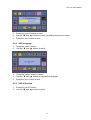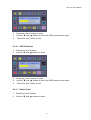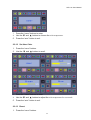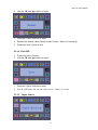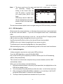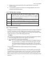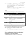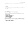
1
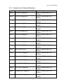
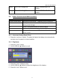
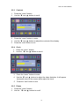
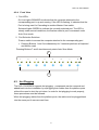
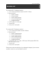
LKD-17x User Manual PACKING LIST The complete LKD-171 package consists of: 1 x 1U 19” rack mount drawer console: the LKD-171 Series Rear mounting kit ¾ 2 x short L brackets ¾ 2 x long L brackets ¾ 2 x short extending bracket ¾ 2 x long extending brackets ¾ 2 x supporting bracket 2 x PS/2 cables & 1 x VGA cable 1 x power cord 2 x Key to lock / screw pack The complete LKD-178 package consists of: 1 x 1U 19” rack mount console: the LKD-178 Series Rear mounting kit ¾ 2 x short L-shaped brackets ¾ 2 x long L-shaped brackets ¾ 2 x short extending bracket ¾ 2 x long extending brackets ¾ 2 x supporting brackets 1 x 1.8m KVM cable: 3 in 1 cable ---PS/2 mouse, PS/2 keyboard, DB15 VGA; DB25 VGA male to console. 1 x power cord 2 x Key to lock / screw pack Please check to make sure that the unit is not damaged in shipping. If you encounter a problem, contact us or your local dealer for service. Please read this manual thoroughly, and follow the installation and operation procedures carefully to prevent any damage to the LKD, and/or any of the devices that connect to it. LKD-17x User Manual SAFETY INSTRUCTIONS 1. Please read these safety instructions carefully. 2. Please keep this User’s Manual for later reference. 3. Please disconnect this equipment from power source before cleaning. Don’t use liquid or sprayed detergent for cleaning. Use moisture sheet or clothe for cleaning. 4. For pluggable equipment, the socked-outlet shall be installed near the equipment and shall be easily accessible. 5. Please keep this equipment from humidity. 6. Lay this equipment on a reliable surface when install. A drop or fall could cause user injured. 7. Do not leave this equipment in an environment unconditioned, storage temperature above 50º C, it may damage the equipment. 8. The opening on the enclosure are for air convection protecting the equipment from overheating. DO NOT COVER THE OPENING. 9. Make sure to apply proper input power voltage to the equipment. 10. Please shield the power cord in the way that people can not step on it. Do not place anything over power cord. The power cord must rated fro the voltage and current marked on the product’s electrical ratings labell. The voltage and current ratings of the cord should match the voltage and the current rating marked on the product. 11. All cautions and warnings on the equipment should be noted. 12. If the equipment is not in use for a long time, disconnect the equipment from mains to avoid being damaged by transient voltage surge. 13. Never pour liquid into ventilation openings, this could cause fire or electrical shock. 14. Never open the equipment. For safety reason, only qualified service technicians are allowed to open the equipment. 15. If one of the following situations arises, get the equipment checked by service technicians. 3 LKD-17x User Manual The Power Cord or plug is damaged. Liquid has leaked inside the equipment. The equipment has been exposed to moisture. The equipment has not worked well or you can not get it to work according to User’s Manual. The equipment has dropped and damaged. The equipment has obvious signs or breakage. 4 LKD-17x User Manual TABLE OF CONTENTS PACKING LIST .........................................................................................................................................1 SAFETY INSTRUCTIONS ........................................................................................................................3 TABLE OF CONTENTS............................................................................................................................5 CHAPTER 1 GENERAL INFORMATION ..............................................................................................8 1.1 Overview ...................................................................................................................8 1.2 Product Specification.................................................................................................8 1.3 Hardware Requirement............................................................................................ 11 1.4 Mounting the unit to your cabinet ...........................................................................12 1.4.1 Mounting the LKD into 900/850 mm cabinets............................................................13 1.4.2 Mounting the LKD into 750 mm cabinets...................................................................14 CHAPTER 2 17” TFT LCD PANEL .....................................................................................................15 2.1 Introduction.............................................................................................................15 2.1.1 Specifications.............................................................................................................15 2.1.2 Factory Preset Timing for Reference....................................................................16 2.2 Panel Controls and OSD Functions .........................................................................17 2.2.1 Auto tune (Analog Signal Only) .................................................................................17 2.2.2 Brightness ..................................................................................................................17 2.2.3 Contrast .....................................................................................................................18 2.2.4 Clock ..........................................................................................................................18 2.2.5 Phase.........................................................................................................................18 2.2.6 Horizontal Position.....................................................................................................19 2.2.7 Vertical Position .........................................................................................................19 2.2.8 OSD Language ..........................................................................................................20 2.2.9 OSD H-Position .........................................................................................................20 5 LKD-17x User Manual 2.2.10 OSD V-Position........................................................................................................21 2.2.11 Switch Color.............................................................................................................21 2.2.12 Set User Color ......................................................................................................22 2.2.13 Reset ....................................................................................................................22 2.2.14 Exit OSD ...............................................................................................................23 CHAPTER 3 INSTALLATION.................................................................................................................25 3.1 Installing the Video Card and Video Driver ...........................................................25 3.1.1 Configuring the Display Settings ...............................................................................25 3.2 Connecting the Drawer ...........................................................................................26 3.3 Turning On the Drawer...........................................................................................27 3.4 Testing the Drawer..................................................................................................28 CHAPTER 4 KVM Switch (LKD-178 SERIES only) ...........................................................................29 4.1 Features ...................................................................................................................29 4.2 Installation of LKD-178 SERIES ...........................................................................29 4.2.1 Before You Begin.......................................................................................................29 4.2.2 Single Station Installation ..........................................................................................30 4.2.3 Two Station & Three Installation................................................................................30 4.2.4 Front View..................................................................................................................31 4.3 Hot Plugging ...........................................................................................................31 4.3.1 Powering Off and Restarting......................................................................................32 4.3.2 Port Selection ............................................................................................................32 4.4 Port ID Numbering .................................................................................................33 4.4.1 Overview ....................................................................................................................33 4.4.2 Port Key In Examples: ...............................................................................................33 4.4.3 Hotkey Summary Table .............................................................................................33 4.5 OSD Operation .......................................................................................................33 4.5.1 Overview ....................................................................................................................33 6 LKD-17x User Manual 4.5.2 OSD Navigation .........................................................................................................34 4.5.3 Hotkey Navigation......................................................................................................34 4.5.4 OSD Main Menu Headings: .......................................................................................35 4.5.5 The Function Keys:....................................................................................................35 4.5.6 Factory Default Settings ............................................................................................39 4.5.7 OSD Security .............................................................................................................39 4.6 Trouble Shooting.....................................................................................................41 7 LKD-17x User Manual CHAPTER 1 1.1 GENERAL INFORMATION Overview LKD-17X is an ideal solution for network administration with multiple servers / platforms. Their 17-inch large size TFT LCD color display and ultra-low-profile compact industrial keyboard / touchpad or trackball provide the user-friendliest and most reliable environment for network administrators. All these functions are integrated in a 19-inch 1U space with rugged construction design to achieve ultra space saving and high reliability for high quality industrial/network applications. The built-in KVM switch of the LKD-178 SERIES enables easy accessibility to 8 servers / platforms and supports PS/2 keyboard, PS/2 mouse, and DB15 VGA with eight DB25 connectors. By cascading function, it can connect up to 512 computers or servers. LKD-17X monitor / keyboard drawers provide superior picture quality and state-of-the-art features mounted in an industrial grade, rack mount drawer. The drawer forms a rugged enclosure that protects the monitor from industrial hazards and permits easy access to monitor controls. LKD-17X monitors provide flicker-free color images at optimal resolutions. The monitors’ 0.264mm pixel pitch ensures crisp images with clear definition, even at high resolutions. The LKD-17X monitors are intelligent, microprocessor-based, and have an ergonomically designed display. LKD-17X monitors employ the latest in active matrix thin film transistor (TFT) technology, providing crisp screen images and wide viewing angles. Unlike CRT monitors, LCD monitors are inherently immune to the magnetic fields commonly found on the plant floor or communications centers. LCDs are also typically brighter than conventional CRT technology, making them ideal for the high ambient lighting conditions found in many of today's factory environments. On-screen menus allow for display adjustments. In addition, the monitors' Plug-n-Play+ features support Windows 95/98 and NT, while a universal power supply ensures global applicability. 1.2 Product Specification 8 LKD-17x User Manual Standard Meets EIA RS-310C 1U 19” rack mount standard Dimension (H x W x D) 43 x 443 x 548 (mm) LCD Panel 17” Active-Matrix TFT LCD Anti-reflection Glass for LCD 2 x 351 x 284 (mm) Maximum Resolution 1280 x 1024 pixels Input signal format RGB Analog Video Display control All graphic user’s interface on-screen-display control Keyboard PS/2 87-key slim keyboard with 17-key numeric keypad; or with track ball but without numeric keypad Mouse PS/2 high-quality touchpad with two mouse buttons Gross Weight 14 Kg Certification FCC class A , CE 9 10 The LKD-178 SERIES 1 2 3 4 5 6 7 8 ONLINE SELECTED MENU AUTO Caps Lock Scroll Lock AC/IN 100V~240V Num Lock SYSTEM 1 SYSTEM 2 SYSTEM 3 SYSTEM 4 SYSTEM 5 SYSTEM 6 SYSTEM 7 SYSTEM 8 POWER ON/OFF The LKD-171 SERIES MENU AUTO Scroll Lock POWER ON/OFF Caps Lock AC/IN 100V~240V Num Lock TOUCH PANEL VGA MOUSE KEYBOARD DVI LKD-17x User Manual LKD-17x User Manual 1.3 Hardware Requirement Computers Your PC must have a VGA, SVGA, or Multisync video card and video driver already installed for the monitor. If you need to install a video card or a video driver, refer to your computer documentation for instructions. Your Macintosh will require a “mac adapter” for video. Your PC-compatible computer must have a 6-pin mini-DIN (PS/2 style) mouse port Your PC-compatible computer must have a 6-pin mini-DIN (PS/2 Style) keyboard port. KVM Cables For optimum signal integrity and to simplify the layout, we strongly recommend that you use the following high quality custom cable sets: PS/2 (6 pin mini-DIN) Keyboard and Mouse, VGA (15 pin D-sub) 2L-1601P, 2L-1603P, 2L-1605P, 2L-1610P Daisy Chain LKD-178 SERIES and other KVM switches 2L-1601P, 2L-1603P, 2L-1605P, 2L-1610P 11 LKD-17x User Manual 1.4 Mounting the unit to your cabinet The unit is designed for standard 700mm ~900mm cabinets*. mounting kit in the carton. You may find the rear Please use the following combination (or more combination rather than below two) to fit in various cabinets depth. For 750mm cabinets Short L-bracket x 2 Short Extended bracket x 2 Supporting bracket x 2 For 900mm cabinets Long L-bracket x 2 Long Extended bracket x 2 Supporting bracket x 2 12 LKD-17x User Manual 1.4.1 Mounting the LKD into 900 mm cabinets 1. Fasten the supporting brackets with the chassis. 2. Fasten the extended brackets with the supporting brackets. 3. Screw the extended brackets with the system chassis. 13 LKD-17x User Manual 4. Mount the L-brackets into the guide of the extended brackets, and fasten them with the cabinet loosely. Adjust the system alignment, and fasten the screws. 5. Fasten the front screws and the rear ones. 1.4.2 Mounting the LKD into 750 mm cabinets Follow the same procedure as mounting the LKD into the 750 mm cabinet, but the extended brackets would be unnecessary. 14 LKD-17x User Manual CHAPTER 2 2.1 2.1.1 17” TFT LCD PANEL Introduction Specifications LCD Screen Type TFT LCD Display Area 337.920mm(H) × 270.336mm(V) Contrast Ratio (CR) 500:1 typical Viewing Angle Up/down: 140/160 degrees (CR=10/5) Left/right:140/160 degrees (CR=10/5) Number of pixels 1280 × 1024 Pixel pitch (H x W) 0.264mm × 0.264mm Response Time 16 msec (rising/ falling: 12/4 msec) Brightness 300cd/m2 Panel Color 262 K Back Light 4 Lamps Power Management VESA DPMS Plug & Play DDC1 & DDC2B Power Supply Power Consumption 45 watts (typical) Power saving VESA DPMS Standard, EPA/Energy Star compliant Regulations FCC class A, CE, 15 LKD-17x User Manual 2.1.2 Factory Preset Timing for Reference Type Resolution Remark Analog VESA 640*350@70Hz LKD-171 SERIES/LKD-178 SERIES Analog VESA 640*400@70Hz LKD-171 SERIES/LKD-178 SERIES Analog VESA 720*400@70Hz LKD-171 SERIES/LKD-178 SERIES Analog VESA 640*480@60Hz LKD-171 SERIES/LKD-178 SERIES Analog VESA 640*480@72Hz LKD-171 SERIES/LKD-178 SERIES Analog VESA 640*480@75Hz LKD-171 SERIES/LKD-178 SERIES Analog VESA 800*600@56Hz LKD-171 SERIES/LKD-178 SERIES Analog VESA 800*600@60Hz LKD-171 SERIES/LKD-178 SERIES Analog VESA 800*600@72Hz LKD-171 SERIES/LKD-178 SERIES Analog VESA 800*600@75Hz LKD-171 SERIES/LKD-178 SERIES Analog Mac II 35K 66.67Hz LKD-171 SERIES/LKD-178 SERIES Analog VESA 1024*768@60Hz LKD-171 SERIES/LKD-178 SERIES Analog VESA 1024*768@70Hz LKD-171 SERIES/LKD-178 SERIES Analog VESA 1024*768@75Hz LKD-171 SERIES/LKD-178 SERIES Analog MAC II-832*[email protected] LKD-171 SERIES/LKD-178 SERIES Analog VESA 1024*768@72Hz LKD-171 SERIES/LKD-178 SERIES Analog Compaq1024*768@66Hz LKD-171 SERIES/LKD-178 SERIES Analog VESA 1280*1024@60Hz LKD-171 SERIES/LKD-178 SERIES 16 LKD-17x User Manual Analog VESA 1280*1024@75Hz LKD-171 SERIES/LKD-178 SERIES Analog VESA 1280*1024@70Hz LKD-171 SERIES/LKD-178 SERIES 2.2 Panel Controls and OSD Functions Controls Description Power On/Off switch Soft power on/off button. Auto Auto-synchronize and scale down display to any valid factory preset timings. Press to scroll the function you want to adjust. Press to scroll the function you want to adjust. Menu To access the main menu. “Enter” button. 2.2.1 Adjacent LED is lit when on. This button also acts as the Auto tune (Analog Signal Only) 1. Press the “auto tune” bottom. The panel will adjust the display size automatically and also tune the panel to its best condition. 2.2.2 Brightness 1. Press the “menu” button. 2. Use the ▼ and ▲ button to scroll. 3. Press the “menu” button to enter. 4. Use the ▼ and ▲ button to adjust the brightness of the display. 5. Press the “auto” button to exit. 17 LKD-17x User Manual 2.2.3 Contrast 1. 2. Press the “menu” bottom. Use the ▼ and ▲ bottom to scroll. 3. 4. Press the “menu” bottom to enter. Use the ▼ and ▲ bottom to adjust the contrast of the display. 5. Press the “auto” button to exit. 2.2.4 Clock 1. Press the “menu” bottom. 2. Use the ▼ and ▲ bottom to scroll. 3. Press the “menu” bottom to enter. 4. Use the ▼ and ▲ bottom to adjust the video distortion. It will appear horizontal noise on the screen while adjust the clock. 5. Press the “auto” button to exit 2.2.5 Phase 1. Press the “menu” bottom. 2. Use the ▼ and ▲ bottom to scroll. 18 LKD-17x User Manual 3. 4. Press the “menu” bottom to enter Use the ▼ and ▲ bottom to adjust the video distortion. It will appear vertical 5. noise on the screen while adjust the phase. Press the “auto” button to exit. 2.2.6 Horizontal Position 1. Press the “menu” bottom. 2. Use the ▼ and ▲ bottom to scroll. 4. 5. Press the “menu” bottom to enter. Use the ▼ and ▲ bottom to move the display picture left or right. 6. Press the “auto” button to exit. 2.2.7 Vertical Position 1. Press the “menu” bottom. 2. Use the ▼ and ▲ bottom to scroll. 19 LKD-17x User Manual 3. Press the “menu” bottom to enter. 4. Use the ▼ and ▲ bottom to move the display picture up or down. 5. Press the “auto” button to exit. 2.2.8 OSD Language 1. Press the “menu” bottom. 2. Use the ▼ and ▲ bottom to scroll. 3. 4. Press the “menu” bottom to enter. Use the ▼ and ▲ bottom to choose the language 5. Press the “auto” button to exit. 2.2.9 OSD H-Position 1. Press the “menu” bottom. 2. Use the ▼ and ▲ bottom to scroll. 20 LKD-17x User Manual 3. 4. 5. Press the “menu” bottom to enter. Use the ▼ and ▲ bottom to move the OSD position left or right. Press the “auto” button to exit. 2.2.10 OSD V-Position 1. Press the “menu” bottom. 2. Use the ▼ and ▲ bottom to scroll. 3. 4. 5. Press the “menu” bottom to enter. Use the ▼ and ▲ bottom to move the OSD position up or down. Press the “auto” button to exit. 2.2.11 Switch Color 1. Press the “menu” bottom. 2. Use the ▼ and ▲ bottom to scroll. 21 LKD-17x User Manual 3. 4. Press the “menu” bottom to enter. Use the ▼ and ▲ bottom to choose the color temperature. 5. Press the “auto” button to exit. 2.2.12 Set User Color 1. Press the “menu” bottom. 2. Use the ▼ and ▲ bottom to scroll. 3. 4. Press the “menu” bottom to enter. Use the ▼ and ▲ bottom to adjust the color temperature for user mode. 5. Press the “auto” button to exit. 2.2.13 Reset 1. Press the “menu” bottom. 22 LKD-17x User Manual 2. Use the ▼ and ▲ bottom to scroll. 3. Press the “menu” bottom to enter. 4. Restore the default value (factory mode). Press ‘’ Menu’’ to executing. 5. Press the “auto” button to exit. 2.2.14 Exit OSD 1. Press the “menu” bottom. 2. Use the ▼ and ▲ bottom to scroll. 3. Press the “menu” bottom to enter. 4. Exit the OSD menu and save the values. Press ‘’ Menu’’ to execut. 2.2.15 Input Source 23 LKD-17x User Manual 24 LKD-17x User Manual CHAPTER 3 INSTALLATION 3.1 Installing the Video Card and Video Driver Before connecting the LKD-171 SERIES and LKD-178 SERIES, make sure your computer has a video card already installed for the monitor. After you connect the drawer, install the video software driver. The video driver is supplied by the video card manufacturer and may be found on the CDROM that came with your computer. If you need information on installing a video card or video driver, refer to the manual that came with your video card. 3.1.1 Configuring the Display Settings After connecting the drawer and turning on your computer, you may need to configure one or more of the following display settings: Display mode (also called desktop area or video resolution) Refresh rate (also called vertical scan rate or vertical sync) Color depth (also called color palette or number of colors) Each video card has several controls that let you adjust the display settings. However, the software and driver for each video card is unique. In most cases, you adjust these settings by using a program or utility provided by the manufacturer of the video card. Most video cards use the Windows Display Properties control panel to configure the display. To open the Windows Display Properties, click the right mouse button in a blank area of the Windows desktop and then select Properties. The Settings tab usually lets you change the Color Palette and the Desktop Area (x by y pixel resolution). Some video cards integrate additional features into the Windows Display Properties control panel to give you an exceptional setup that is flexible and easy to use. For example, the control panel may include an Advanced Properties button, an Adjustment tab, or a Refresh tab for changing other settings. Other video cards have a separate utility for setting display properties. Whenever you change the resolution, color, or refresh rate, the image size, position, or shape may change. This behavior is normal. You can readjust the image using the monitor on-screen controls. For more information on the monitor on-screen controls, refer to Chapter 2. For more information on configuring the display settings, refer to the manual that came with your video card. 25 LKD-17x User Manual 3.2 Connecting the Drawer To connect an LKD-171 SERIES and LKD-178 SERIES monitor/keyboard drawer to a computer, perform the following steps: AC/IN 100V~240V POWER ON/OFF TOUCH PANEL AC/IN 100V~240V POWER ON/OFF VGA MOUSE KEYBOARD DVI SYSTEM 8 SYSTEM 7 SYSTEM 6 SYSTEM 5 SYSTEM 4 SYSTEM 3 SYSTEM 2 SYSTEM 1 The rear view of the LKD-171 SERIES/LKD-178 SERIES 1. 2. 3. 4. 5. 6. Turn off your computer. You should always turn off your computer before connecting or disconnecting a device. Connect the KVM cable to the “System 1” connector on the monitor/keyboard drawer. Connect the video (VGA) connector of the KVM cable to the video card connector on the rear panel of your computer. Identify and connect the PS/2 mouse and PS/2 keyboard connector to the correct PS/2 ports on the rear panel of your computer. Connect the AC power cord to the power inlet on the drawer and then to a power outlet. If the LKD-171 SERIES is used, step 2 & 3 should be skipped. Users need only connect the LKD-171 SERIES VGA in port to computer system’s VGA out port. NOTE: Please refer to chapter 4 for more information about the LKD-178 SERIES. 26 LKD-17x User Manual 3.3 Turning On the Drawer Make sure all cables and the power cord are connected properly. Be sure to tighten all connector screws. Using two hands, grasp the rear of the drawer, lift the tab and pull the panel up and forward. This will disengage the momentary on/off switch and the unit should power on. The LED on the left of the monitor panel should turn from orange to green, verifying that the unit is operational. 27 LKD-17x User Manual 3.4 Testing the Drawer To test that the drawer is working properly, perform the following steps: 1. Power up the monitor/keyboard drawer, and then turn on your computer. 2. Make sure the video image is centered within the screen area. Use the OSD controls to adjust the image (see note below) or press the Auto button on the right hand side of the monitor. Note: If the unit does not power up when the panel is pulled up, try pushing the soft power on/off button on the left side of the monitor panel to power up the unit. Note: You can adjust the horizontal and vertical position, contrast, and brightness to better suit your video card and your personal preference. Refer to Chapter 2 for more information on using the on-screen menu to adjust the video display Before you begin, make sure that powers to all the devices you will be connecting up have been turned off. To prevent damage to your installation due to ground potential difference, make sure that all the devices on the installation are properly grounded. Consult your direct vendor for any technical issues if necessary. 28 LKD-17x User Manual CHAPTER 4 4.1 KVM Switch (LKD-178 SERIES only) Features Cascadable To Three Levels - Control Up to 512 Computers from a Single Console No Software Required - Computer Selection via Front Panel Switches, Hot Keys, or OSD (On Screen Display) Quick View Scan Feature for Monitoring Selected Computers PS/2 Mouse Emulation Provided For System Bootup Console's PS/2 Mouse Controls All Connected Computers PS/2 Compatible Mouse Support - Microsoft Intellimouse Explorer and Logitech FirstMouse+ Support* SVGA, VGA and Multisync Monitor Support LED Display For Easy Status Monitoring Supports High Quality CS Series Custom Connector Cables Hot Pluggable - Add or Remove Computers for Maintenance Without Powering Down the Switch Note: 1. PS/2 compatible mouse support is for three button (wheel) mice. The Logitech Mouse Ware program’s Change Device procedure does not work on Microsoft NT systems. 4.2 4.2.1 Installation of LKD-178 SERIES Before You Begin Make sure that power to all the devices you will be connecting up have been turned off. To prevent damage to your installation due to ground potential difference, make sure that all devices on the installation are properly grounded. Consult your dealer for technical details, if necessary. 29 LKD-17x User Manual 4.2.2 Single Station Installation In a Single Stage installation, there are no additional KVM switch daisy chained down from the LKD-178 SERIES. To set up a single stage installation, do the following: 1. Use connector cable sets (as described in the Hardware Requirements section), to connect any available monitor, keyboard and mouse ports of the computer you are installing. 2. Plug the adapter cable into the LKD-178 SERIES's power jack, then plug the power adapter into an AC power source. 3. Turn on the power to the computers 4.2.3 Two Station & Three Installation With the combination of KVM switch box, you can cascade up to two or three levels. For two or three stage installation, please refer to the manuals in the KVM switch box. AC/IN 90V~264V SYSTEM 8 SYSTEM 7 SYSTEM 6 SYSTEM 5 SYSTEM 4 SYSTEM 3 SYSTEM 2 SYSTEM 1 POWER ON/OFF The rear view of the LKD-178 SERIES Note: We strongly recommend you directly contact your dealer for KVM switch boxes. 30 LKD-17x User Manual 4.2.4 Front View 1. Port LEDs On Line:Lights ORANGE to indicate that the computer attached to the corresponding port is up and running. If the LED is flashing, it indicates that the Port is being used for Cascading to another Master View switch. Selected:Lights GREEN to indicate the currently selected port. The LED is steady under normal conditions, but flashes when its port is accessed under Auto Scan mode. 2. Port Selection Switches Press a switch to access the computer attached to the corresponding port Pressing Buttons 1 and 2 simultaneously for 3 seconds performs a Keyboard and Mouse reset Pressing Buttons 7 and 8 simultaneously starts Auto Scan Mode. 1 1 2 3 5 4 6 7 8 ONLINE SELECTED 2 4.3 Hot Plugging The LKD-178 SERIES supports hot plugging - components can be removed and added back into the installation by unplugging their cables from the platform ports without the need to shut the unit down. In order for hot plugging to work properly, these procedures must be followed: When hot plugging cables from the platform ports, the cable must be plugged back into the same port it was removed from. 31 LKD-17x User Manual 4.3.1 Powering Off and Restarting If it becomes necessary to Power Off one of the LKD-178 SERIES units, before starting it back up you must do the following: 1. Shut down all the computers that are attached to it. 2. Unplug the power adapter cable. 3. Wait 10 seconds, then plug the LKD-178 SERIES stations back in, starting with the last station in the chain and working back to the station you originally shut down. 4. After the LKD-178 SERIES is, power On the computers, starting with the ones attached to the last station in the chain and working back to the station you originally shut down. 4.3.2 Port Selection The LKD-178 SERIES provides three methods to obtain instant access to any computer in your installation: Manual; Hotkey; and OSD. Manual Simply press the appropriate Port Selection Switch on the LKD-178 SERIES's front panel. After you press the switch, the Selected LED lights to indicate that the port is currently selected. The OSD automatically switches to highlight the computer that you have selected. Note: Simultaneously pressing Port Selection buttons 7 and 8 on the First Stage unit initiates the Quick View Scan feature, in which all the ports that are selected for Quick View scanning are cycled through. The length of time spent on each port is determined with the OSD F6 SET function (see the OSD Operation section for details). Hot Key Navigation Hotkey navigation allows you to conveniently access any computer directly from the keyboard, instead of having to manually select it with a Port Selection switch. To select a port with the Hotkey method, do the following: 1. Press [Ctrl]+[Alt]+[Shift] to invoke the hotkey function. 2. Key in the Port ID number (see Port ID Numbering, below), then press [Enter] Note: 1. Press the keys in sequence - one key at a time. First [Ctrl], then [Alt], then [Shift]. 3. After invoking the hotkey function with the [Ctrl]+[Alt]+[Shift] combination, you must key in the Port ID and press [Enter] within 1 second for each keypress. 32 LKD-17x User Manual OSD On Screen Display (OSD), provides a menu driven interface to handle the computer switching procedure. OSD operation is discussed in detail beginning on page 15 4.4 Port ID Numbering 4.4.1 Overview Each CPU Port on a LKD-178 SERIES installation is assigned a unique Port ID. You can directly access any computer of the installation by specifying the Port ID of the CPU Port that the computer is connected to - either with the Hotkey port selection method, or from the OSD Main Menu. 4.4.2 Port Key In Examples: Access a computer attached to Port 3, key in 3 for the Port ID, as follows: [Ctrl]+[Alt]+[Shift] 3 [Enter] 4.4.3 Hotkey Summary Table This Combination: Does This: [Ctrl] + [Ctrl] Invokes the OSD (Default) [Scroll Lock] + [Scroll Lock] Invokes the OSD (Alternate Method) [Ctrl]+[Alt]+[Shift] [Port ID] [Enter] Switches access to the computer that corresponds to the Port ID number (see Port Key In Examples, above). [Ctrl]+[Alt]+[Shift] [0] [Enter] To invoke Auto Scan mode. 4.5 4.5.1 OSD Operation Overview On Screen Display (OSD), provides a menu driven interface to handle the computer switching procedure. Although Hotkey switching still works, using OSD is a great deal more convenient - especially in large, daisy chained installations where it is difficult to keep track of which port a particular computer is attached to. All operations start from the OSD Main Menu. To pop up the Main Menu, tap either Ctrl key twice. 33 LKD-17x User Manual Note: 1. The keys must be on the same side (both left, or both right) can optionally change the LIST:ALL hotkey to the Scroll Lock key PN QV PC NAME (see F6, below), in which case 2-5 ABC + 2-6 XYZ you would press [Scroll Lock] 2-7 twice. 2-8 OSD always starts in List view, with the highlight bar at the same position it was in the last time it was closed. 2. You 3 4 5-1 5-2 F1 GOTO F2 SCAN F3 LIST F4 QV F5 EDIT F6 SET The next two sections explain how to navigate using the OSD and Hotkey methods. 4.5.2 OSD Navigation [Esc] cancels the current selection, or dismisses the current menu and moves back to the menu one level above. If you are at the highest menu level, it deactivates OSD. Use the Up and Down Arrow Keys or click on the Up and Down Triangle symbols () to move up or down through the list one line at a time. Use [Pg Up] and [Pg Dn] or click on the Up and Down Arrow symbols (Ï Ð) to move up or down through the list one screen at a time To activate a port, move the Highlight Bar to it then press [Enter]. After executing any action, you automatically go back to the menu one level above. 4.5.3 Hotkey Navigation Hotkey navigation can also be used under OSD as follows: From the OSD Main Menu, press [Ctrl]+[Alt]+[Shift]. Key in the Port ID for the computer you wish to access (see Port ID Numbering, above), then press [Enter]. The console now controls the computer that you have selected, and the OSD automatically closes. When you use this method, note the following: 1. Although access switches to the port you just specified, the highlight bar on the OSD screen doesn’t move. 2. You must press [Ctrl], [Alt], [Shift] one after the other - not all at the same time. 3. After pressing the [Ctrl]+[Alt]+[Shift] combination, you must key in the Port ID and press [Enter] within 1 second for each keypress. 4. The keys must be pressed and released one key at a time. 34 LKD-17x User Manual 5. Number keys must be pressed from the regular keyboard; not from the numeric keypad. If you submit an incorrect Port ID, an error message displays, and you are returned to the OSD Main Menu. 6. 4.5.4 OSD Main Menu Headings: PN This column lists the Port ID numbers (Station Number - Port Number) for all the CPU Ports on the installation. The simplest method to access a particular computer is to move the Highlight Bar to it, then press [Enter]. QV If a port has been selected for Quick View scanning (see F2 and F4, below), an arrowhead displays in this column to indicate so. PC Lists all the computers that are Powered On and are On Line. NAME 4.5.5 If a port has been given a name (see F5, below), its name appears in this column. The Function Keys: Pressing a Function Key brings up a submenu that is used to configure and control the OSD. For example, you can: rapidly switch to any port; scan selected ports only; limit the list you wish to view; designate a port for Quick View scanning; create or edit a port name; or make OSD setting adjustments. ♦ F1 GoTo: GoTo allows you to switch directly to a port by either of the following two methods: 1. Move the Highlight Bar to the port you want then press [Enter]. 2. Key in the Port ID or Name, then press [Enter]. Note: GoTo has a special feature that narrows the list of available choices as you type the name. For example, if the first letter you type is a, the list only displays those ports whose names begin with a. If the next letter you type is b, the list only displays the ports whose names begin with ab, etc. To return to the OSD Main Menu without making a choice, press [Esc]. ♦ F2 Scan: Pressing [F2] initiates Quick View Scanning, in which the OSD cycles through all the ports that are currently selected in the List view (see F3, below), and displays each one for the amount of time set with the Set Scan Duration function (see F6, below). When you want to stop at a particular location, press the [Spacebar] to stop scanning. 35 LKD-17x User Manual Note: 1. If the scanning stops on an empty port, or one where the computer is attached but is powered Off, the monitor screen will be blank, and the mouse and keyboard will have no effect. To recover, key in the Hotkey sequence (see Hotkey Selection, above), for any Port ID that has an active computer attached. 2. As the OSD cycles through the selected ports, and appears in front of the Port ID display for each computer to indicate that the computer is being accessed under Quick View Scan Mode. ♦ F3 List: This function lets you broaden or narrow the scope of which ports the OSD lists. The choices and their meanings are given in the table, below: Choice Meaning ALL To list the Port ID numbers and Names (if names have been specified - see F5), of all the ports on the installation. QVIEW To list only the ports that has been selected for Quick View scanning (see F4, below). POWERED ON + To list only the ports that have been selected for Quick View QVIEW scanning (see F4, below), and that have their attached computers Powered On. QVIEW + NAME NAME To list only the ports that has been selected for Quick View scanning (see F4, below), and has been assigned names (see F5, below). To list only the ports that has been assigned names (see F5, below). POWERED ON To list only the ports that have the attached computers powered on. To make a choice, move the Highlight Bar to the one you want, then press [Enter]. An icon appears before the choice to indicate that it is the currently selected one. Note: 1. You can access any port on any list by using the Navigation Keys then pressing [Enter]. 2. If you select a port that does not have a computer attached to it, or if the attached computer is powered Off, the OSD will still switch to it, and will not show an error. ♦ F4 QV: QV lets you select the ports you want to include for automatic scanning under the Quick View Scanning function (see F2, above). [F4] is a toggle: if a port isn’t selected, it selects it; if a port is selected, it deselects. To select/deselect a port, move the highlight bar to it, then press [F4]. 36 LKD-17x User Manual When a port has been selected, an arrowhead displays in the QV column to indicate so. The arrowhead disappears when a port is deselected. ♦ F5 Edit: To help remember which computer is attached to a particular port, every port can be given a name. The Edit function allows you to create, modify, or delete port names. To Edit a port name: 1. Move the highlight bar to the port you want to edit. 2. Press [F5]. 3. Key in the new Port Name, or modify/delete the old one. The maximum number of characters allowed for the Port Name is 15. Legal characters include: All alpha characters: a - z; A - Z All numeric characters: 0 - 9 +, -, /, :, ., and Space Case does not matter; OSD displays the Port Name in all capitals no matter how they were keyed in. 4. When you have finished editing, press [Enter] to have the change take effect. To abort the change, press [Esc]. 37 LKD-17x User Manual F6 Set Pressing [F6] brings up an OSD configuration menu. To change a setting: 1. Move the highlight bar to the choice you want, then press [Enter]. 2. On the submenu that appears next, move the highlight bar to the choice you want and press [Enter]. ♦ An icon of a pointing finger indicates which choice is the currently selected one. An explanation of the choices is given in the table, below: Setting CHANNEL DISPLAY MODE Function To select how the Port ID is displayed: the Number plus the Name (PN + NAME); the Number alone (PN); or the Name alone (NAME). CHANNEL DISPLAY DURATION To determine how long a Port ID displays on the monitor after a CHANNEL DISPLAY POSITION To position where the Port ID appears on the screen. Use the Arrow Keys, Pg Up, Pg Dn, Home, End, and 5 (on the numeric keypad with Num Lock off), to position the Port ID display, then press [Enter] to lock the position and return to the Set submenu SCAN DURATION To determine how long the display dwells on each port as it cycles through the selected ports in Quick View Scan Mode. The available options are: 3, 5, 10, 15, 20, 30, 40, and 60 seconds. OSD ACTIVATING HOTKEY To select which Hotkey activates the OSD function: [Ctrl] [Ctrl] or [Scroll Lock] [Scroll Lock]. The default is the Ctrl key combination, but this may conflict with programs running on the computers, in which case, the Scroll Lock option should be used. SET PASSWORD To set a password in order to control access to: Locking/Unlocking the Console; Clearing the Name List; and Restoring Default Values. See OSD Security Features, below, for password setting details. port change has taken place: 3 Seconds; or Always On. CLEAR THE NAME To clear all Port Names from the Name List. You are asked to LIST* confirm before the procedure goes on. Key in Y, then press [Enter] to confirm. While the names are being cleared, a message appears on the display to indicate so. After the names have been cleared, another message appears to indicate that the procedure completed successfully RESTORE To clear all settings from memory, and returns the unit to the 38 LKD-17x User Manual Setting Function DEFAULT VALUES* factory defaults. You are asked to confirm before the procedure goes on. Key in Y, then press [Enter] to confirm. While the settings are being cleared, a message appears on the display to indicate so. After the settings have been cleared, another message appears to indicate that the procedure completed successfully. LOCK CONSOLE* To lock or unlock the Console. When the Console is locked, only the current monitor screen displays. Attempts to input information from the console have no effect; attempts to switch to a different port, either from the Console or by pressing the manual switches, have no effect either. The only way to regain access to the computers is by Unlocking the Console. If a password has been set, you must provide the password in order to Lock / Unlock the Console. If no password has been set, pressing [Enter] will Lock / Unlock the Console. * If a password has been set, these settings require you to supply a proper password in order to access them. See the OSD Security section, below, for details. 4.5.6 Factory Default Settings The factory default settings are as follows: Setting Default Display Duration Always On Display Mode The Port Number plus the Port Name Scan Duration 3 Seconds 4.5.7 OSD Security In order to prevent unauthorized access to the computers, the OSD provides a password security feature. If a password has been set, the OSD will request that the user specify it before allowing entry. To set a password: 1. Press [F6] to bring up the Setup configuration menu. 2. Move the highlight bar to Set Password, then press [Enter]. 3. Key in the new password, then press [Enter]. The password may be up to 8 characters long, and can consist of any combination of letters and numbers (A - Z, 0 - 9). 4. Key in the new password again, in order to confirm that it is correct, then press [Enter]. 39 LKD-17x User Manual If the two entries match, the new password is accepted and the screen displays the following message: SET PASSWORD OK If the entries do not match, the screen displays the message: PASSWORD NOT MATCH in which case you must start again from the beginning. Note:To modify or delete a previous password, access the Password function as in Step 1, then use the backspace or delete key to erase the individual characters. 40 LKD-17x User Manual 4.6 Trouble Shooting Symptom Erratic Behavior Possible Cause Action Unit not receiving Use the Power Adapter that was supplied enough power under with the unit to provide external power. self-powered operation. Pressing Hot Keys The connection from gets no response the selected port to the target computer has been broken, or the computer is turned OFF. Check the Online LED for the selected port. If it is not lit: Manually press one of the Select switches to connect to a computer that is powered ON. Check the cables to make sure they are all properly connected. Improper keyboard reset. Reset the keyboard (and mouse) by simultaneously pressing Buttons 1 and 2 on the First Stage unit for 3 seconds. Unplug the keyboard connector from the Console Keyboard Port, then plug it back in. Improper Master View reset. Turn off all Master View units and wait five seconds before turning them back on. Note: If the unit is operating under Self-powered mode (without the optional Power Adapter), you must unplug the power cords of any computers that have the Keyboard 'Power On' function, otherwise the switch will still receive power from the computers. Incorrectly keying in After invoking the hotkey function with the Port ID. [Ctrl]+[Alt]+[Shift] combination, be sure to key in the Port ID and press [Enter] within 1 second for each key. Mouse (TouchPad) not responding Improper mouse reset. 1. Reset the mouse (and keyboard) by simultaneously pressing Buttons 1 and 2 on the First Stage unit for 3 seconds. Unplug the mouse connector from the Console Mouse Port, then plug it back in. 2. Check the connector from mouse 41 Hawkeye User Manual module to PCBA, it’s so fragile that the soldering is easy to be broken by intensive force; PLEASE DO NOT OPEN THE UP COVER OF THE KEYBOARD WITHOUT INSTRUCTION OF ORIGINAL MAKER 42