1
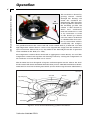
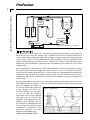
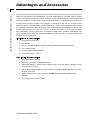
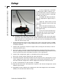
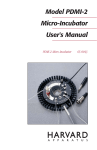
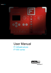
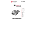
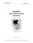
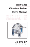
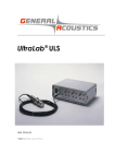
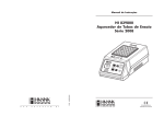
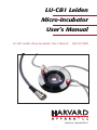
LU-CB1 Leiden
Micro-Incubator
User’s Manual
LU-CB1 Leiden Micro-Incubator User’s Manual
MA1 65-0040
Publication 5403-006-REV-B
WEEE/RoHS Compliance Statement
EU Directives WEEE and RoHS
To Our Valued Customers:
We are committed to being a good corporate citizen. As part of that commitment,
we strive to maintain an environmentally conscious manufacturing operation. The
European Union (EU) has enacted two Directives, the first on product recycling
(Waste Electrical and Electronic Equipment, WEEE) and the second limiting the use
of certain substances (Restriction on the use of Hazardous Substances, RoHS).
Over time, these Directives will be implemented in the national laws of each EU
Member State.
Once the final national regulations have been put into place, recycling will be offered
for our products which are within the scope of the WEEE Directive. Products falling
under the scope of the WEEE Directive available for sale after August 13, 2005 will
be identified with a “wheelie bin” symbol.
Two Categories of products covered by the WEEE Directive are currently exempt
from the RoHS Directive – Category 8, medical devices (with the exception of
implanted or infected products) and Category 9, monitoring and control instruments.
Most of our products fall into either Category 8 or 9 and are currently exempt from
the RoHS Directive. We will continue to monitor the application of the RoHS
Directive to its products and will comply with any changes as they apply.
• Do Not Dispose Product with Municipal Waste
• Special Collection/Disposal Required
Table of Contents
LU-CB1 Leiden Micro-Incubator User's Manual
1
SUBJECT
PAGE NO.
Warranty and Repair Information:
Serial Numbers ..................................................2
Calibrations ........................................................2
Warranty ............................................................2
Repair Facilities and Parts ................................2
Introduction:
Micro-Incubator Construction ............................3
Operation ................................................................4
Perfusion:
Fluid Perfusion ..................................................5
Gas Perfusion and Grounding:
Gas Perfusion ....................................................6
Grounding ..........................................................6
Advantages and Accessories:
Included Accessories ........................................7
Optional Accessories..........................................7
Setup ......................................................................8
Publication 5403-006-REV-B
Warranty and Repair Information
2
LU-CB1 Leiden Micro-Incubator User's Manual
Serial Numbers
All inquires concerning our product should refer to the serial number of the unit.
Serial numbers are located on the rear of the chassis.
Calibrations
All electrical apparatus is calibrated at rated voltage and frequency.
Wa rr a n t y
Harvard Apparatus warranties this instrument for a period of one year from date of
purchase.At its option, Harvard Apparatus will repair or replace the unit if it is found
to be defective as to workmanship or material.
This warranty does not extend to damage resulting from misuse, neglect or abuse, normal wear and tear, or accident.
This warranty extends only to the original customer purchaser.
IN NO EVENT SHALL HARVARD APPARATUS BE LIABLE FOR INCIDENTAL OR
CONSEQUENTIAL DAMAGES. Some states do not allow exclusion or limitation of
incidental or consequential damages so the above limitation or exclusion may not
apply to you. THERE ARE NO IMPLIED WARRANTIES OF MERCHANTABILITY,
OR FITNESS FOR A PARTICULAR USE, OR OF ANY OTHER NATURE. Some states
do not allow this limitation on an implied warranty, so the above limitation may not
apply to you.
If a defect arises within the one-year warranty period, promptly contact Harvard
Apparatus, Inc. 84 October Hill Road, Building 7, Holliston, Massachusetts
01746-1371 using our toll free number 1-800-272-2775. Goods will not be accepted
for return unless an RMA (returned materials authorization) number has been issued
by our customer service department. The customer is responsible for shipping
charges. Please allow a reasonable period of time for completion of repairs,
replacement and return. If the unit is replaced, the replacement unit is covered only
for the remainder of the original warranty period dating from the purchase of the original device.
This warranty gives you specific rights, and you may also have other rights which vary
from state to state.
Repair Facilities and Part s
Harvard Apparatus stocks replacement and repair parts. When ordering, please
describe parts as completely as possible, preferably using our part numbers. If practical, enclose a sample or drawing.We offer a complete reconditioning service.
CAUTION
This apparatus is not registered with the FDA and is not for clinical use on
human patients.
CAUTION: Not for clinical use on human patients.
Publication 5403-006-REV-B
Introduction
LU-CB1 Leiden Micro-Incubator User's Manual
3
for Nikon,
Olympus or
Zeiss Microscope Stage
Insulating
Rings
Cover Lid
Screws (3)
adjust height
CO2 Gas
Input
Output
Cable
Culture Bath
Heating Assembly
Tissue
Culture Dish
Support
Ring
Connector to
Temperature
Controller
Sensor/Temper
ature Probe
Holder
1 mm pin Connectors to
Heating Assembly
The LU-CB1 is a simple micro-CO2-incubator designed for use on the microscope stage
of a inverted microscope.The micro-incubator is easy to use and offers a handy tool
for the culture of cells under the microscope. The performance of the LU-CB1 compares well with that of a conventional CO2-microincubator.
A standard 35 mm plastic or glass culture dish can be placed in the micro-incubator.
The culture medium is then covered by a gas permeable layer of mineral oil, which
protects the culture from the environment without affecting culture conditions, allowing easy cell manipulation under microscopical control.
M i c ro- Incuba to r Con stru c t i o n
The LU-CB1 Leiden Micro-Incubator consists of:
•
3 torroidal rings anodized with black aluminum-oxide film
•
Two-turns of cantal or nichrome wire wound around the middle ring and
connected to external 1 mm jacks
•
Gas perfusion inlet
•
Polyvinylchloride (PVC) support ring with magnetic base (metal top) to allow
mounting of thermistor probes or other devices with magnetic holders
around the incubator. (Support ring is fitted with wells that can be used as
reference electrode wells for electrophysiological experiments and two
screws to hold the micro-incubator in place.)
•
3 (PVC) insulating rings to avoid contact with the insert plate of the microscope stage and to prevent heat loss.
Publication 5403-006-REV-B
Operation
LU-CB1 Leiden Micro-Incubator User's Manual
4
The incubator is heated by
passing electric current
through the heating coil
inside the anodized aluAC
minium ring. The duct inlet
Ground
in the ring directs and heats
the incoming gas. The cell
culture is thus heated by
direct heat conduction
from the incubator as well
as by convection as result
of the heated gas blown
over the surface of the bath
Agar
or chamber.The heat transBridge
fer by convection reduces
considerably the temperature gradient between the center and side of the culture dish.A 35 mm OD x 10 mm
high disposable culture dish or a Glass cover slip dish fits snugly into the incubator.A
layer of non-toxic mineral oil (2 to 3 ml) added to the dish will prevent the evaporation
of the medium in the dish (2 to 4 ml).
For temperature control, the TC-202A and its appropriate sensor BSC T3 are used.The
temperature control unit regulates the heating current by sensing the temperature of
the incubator or of the medium via its sensor.
The TC-202A has been designed as bi-polar and mono-polar unit. To achieve the feedback control and obtain maximum benefits from your LU CB1 Micro-Incubator, the TC202A must be used on its mono-polar mode. (See TC-202A setup for more information.)
Gas for Duct
Culture Bath
Mineral Oil
Support Magnet (2X)
Support Ring
Heating
Current
Gas Duct
Cell
Heating Coil
Medium
Petri Dish (3X)
Microscope
Insulating Ring
Thermistor
Figure 1. Cross-Sectional Drawing of Micro-Incubator
Publication 5403-006-REV-B
Perfusion
LU-CB1 Leiden Micro-Incubator User's Manual
5
B
Peristaltic
Pump
A
Bubble
Traps
IN
SWITCH
A
B
OUT
Reservoirs
Heat Exchange
Chamber
OUT
IN
Figure 2. Perfusion System.
F lu id Pe rf u s i o n
The perfusion system above uses a peristaltic pump for both inflow and outflow of
the bath. On entry into the Faraday cage, a bubble trap ensures electrical isolation of
each channel.The volume of fluid in the chamber is regulated by the changing height
of the suction tube. (LU ASP) Although the micro-incubator was not designed with
internal perfusion ports, perfusion can be achieved by using a system that allows the
fluid to be pre-heated before entering in the bath. However, oil cannot be used in this
configuration.
The temperature of the medium and the pH should be controlled just before it enters
the culture dish.The fluid temperature must also be as close as possible to the temperature in the culture dish and have a constant flow rate, minimizing the temperature
oscillation of the medium.The heating system of the culture bath then can be used to
support the pH and the temperature control of the medium as it passes through the
culture dish.
For reproducability at low flow rates, a peristaltic pump is preferable over gravity feed.
This configuration also makes it easier to maintain the fluid level while changing solutions. An aspirator (LU ASP) can
be used to remove the perfusate Figure 3.Aspirator
in the chamber via direct suction.The aspirator has a magnetic base to grip the magnetic
metal base on top of the support
ring. The level of fluid in the
chamber is determined by the
height of this aspirator and can
be changed by adjusting the nut
on top of the threaded post.The
oscillations in inherent in any
peristaltic perfusion are easily
damped with bubble-traps.
Publication 5403-006-REV-B
Gas Perfusion and Grounding
6
LU-CB1 Leiden Micro-Incubator User's Manual
Gas Perf u s i o n
This technique is intended primarily to reduce the radiant heat loss to (or gain from)
the local atmosphere, thereby reducing temperature gradients across the dish by controlling the gas mixture above the chamber.The gas passes over the heat exchange.Any
desirable gas mixture may be introduced into the micro-incubator.
Besides its use to achieve the lowest possible temperature gradients between the center as the side of the culture dish, the gas can be used to maintain the partial pressure
of gases in the culture medium (e.g. , 5% CO2 and 95% at a flow rate of 0.5 to 2 L/min,
the pH of a bicarbonate-buffered medium and its pO2 can be maintained).
G ro undin g
Two independent ground pathways are also available when single-channel or similar
demanding electrical recordings are to be performed.
1. Salt Bridge Ground: The Support ring is fitted with a well that can be used as
Bath Earth Pot for electrophysiology experiments.A silver/silver chloride
(Ag/AgCl) electrode can be introduce in the pot, then is filled with KCl solution and an AGAR bridge used to complete the circuit with the medium in
the culture dish during the experiment.
2. Shield Ground: A grounding terminal is connected at the end of the output
cable, connecting this to recording instruments or local grounds such as
microscopes or Faraday cage.
Publication 5403-006-REV-B
Advantages and Accessories
LU-CB1 Leiden Micro-Incubator User's Manual
7
The two main advantages of the oil-covered micro-incubator are that it is freely accessible for experimental manipulations and that disposable or reusable culture dishes
can be used. For biochemical analysis, aliquots can be taken from the culture under the
mineral oil surface, and medium can be easily refreshed or exchanged in the same way.
In light microscopical studies, for example, a transparent lid can be placed on the
micro-incubator to reduced the gas flow and drugs can be easily applied to the culture
by opening and closing this lid. During electro-physiological experiments the lid can
not be used, however, because free access to microelectrodes is necessary. Gas flow
then should be at least 1 liter/min. to minimize temperature gradient and obtain adequate equilibration of the gas and the medium. For all cases the use of more than 2 ml
medium is recommended.
In clu ded Ac ce ss or ie s
1. Transparent Cover Lid
2. Pin Magnet
3. Set of 3 Insulating Rings with 40 mm, 48 mm and 50 mm Diameters
4. 6 ft. Output Cable
5. Sensor or Thermistor Holder
6. 1 mm Pins Spare (2 pcs.)
Optional Accessories
1. Peristaltic Pump (MP II)
2. Aspirator (LU ASP) for Fluid Perfusion
3. Alignment Rings to replace Insert Microscope Stage for Nikon, Olympus, Zeiss
or Leica Microscopes
4. Fixing Platform (LU FPZ) for Zeiss Axiovert with Attachable Mechanical Stage,
M Type 451335/6
5. Fixing Platform (LU_FPL) for Leica DMIRB Mechanical Attachable Stage
520804
6. Cover Slip Glass Teflon® Dish
Publication 5403-006-REV-B
Setup
LU-CB1 Leiden Micro-Incubator User's Manual
8
1.
Set the temperature controller
to Mono-polar. (This is done by setting the Incubator selector switch in
the back of the TC-202A to:“BSC-BU;
LU-CB1 & LU-CPC”.)
Agar
Bridge
2.
Assemble the micro-incubator
into the appropriate support ring as
follows:
a.
Align the 1 mm sockets ant the
CO2 duct with the cutout of the support ring.
b.
Insert the micro-incubator all
the way up, starting at the bottom of
the support ring.
Heating Current
(5 VDC/3 A max.)
c.
Secure the micro-incubator by
tightening the screws located in the
opposite side of the cutout of the
support ring.
d. Assemble one of the PVC insulator rings (depending on the size of the opening of the stage insert plate) to the outside of bottom of the micro-incubator.
This ring will act as an insulator to prevent heat loss by insulating the LU-CB1
from the microscope stage.
3. Secure the bottom section of the support ring to the stage insert plate or PDMI
Alignment Ring (by using a sticky compound such as modeling clay, Silicon Glue
or similar method).
4. Connect the 6 pin Din connector output cable (Catalog No. 65-0100) to the TC202A Front Panel (I/O).
5. Insert the cables with the 1mm plug through the strength relief holes and connect the 1mm pin to the sockets of the micro-incubator.The ring terminal can be
used to ground any other instrument related to your experiment.
6. Connect the temperature probe to the Bath Sensor in the TC-202A.
7. Insert the 35 mm culture dish into the micro-incubator.
8. Attach the magnetic thermistor holder on the magnetic base (metal plate on top
of the support ring). Insert the temperature/sensor probe through the coil and
into the bath.The temperature will be displayed in the LCD of the TC-202A.
9. Set the “Control Point” of the TC-202A to “BATH.”
10. Turn the TC-202A “ON” and adjust the set point to the desired temperature (from
ambient up to 500C).
11. Depending on the ambient the temperature, the bath temperature will stabilize
within 15 to 20 min after initial set up.
Publication 5403-006-REV-B