1
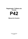
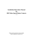
Vango V2051 Converter User’s Manual Guangzhou Gaoke Communications Technology Co.,LTD V2051 Converter Vango Series V2051 interface converter User ’s Manual Production Version: V20510503520 Guangzhou Gaoke Communications Technology Co.LTD supplies overall technical sustainment for the user with open arms; the users can keep touch with the office of GaoKe and contact the customer service in the company directly. Guangzhou Gaoke Communications Technology Co.,LTD. Kate Tin(sales manager) GuangZhou GaoKe Communications Technology Co.,LTD http://www.gktel.com.cn Email:[email protected] [email protected] Tel:86-20-8259 8427 Fax:86-20-8259 9989 MSN:[email protected] SKYPE: kate.tin Address:GAOKE SCI-TEC Park,NO.168 Gaopu Road,510663,Guangzhou,P.R.China V2051 Converter Copyright Copyrighted by Guangzhou Gaoke Communications Technology Company Limited. All rights are reserved. No Part of this document may be reproduced or transmitted in any form or by any means without prior written consent of Guangzhou Gaoke Communications Technology Company Limited. ® is the trademarks of Guangzhou Gaoke Communications Technology Company Limited. No the trademarks may be counterfeited. Announcement of NonResponsibility 免责申明 Guangzhou Gaoke Communications Technology Company Limited reserves the right to change the document from time to time at its sole discretion, and not to make the notice to anyone in advance. V2051 Converter Preface Organization Of This Manual This manual describes the functionalities of V2051 interface converter, V2051 interface converter (single slot) and information about how to configure and test them in network application. Chapter 1 Summary: introduces the characteristic and application of manufacture Chapter2 Main Technical Features: introduce the main technical features of manufacture and predominance compared with congeneric product. Chapter 3 Hardware characteristic: describes the principium、mechanical frame、the main technical specialty and working condition of V2051. Chapter 4 Application: describes the common network and application. Chapter 5 Installation Guide: introduce the facture and installation of power supply, board and interface cable Chapter 6 NMS: introduces the software of NMS simply. Audience This manual is for network administrators, network engineer and technician. Style convention Table 1 Style convention used in this manual Format Meaning \ Multilevel catalogs or menus are separated by ‘\’ character. For instance “file\new\directory” means the menu item “directory” in menu “new” which are in turn in the menu “file”. Used to highlight important area in diagrams. <> 【】 Indicates the input data from operating terminal Indicates one parameter configuration or a function { XX | XX } Indicates a syntax of CLI command options, multiple command options in one “{}”, separated by “|”, means exclusive single selection host(italic) Indicates user specified parameters. e.g. for command: tftp host {get | put} {sys | cfg} filename The host and filename should be replaced by user specified real parameters, such as: tftp 138.0.0.102 get sys vxworks.bin Table 2 Definition of mouse operation Format Meaning Click Pressing mouse quickly and releasing one button of mouse Double click Pressing mouse twice quickly in sequence and releasing one button of mouse Drag Pressing one button of mouse without releasing and move mouse V2051 Converter Table 3 Keyboard operation convention Format Meaning [F] “[]”means certain button of keyboard,such as [F] mean button F of keyboard [Ctrl] + [C] “+”means pressing several button to complete one operation at the same time, so “Ctrl+C” means press ‘Ctrl’ and ‘C’ button at the some time. Flags A set of flags are used throughout this manual and they have the meaning as explained below: Warning: Something important during the operation Notice: Explains and complementation to some content V2051 Converter Content 1. Summary.........................................................................................................................................................7 2. Main technical features .................................................................................................................................7 3. Hardware Characteristic.............................................................................................................................7 3.1 Fundamental...........................................................................................................7 3.1.1 Conversion between E1 and Ethernet .........................................................8 3.1.2 Conversion between E1 and V.35................................................................8 3.1.3 Conversion between V.35 and Ethernet ......................................................8 3.2 Mechanical Framework ..........................................................................................9 3.3 Main Technical Parameter....................................................................................10 3.3.1 2M interface(E1).........................................................................................10 3.3.2 Data Interface.............................................................................................10 3.4 Working Condition ................................................................................................10 4. Network Application ..................................................................................................................................11 5. Installation Guide ......................................................................................................................................11 5.1 Check whether the equipment and spare part are all right ............................... 11 5.2 The connection of power supply wire ................................................................ 11 5.3 Connection of E1 signals ...................................................................................12 5.3.1 Connection of 75Ω signal interface............................................................12 5.3.2 120Ω El interface connection .....................................................................12 5.4 Ethernet interface .................................................................................................13 5.5 V.35 interface........................................................................................................13 6. Judgment and Operation of Failure...........................................................................................................15 6.1 Faceplate indicator light .......................................................................................15 6.2 Definition of switch and jumper ............................................................................16 6.3 Problem of application..........................................................................................18 7. Network Management System...................................................................................................................21 Appendix A ........................................................................................................................................................22 Appendix B ........................................................................................................................................................25 V2051 Converter 1. Summary V2051 interface converter belongs to Vango series that developed by Gaoke Communication Technologies Co., Ltd. V2051 support one E1 interface, one V.35 synchronous interface and one 10BaseT/100BseTX selfadaptive Ethernet interface (If there is no special explanation, hereinafter referred to as Ethernet) V2051 interface converter (If there is no special explanation, hereinafter referred to as V2051) is highly integrated and all of the design use the LSI.It can be pointtopoint configured independently and also be connected with central node of C2810 concentrative Ethernet transceiving system via advanced network manager system to realize the full communication network management while its maintenance is very convenient. Gaoke Communication Technologies Co., Ltd. owns the selfdeveloped IP (Intelligence Property) rights and provides useful resolution that accord with user’s special function requirement. To adapt the daily changing requirement of telecom operation, the V2051 series of our company are updated tightly with changing step. Considering there are still many users that use the old type V2051 of our company, we have a simple comparison and explanation of the slight difference in appendix A and appendix B to avoid the confusion. 2. Main technical features (a) Realize V.35 data or 10BaseT/100BseTX data transparent cutthrough on E1 link. (b) E1 interface supports both framed and unframed mode. (c) Unframed maximal E1 data rate is up to 2048kb/s; Maximal framed E1 data rate is up to1984kb/s with remote network management available. (d) Ethernet interface support 10/100M and Half/Full duplex accord with IEEE802.3 standard protocol. Supporting autonegotiation function and 802.3x flow control method; supporting transparent cutthrough of Ethernet protocol, such as 802.1Q (WLAN), 802.1d, 802.1p, 802.3ad and so on. (e) V.35 interface can choose DCE or DTE mode, and connect with standard V.35 interface of other DTE or DCE. (f) Framed E1 interface can be connected with other Vango equipment which transfers Ethernet data via 2M link to realize the Ethernet bridge function. (g) One facile E1/V.35 BER (Bit Error Rate) Tester is embedded for the detection of E1 link error by a method of transmitting and receiving array of pseudo random codes; (h) V2051 can be in partnership with each other via E1 interface, and also can be pointtopoint connected with the BRG, ETC, V35 units of C2810 central Ethernet transceiving system of our company to realize transparent cutthrough of V.35 data or Ethernet data. 3. Hardware Characteristic 3.1 Fundamental Conversion among interfaces of V2051 is implemented via automatic signal V2051 Converter identification of each interface, completing conversion option between E1 and 10/100M Ethernet interface, between E1 and V.35 interface or between V.35 and Ethernet. 3.1.1 Conversion between E1 and Ethernet V2051’s conversion between E1 and 10/100M Ethernet is aimed at transferring the Ethernet data over E1. Both E1 and Ethernet interface can be configured. Framed E1 interface support, n´64kb/s (n=1~31) , occupying TS1~TS31, and can be connected with bridges of other E1 interfacesupported Vango equipment Unframed E1 interface rates up to 2048kb/s. The work flow is shown as figure 31 10 BaseT/ 100 BaseTX Figure 31 Fundamental of conversation between E1 and Ethernet 3.1.2 Conversion between E1 and V.35 V2051’s conversion between E1 and 10/100M Ethernet is aimed at transferring the V.35 data over E1. Both E1 and V.35 interface both can be configured. Framed E1 interface support, n´64kb/s (n=1~31) , occupying TS1~TS31, and can be connected with bridges of other E1 interfacesupported Vango equipment Unframed E1 interface rates up to 2048kb/s. V2051 can be connected with V.35 interface of the DCE or DTE equipment of other Vango series.. The work flow is shown as figure 32 V.35 Figure 32 Fundamental of conversion between E1 and V.35 3.1.3 Conversion between V.35 and Ethernet V.35/Ethernet conversion of V2051 is aimed at transferring 10BaseT/100BaseTx over V.35 link. The pair of V.35 interface should be configured as one DCE and one DTE. And the clock and data of DTE interface should be adapted to the DCE interface. The flow is shown as 33. V2051 Converter Figure 33 Fundamental of conversion between V.35 and Ethernet 3.2 Mechanical Framework The Framework of V2051 adopts generalpurpose box structure with the size of 202 mm×140 mm×36 mm (W*H*D). It can be put on table or other shelf. The signal interface and alarm led are placed in the front, two 8 digit switch at the side, and alternating power supply at the back.( Shown as figure 34) Figure 34 a) V2051 appearance Figure 34 b) Front view of V2051 Figure 34 c) Back view of V2051 V2051 Converter Figure 34 d) V2051 interface explanation Figure 34 V2051 interface conversation appearance view The back board includes Power supply interface, V35 interface, 2M interface, Network interface, shown as figure 34 c. Power supply interface can choose from 48v DC or 220v AC( 24v DC should be claimed before, we can offer it according to order), 2M interface can choose from 75Ω (BNC, CC4B)or 120Ω(DB9). 3.3 Main Technical Parameter 3.3.1 2M interface(E1) standard rate: 2048kb/s, offset tolerance ±102bit/s. interface: A. 75Ω unbalanced, HDB3 code; B. 120Ω balanced, HDB3 code. 3.3.2 Data Interface show as table 1. Table 1 main technical parameter of data interface Data type V.35 Adaptation type Mode Synchronous multiplex Synchronou s Rate n×64 kb/s,maximal rate 2048 kb/s。 10BaseT/1 Network layer Synchronou 00BaseTx adaptation s 10Mb/s, 100Mb/s。 3.4 Working Condition a) Working voltage :d.c ±48×(1±20%)V or a.c 220×(1±20%)V; ( 24v DC should be ordered) b) Relative humidity: 10%90%, not condensation; c) Environmental temperature: 0°C~40°C; d) Storing temperature: 30°C ~60°C; e) atmospheric pressure: 86kPa~106kPa; V2051 Converter f) power consumption:3 W~5W. 4. Network Application Figure 41 Network application of V2051 V2051 connect with the BRG or V35 unit of the C2810 concentrative Ethernet central node transceiving system, or another V2051, realizing the Ethernet or V.35 interface network bridge function. While central node is C2810 concentrative Ethernet transceiving system and E1 interface work in framed model, the remote V2051 equipment can be managed and configured at central node, if only the uptodate SW and firmware has been equipped. 5. Installation Guide 5.1 Check whether the equipment and spare part are all right 5.2 The connection of power supply wire 220V alternating current power supply connect with power supply cable wire directly. Fix the power supply plug on +48V or 48V power supply wire and insert it in the power supply connection jack. Show as the followed figure. Warning: Only 48V is allowed when DC power supply is required. 24V should not be used unless special order has been made Figure 5 Connection of DC power supply wire V2051 Converter 5.3 Connection of E1 signals 5.3.1 Connection of 75Ω signal interface Cable connected with V2051 E1 interface must be SYV7522, Please Plug the connector into E1 interface of CC4B4G or BNC4G and then fix the screws. The connection can be learnt from figure 52, 53 and 54. The following are the detailed processes. a) According to figure 52, use a knife to cut 7mm of the cable’s cover, be careful not to cut the copper web (connecting the grand to protect), and then cut 2mm of the insulated layer, exposing the cable core. b) Disperse the shield web, and remove the protection cover and the plug cover, weld the cable core to the jointing inside of the plug according to figure 53.Then use some tools to push and compress the copper pipe and make it a little distorted to fix the connection, cover the pyrocondensation glue cover and make it shrink, then put on the protection cover and the plug cover. c) Connect the E1 signal according to figure 54 after the connector is ok. Figure 52 Coaxial cable Figure 53 Facture and weld of coaxial cable connector Figure 54 E1 signal comeout line of CC4B4G 5.3.2 120Ω El interface connection 120Ωimpedance E1 signal is connected directly by DB9, connecting pins V2051 Converter show as table 51. Table 51 120Ω E1 signal output line table Signal explanation Input Output Grand CC4B4G 1、6 2、7 5 5.4 Ethernet interface V2051 provide conversion between Ethernet interface and E1 interface. Framed E1 interface support n´64kb/s (n=1~31) . Unframed E1 interface data rate up to 2048kb/s. All of the rate configurations are realized by the 8bit switch SAI in the inside circuit board. (Shown as figure 62) Ethernet interface connect LAN by twistedpair and accord to IEEE802.3 standard. Faceplate indicator light LTX is data sending indicator and green light flashing or last lighting means Ethernet interface is sending data; LRX is data receiving indicator and green light flashing or last lighting means Ethernet interface is receiving data; LNK is link state indicator and green light lighting means interface connection of the other equipment is right. Pins of RJ45 1 and 2 connection jack are data output of Ethernet interface while 3 and 6 are data output. Warning: For the high interface rate, 1 and 2 must be a twistedpair, 3 and 6 also must be a twistedpair while connecting the cable. (Cable corresponding relationship show as figure55) Pins 3 and 6 of RJ45 connection jack at back board are Ethernet data input, while 1 and 2 are output. V2051 support autocross identification of Ethernet interface cable and both direct and cross cable can be chose , no matter connecting with DTE or DCE cross direct Figure 9 Connection of 10/100M Ethernet port and DTE/DCE 5.5 V.35 interface V.35 synchronous data interface supported by V2051(V35) connect exterior line via DB15 needle negative connection jack, provide n×64kb/s ( unframed maximal rate 2048kb/s, framed maximal rate 1984kb/s), occupy n 64kb/s time slot, and the occupied time slot and rate are set by switch or NMS. Indicator light of this board lighting means V.35 signals inputting the channel and V2051 Converter flashing at about 2Hz means V.35 data is in loopback mode.(please refer to the next section about indicator for details) . V.35 interface is a synchronous data interface, differed from the direction of clock connected by DTE and DCE, and can be configured through NMS. Table 52 and table 53 are corresponding pins . V.35 interface is synchronous data interface, and differ from the direction of clock connected by DTE and DCE. Table 2 Connection of DTE (DCE port) 15 pins (pin number) Name 1 GND 2 Explanation Corresponding level V.35 pin Dual direction Protect (shield) A SDA To V2051 Send data A P V.35 9 SDB To V2051 Send data B S V.35 5 CTS From V2051 Sending is getting D ready V.28 12 DSR From V2051 V2051 is getting E ready V.28 12 DCD From V2051 V2051 receiving F is ok V.28 8 GND Dual direction Signal (shield) 4 RDA From V2051 Receive data A R V.35 11 RDB From V2051 Receive data B T V.35 14 SCA From V2051 Sending clock A Y V.35 15 SCB From V2051 Sending clock B AA V.35 6 RCA From V2051 Receiving clock A V V.35 13 RCB From V2051 Receiving clock B X V.35 To V2051 Exterior synchronization clock A V.35 3 SCEA Direction V2051 Converter ground ground B U 10 SCEB To V2051 Exterior synchronization clock B W V.35 Note: Pins not be lined out needn’t to be connected. Table 3 Connection of DCE (DTE port) 15 pins Name (pin number) Direction Explanation Corresponding level V.35 pin 1 GND Dual direction Protect ground A (shield) 2 RDA To V2051 Receive data A R V.35 9 RDB To V2051 Receive data B T V.35 4 SDA From V2051 Send data A P V.35 11 SDB From V2051 Send data B S V.35 Data terminal is H getting ready V.28 V.28 5 DTR From V2051 12 RTS From V2051 Requiring sending C 8 GND Dual direction Signal ground B 6 SCEA From V2051 Exterior synchronous clock A U V.35 13 SCEB From V2051 Exterior synchronous clock A W V.35 3 RCA To V2051 Receive clock A V V.35 10 RCB To V2051 Receive clock B X V.35 Note: Pins not be lined out needn’t to be connected. 6. Judgment and Operation of Failure 6.1 Faceplate indicator light V2051 interface conversion device has consummate autoalarm function, and the V2051 Converter equipment status is indicated by the LED in the front board. Explanation of the faceplate indicator light is shown as the table. And please refer to table 61 on how to get the failure indication via indicator light. Table 61 panel indication light Indicator light Meaning PWR Green light last lighting means the power supply working is ok. TD Green light last lighting means V.35 interface is sending data (DTE interface output or DCE interface input); Green light flashing means E1 and V.35 interface is looping outwards to provide link test. RD Green light last lighting means V.35 interface is sending data (DTE interface output or DCE interface input); Green light flashing means E1 and V.35 interface is looping outwards to provide link test. SG Green light last lighting means E1 signal is inputting and working ok. Green light flashing means framed E1 signal is inputting but frame is asynchronous. RMA Yellow light lighting means framed E1 signal corresponding interface is alarming LNK Green light lighting means interface connected with other equipment is working ok LTX Green light flashing or last lighting means Ethernet interface is sending data LRX Green light flashing or last lighting means Ethernet interface is receiving data LP Green light last lighting means self E1 interface is looping outwards; Green light flashing means examined corresponding E1 interface is looping (Only transmitting Ethernet data is available.) BER Red light flashing quickly means tested E1 link has error code (Only available in BER test mode) Red light flash slowly means there is error in CRC checkout of Ethernet HDLC frame (Only available when transmitting Ethernet data.) 6.2 Definition of switch and jumper V2051 has two 8bit switch for the configuration of each port. V2051 Converter Table 62 SAI switch configuration Switch Meaning 1 V.35 interface choice:OFF=DCE mode;ON=DTE mode 2 E1 transmission clock choice: (1) Ethernet switch E1 model: OFF=synchronizing to E1 receiving clock;ON=master clock (2) V.35 switch E1 model: OFF= synchronizing to E1 receiving clock ON =master clock (DCE) / synchronizing to V.35 receiving clock (DTE)(Fifth bit of SA2 is OFF); ON =master clock (DTE) / synchronizing to V.35 receiving clock (DCE)(Fifth bit of SA2 is ON) SA1 The second First bit of The fifth bit of bit of SA1 SA1 SA2 3 Synchronizing to V.35 clock ON OFF(DCE mode) ON Master clock ON OFF(DCE mode) OFF Master clock ON ON (DTE ON mode) Synchronizing to V.35 clock ON ON (DTE OFF mode) Framed E1 choice,OFF=framed, ON=unframed; E1 rate choice(ON=0;OFF=1), The forth bit is MSB, the eighth bit is LSB. 4 5 6 7 8 Framed: Unframed only 64K: 00001, 128K: 00010, 192K: 00011, 256K: 00100, support 2048K : 320K:00101,384K:00110,448K:00111,512K: 00000 01000,576K:01001,640K:01010,704K:01011, 768K:01100,832K:01101,896K:01110,960K: 01111,1024K:10000,1088K:10001,1152K:10010, 1216K: 10011, 1280K: 10100, 1344K: 10101, 1408K: 10110,1472K:10111,1536K:11000,1600K:11001, 1664K:11010,1728K:11011,1792K:11100,1856K: 11101,1920K:11110,1984K:11111 Framed E1 signal configured by switch occupy time slot continuously. i.e., 64K occupying TS1,TS2, 256K occupying TS1~TS4. Configuring 1~31 time slot independently can be implemented by uptodate NMS. V2051 Converter Table 63 Configuration of SA2 Switch Meaning 1 Link loop OFF Normal mode 2 Bit Error Rate Normal test of E1/V.35 mode SA2 link ON working E1/V.35 data loop outwards working BER test mode of E1/V.35 3 CAS configuration E1 without CAS The 16 th time slot of framed E1 transmit CAS 4 DCD configuration DCD keeps high DCD is high when effective E1 signal is detected and low otherwise 5 Ethernet IEEE802.3x interface flow control is on control configuration 6 Ethernet interface autonegotiation flow Flow control is off Autonegotiation Not autonegotiation 7 Rate 100Mbps configuration of Ethernet interface 10Mbps。 8 Half/Full duplex Full duplex configuration of Ethernet interface Half duplex Note: The red button in the front of V2051 has the same function as SA21. Pressing down the button means normal working condition, while pulling up means E1/V.35 data loop outwards. Otherwise, inside of V2051 interface conversion device box, there are several jumper configured in the circuit board and J1/J2/J14 are provided to the users. When being suspicious of the 2M interface corresponding connection of equipment produced by other company, try to change the three jumper to settle the problem. The first bit configuration of SA21 switch will be unavailable if J15 is OFF. And the other jumpers should be kept default. J15, J13, J9, J5 are ON, 2 and 3 of J10 are ON, J7 and J8 are OFF. 6.3 Problem of application Usual failures in V2051 adjustment can be judged by the status of indicator light, table 64 explain it in details. We hope the simple instruction can be V2051 Converter helpful for equipment maintenance. V2051 Converter Table 64 Failure appearance and disposal of V2051 Indicator light Failure appearance and disposal SG Light not lighting means there is no data input of 2M interface. Whether there is signal in E1 input interface, and whether remote equipment has sent data, including examine remote sending equipment on or off should be examined. Light flashing means framed signal is losing synchronization, try to examine clock configuration and framed model is right or not. RMA Yellow light lighting means remote alarm of framed E1 signal. If there isn’t any obvious alarm, looping section by section to remove the problem is recommended. LNK Green light lighting means connection with other equipment is ok. If the light is not up, examining the interface and joint line connected with V2051, we recommend to solve the problem by changing interface or joint line. LTX Green light flashing or last lighting means Ethernet interface is sending data, otherwise should examine whether there is alarm in E1 input interface, and data is right or not. LRX Green light flashing or last lighting means Ethernet interface is receiving data. If it keeps off, you should examine whether the remote equipment is sending data to the interface, such as whether the equipment is startup. Besides, you can examine network line is ok or not TD Green light flashing means E1 interface and V.35 interface is looping outwards to provide link testing. Green light last lighting means V.35 interface is sending data to DCE(V2051 is DTE at this time)or receiving data from DTE (V2051 is DCE at this time). Keeping off means there is no data transmitting via V.35 interface, you should examine remote V.35 equipment and whether there is data input of E1 input interface (framed and unframed were included) RD Green light flashing means E1 interface and V.35 interface is looping outwards to provide link testing. Green light last lighting means V.35 interface is sending data to DTE(V2051 is DCE at this time)or receiving data from DCE (V2051 is DTE at this time). Keeping off means there is no data transmitting via V.35 interface, you should examine V.35 corresponding equipment and whether there is data input of E1 input interface (framed and unframed were included) V2051 Converter LP Green light flashing is loop indicator, pushing the first bit of switch SA2, E1 and V.35 interface data will loop outwards at the same time. When transmitting Ethernet data, green light flashing means corresponding E1 data is looping inwards; At this time, if you have configured it before, you needn’t care about it; If you haven’t configured, looping caused by wrong operation of the transmit line should be examined. BER Red light flash quickly in BER test mode means error code in 2M transmit line, examining whether the corresponding interface has configured loop and E1 link is right or not; Transmitting Ethernet data, not in BER test mode, red light flash slowly means CRC error check of HDLC frame is detected. Try to find whether time slot configuration of the two end of E1 accord strictly to configuration of CAS. 7. Network Management System About remote V2051, if it work in framed mode and within a network controlled by C2810 of central node, the NMS information transmit via C2810 framed E1 signal of the central node. For configuration in details please refer to C2810 user manual. If the network is setup with only two same V2051, NMS can not be used. V2051 Converter Appendix A Instruction of different type of V2051 interface conversion device Besides the most uptodate V2051, our company has produced three different type of interface transition device, instruction of their difference as followed。 Old type of V2051 interface conversion Appearance, faceplate indicator lights and their definition of old type of V2051 interface conversion (print board specification number is GKT 7825372C) are as same as the new, the difference between them are: a) SA2 switch of the old type is only 4digi; b) Old type only support 10BaseT of IEEE 802.3, not supporting 100BaseTX model c) The latter 4 bit of new V2051 is used to configure Ethernet model, but the configuration is not useful for the old type since it supports 10BaseT model only. Besides, PCB board in the box of old type configured a jumper J1 to configure clock model of V.35 interface. Warning: New V2051 (print board specification number is GKT7825372C, hereinafter referred to as –C) and the newest V2051(print board specification number is GKT 7825372D, hereinafter referred to as –D), besides their appearance is different, their jumper definition is different too. J8 of –C specification is reposition switch. When J8 is closed, system is in reposition state and going back to work after opened. Making use of the jumper can warm boot equipment without closing or opening the power supply switch. Please don’t change the jumper configuration casually, configuring it followed as the default configuration, other functions and switch configuration are as the same. Switch definition of the old type V2051(print board number is GKT 7825372A) are as followed: V2051 Converter Table A1 Switch configuration of V2051 old type Switch Meaning 1 2 SA1 V.35 interface choice :OFF=DCE mode;ON=DTE mode E1 transmission clock choice: (1) Ethernet switch E1 model: OFF=synchronizing to E1 receiving clock;ON=master clock (2) V.35 switch E1 model: OFF= synchronizing to E1 receiving clock ON =master clock(DCE)/ synchronizing to V.35 receiver clock(DTE) (J1 in box: OFF) ON =master clock(DTE)/ synchronizing to V.35 receiver clock(DCE) (J1 in box: ON) The second The first bit of J1 bit of SA1 SA1 Synchronizing to V.35 clock ON OFF(DCE mode) ON Master clock ON OFF(DCE OFF mode ) 3 Master clock ON ON (DTE ON mode) Synchronizing to V.35 clock ON ON (DTE OFF mode) E1 mode choice (framed or unframed),OFF=framed, ON=unframed. E1 rate choice(ON=0;OFF=1),The forth bit is MSB, the eighth bit is bottommost bit 4 5 6 7 8 Framed : Unframed: 64K: 00001, 128K: 00010, 192K: 00011, 256K: 00100, 2048K:00000 320K: 00101, 384K: 00110, 448K: 00111, 512K: 01000, 576K: 01001, 640K: 01010, 704K: 01011, 768K: 01100, 832K: 01101, 896K: 01110, 960K: 01111, 1024K: 10000, 1088K:10001,1152K:10010,1216K:10011,1280K: 10100,1344K:10101,1408K:10110,1472K:10111, 1536K:11000,1600K:11001,1664K:11010,1728K: 11011,1792K:11100,1856K:11101,1920K:11110, 1984K:11111 Framed E1 signal configured by switch occupy time slot continuously, i.e., 64K occupying TS1,TS2, 128K occupying TS1 and TS2, 256K occupying TS1~TS4. Configuring 1~31 time slot independently can be implemented by uptodate NMS. V2051 Converter Table A2 SA2 switch configuration of V2051 old type Switch Meaning OFF 1 Loop Normal working E1/V.35 data loop outwards mode 2 E1 BER test Normal working E1/V.35 BER testing mode mode 3 CAS configuration Framed E1 The 16 th time slot of framed E1 without CAS transmit CAS 4 DCD configuration DCD keeps high DCD is high when effective E1 signal is detected and low otherwise SA2 V2051 Converter ON Appendix B V2051 interface conversion device (single slot) Appearance of V2051 interface conversion device (single slot) greatly differs from the three types V2051 instructed above. Face of it is a black single box(show as figure B1), after loosening the screw in the faceplate, the inside PCB board can be inserted directly. (From up to down, ETC front board, V35 front board and back board of them) Figure B1 V2051 interface conversion device (single slot) system board figure V2051 interface conversion device (single slot) has two type. One is ETC, and it can transmit 10BaseT/100BaseTX Ethernet signal on E1 link; Another is V35, and it can transmit V.35 synchronous n×64k signal on E1 link. The definition of switch and indicator light are also very different, instruction as follows: ETC(single slot) has three group of switch. There is a group of 8digi switch in main control board and two group of 4 bit switch in the insertable board. Table B1 SW1 configuration of ETC main control board Switch Meaning Framed E1 signal CAS choice:ON=CAS including in 16 th time slot;OFF= CAS 1 not including in 16 th time slot。 E1 sender clock choice : ON=synchronizing with E1 receive signal ; 2 OFF=master clock V2051 Converter S 3 W1 E1 model choice ( framed or unframed): ON=framed;OFF=unframed E1 rate choice (ON=1;OFF=0) , The forth bit is MSB, the eighth bit is bottommost bit 4 Framed: 64K: 00001,128K:00010,192K:00011,256K: 5 00100,320K:00101,384K:00110,448K:00111, 512K: 01000, 576K: 01001, 640K: 01010, 704K: 01011, 768K:01100,832K:01101,896K:01110, 960K: 6 01111,1024K:10000,1088K:10001,1152K:10010, 1216K:10011,1280K:10100,1344K:10101,1408K: 7 10110,1472K:10111,1536K:11000,1600K:11001, 1664K:11010,1728K:11011,1792K:11100,1856K: 8 11101,1920K:11110,1984K:11111 Unframed: 2048k:00000 Framed E1 signal configured by switch occupying time slot continuously. Such as 64K occupy TS1,TS2, 128K occupy TS1 and TS2, 256K occupy TS1~TS4. Configuring 1~31 time slot independently cooperate with the up to date NMS. Table B2 SW1 configuration of ETC board ( configuration of Ethernet model) Switch Meaning OFF Branch 1 Adaptive Adaptive model board configuration of Ethernet SW1 interface ON Unadaptive model 2 Rate 100M ( Neglecting 10M (The third bit configuration of configuration of the must be OFF) Ethernet third bit) interface 3 Rate 10M (The second 100M ( The second configuration of bit must be ON) bit must be OFF) Ethernet interface 4 Duplex Full duplex model configuration of Ethernet interface Half duplex model Table B3 SW2 configuration of ETC board (configuration of MII interface model) Switch Meaning OFF V2051 Converter ON Branch 1 Adaptive board configuration SW2 MII interface Adaptive model of Unadaptive mode (recommend) 2 Rate configuration MII interface 100M of (recommend) 10M 3 Duplex configuration MII interface Full duplex Half duplex of (recommend) 4 Flow control of Starting and using Not using configuration of 802.3 flow control control MII interface (recommend) flow Otherwise, there is two independent jumper configured in circuit board and used for loopback mode and BER test mode respectively. Configuration is as follows (ON means jumper is shorted, OFF means jumper is cutoff); J1: Loop, OFF means normal working model, ON means error code testing model. If chose ON at the same time, working in Loop model, tester is shield. V35 equipment (single slot)has two group of switch, one is 8 bit, another is 4 bit. Table B4 SW1 configuration of V35 Switch Meaning 1 V.35 interface choice:OFF=DCE mode;ON=DTE mode 2 E1 error code tester model: ON=error code tester model; OFF=normal working model) SW1 3 E1 model choice (framed or unframed):ON=framed; OFF=unframed. E1 rate choice(ON=1;OFF=0) ,The forth bit is MSB, the eighth bit is bottommost bit 4 5 6 7 8 Framed: Unframed: 64K: 00001,128K:00010,192K:00011, 2048K:00000 256K: 00100, 320K: 00101, 384K: 00110, 448K: 00111, 512K: 01000, 576K: 01001, 640K: 01010, 704K: 01011, 768K: 01100, 832K: 01101, 896K: 01110, 960K: 01111, 1024K:10000,1088K:10001,1152K: 10010,1216K:10011,1280K:10100, 1344K:10101,1408K:10110,1472K: 10111,1536K:11000,1600K:11001, 1664K:11010,1728K:11011,1792K: 11100,1856K:11101,1920K:11110, 1984K:11111。 V2051 Converter Framed E1 signal configured by switch occupying time slot continuously. Such as 64K occupy TS1,TS2, 128K occupy TS1 and TS2, 256K occupy TS1~TS4. Configuring 1~31 time slot independently cooperate with the up to date NMS. V2051 Converter Table B5 SW2 configuration of V35 Switch Meaning 1 E1 sender clock choice: 1=ON, 2=ON:synchronizing with E1 receiver clock; 2 1=OFF,2=OFF:local master clock ; SW2 1=ON, 2=OFF: synchronizing with V.35 clock; 1=OFF,2=ON: synchronizing with V.35 clock; 3 4 Framed E1 signal CAS choice: ON=CAS including in 16 th time slot; OFF= CAS not th including in 16 time slot。 Besides, inside circuit board of V35 interface conversion device configured a jumper J1, using to enter outwards loop model. Configuration as follows: OFF means normal working model, ON means data of E1 interface is loop outwards. If J1 jumper and bit NO.2 of V35 SW1, the equipment enter in E1 outwards loop model, and tester is shield. Faceplate indicator light of ETC V2051 interface conversion device (single slot) show as the followed table. Table B6 ETC faceplate indicator light Indicator light Meaning LNK Link state indication, green light lighting means interface connection with other equipment is right RX Green light lighting means Ethernet is receiving data from the corresponding equipment TX Green light lighting means Ethernet is sending data from the corresponding equipment DUP Green light lighting means Ethernet interface is building full duplex connection. RMA Yellow light lighting means corresponding interface alarm of framed E1 signal LIS Red light last lighting means no E1 signal inputting; Flashing means framed E1 signal is asynchronous. Faceplate indicator light of V35 V2051 interface conversion device (single slot) show as the followed table. Table B7 V35 faceplate indicator light Indicator light RX Meaning Green light last lighting means V.35 interface is receiving data (DTE model)or sending data (DCE model); Green light flashing means E1 and V.35 interface is looping outwards to test the link. V2051 Converter TX Green light last lighting means V.35 interface is receiving data (DCE model) or sending data (DTE model);Green light flashing means E1 and V.35 interface is looping outwards to test the link. RMA Yellow light last lighting means corresponding interface alarm of framed E1 signal LIS Red light last lighting means no E1 signal inputting in; Flashing means E1 signal frame is asynchronous. V2051 Converter