1
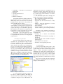
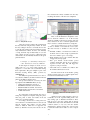
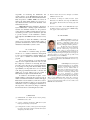
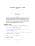
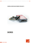
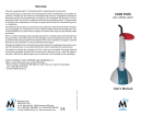
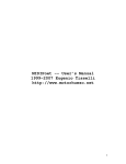
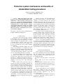
Protection system maintenance and benefits of
standardized testing procedures
Eugenio Carvalheira, OMICRON, USA
Cord Mempel, OMICRON, Austria
Abstract -- This paper discusses some challenges faced by electrical distribution utilities in the
maintenance of their protection system assets. In
order to set a proper and efficient maintenance
program two important aspects should be taken in
consideration: have a system in place to manage
and document maintenance activities and establish
standardized protective relay testing procedures.
This paper presents a solution that can be used to
overcome these challenges.
Index Terms – Protection Systems, Standardized Test
Templates, Maintenance Management
I. INTRODUCTION
Protection system components play a vital role
in the reliability of the power system. Each component
involved shall be tested and maintained in a timely
manner according to the applicable industry or company standards. This is essential to ensure proper operation of the system, to keep it in good working condition and to maximize the power system’s reliability
and availability.
The electrical distribution utilities have been
facing several challenges to accomplish the task of
keeping the system well maintained and reliable. New
regulatory requirements, pressure to reduce costs, lack
of personnel and increasing complexity of the system
are some of the challenges they have to deal with.
An additional challenge faced is the technological evolution of the system, as for example of the
protective relays. Relays have evolved from electromechanical to multifunctional numerical technology.
The way how protective relay testing is done has been
changing over the years due to this technological
evolution.
Ten to twenty years ago the tests were performed by the testing personnel almost manually. The
relay test quantities were hand calculated and a passive
test set (comprised of resistive loads, mechanical phase
shifters and variable autotransformers) was manually
operated. The operating characteristics of electromechanical relays were shaped by resistor, inductor and
capacitor networks while springs and levers defined
the operating times. A small number of parameters had
to be checked. For documentation of test results, these
small number of measured parameters were entered
manually in a test protocol, signed by the test personal
and archived.
With the appearance of modern multifunctional
numerical relays the number of parameters and the
complexity of protection functions have increased
drastically. The protection relay has incorporated a lot
of control and automation tasks. Programmable logic is
used for building protection schemes. Deep knowledge
about the relay algorithms, functions and logics are
required for testing [3]. The number of test results to
be documented have increased as well. To overcome
such challenges, utilities need to use appropriate
testing and database maintenance tools.
Nowadays modern test equipment include electronically regulated voltage and current sources that
provide the accuracy and the output power required to
test all components of the system. Ease of use test
equipment software provide the capability to run
automated tests controlled by computer software [2].
This allows the realization of more sophisticated tests.
The use of pre-defined standardized test plans
is essential for an efficient maintenance program and
to increase traceability and reproducibility of testing. A
user-friendly database management system is also of
great importance for storing the standard test plans,
keeping track of all maintenance activities and managing documentation of test results in a central place.
II. STANDARDIZED TEST PLANS
As the complexity of protective relays has risen,
the need for standardization increased. By establishing
their own standard testing procedures, that meet
company specifications, the electrical utilities have a
lot of additional benefits:
- Save time of protection engineers on developing a
test
- Testing quality can be better controlled and
improved
- Working together as a team is easier, as everyone
uses the same test plan and the same test protocol
- Company know-how can be added to the standard
and gets automatically documented
The user should define two levels of standardization. First a standard on how to test dedicated
protection functions and then a standard on how to test
specific protection applications (e.g. line or
transformer protection).
An example is the standardization of the test for
a transformer differential protection function. A
standard procedure may be:
1
- Configuration or stabilisation test (blocking for
external faults)
- Pickup test
- Operating characteristic test
- Trip time test
- Harmonics blocking test
The standard should also include the fault loops
and transformer sides to be tested. Moreover, the
number and position of test shots have to be defined.
In additional to the "How to test", some general points
can be added like safety procedures.
The development of a testing standard and consequent definition of testing practices strongly depends
on two different factors: the testing philosophy of the
company and the type of test that will be performed.
The requirements are different for test plans that will
be used in type or factory acceptance tests, in commissioning tests or in routine maintenance activities.
Independent of the testing philosophy used,
protection engineers should have in mind some testing
tool requirements they need as basis for designing new
testing standards.
A. Testing tool requirements
The test standard defined by the utility can be
documented as a preconfigured test plan. It can be
defined for specific relay types or specific applications. These standard test plans should contain information about the relay under test, its setting parameters, how to test each protection function and schemes,
instruction on test connections, safety instructions and
recovery post-test instructions. The protection engineer
should be able to get all this information and tests
combined in a unique overall document as shown in
¡Error! No se encuentra el origen de la referencia..
After performing the test he should be able to easily
generate a test report for documenting the test.
Picture 1
disabling protection functions or changing the route of
information to binary outputs should be avoided. It
ensures not only individual functions will be tested but
the overall scheme and the influences one function
may cause on another.
In order to accomplish these challenges, the
testing tools should meet some basic requirements:
- Free-configurable test templates with reporting
- Relay models are available
- Automated test and assessment based on relay
settings
- Ability to incorporate instructions to the test
document (text, pictures, files)
- Static simulations
- Transient simulations for testing under close to
realistic conditions (e.g. Power Swing simulations)
Depending on the application and technology
used, the advanced testing tools should meet further
requirements, like:
- Searching test of distance and differential
characteristics
- Overall overcurrent characteristic depending on
the fault type
- Testing with IEC 61850 GOOSE and Sampled
Values messages
- Real simulation of CT saturation
- Simulation of Power Quality phenomena
B. Relay Models
A relay model should contain a place to enter
the specific relay setting parameters. Based on these
specific settings, the relay is modeled and represented
within a common representation independent of
manufacturer. As result of these modeling all protection characteristics are built up and test parameters are
calculated. The user does not have to always re-think
how to test the relay, but all he needs to do is enter the
relay settings and all the test will be filled out automatically.
The concept of the relay models and automatically calculation of characteristics based on the relay
settings is shown in Picture 2.
Example of a Test Document
A very important target should be testing the relay under its operational conditions. That means, the
relay should be tested without having its settings or
configuration changed for the test. Modifications like
2
tance characteristic already available from the relay
modeling, the addition of the new test is simplified.
Picture 3
Picture 2
Relay Model Concept
After the protection engineer has parameterized
the relay under test using the relay software, he enters
the relay settings in the test tool. Ideally, the user has
to enter the relay settings in the same structure as in the
relay manufacturer software. It can be done manually
or using automatic import functionality, in case the
relay software provides an export of them. The relay
characteristics are automatically calculated at the given
parameterization.
C. Example of a Standardized Testing Procedure: Test Plan for a Schweitzer SEL-421
In this chapter an example is shown on how a
utility made use of a given testing template and
adapted it to create their own test standard meeting
their requirements. The given template is part of the
Protection Testing Library (PTL) provided by
OMICRON [4].
The utility had specified that the test of auto reclose function (ANSI 79) should be included in the test
plans for the SEL 421 distance relays.
The protection functions covered by the existing template in the OMICRON library are [4]:
- 21 Phase/Ground Distance protection
- 50/67P Phase Instantaneous Overcurrent
- 50/67G Residual Ground Inst. Overcurrent
- 50/67Q Negative Sequence Inst. Overcurrent
- 51 Time Overcurrent
First of all, the Hardware Configuration of the
test set should be checked to see if all necessary
signals are available for the test. For testing of the auto
reclose function, the close command signal from the
relay is needed to evaluate the function's closing time.
One option for this test is to create a sequence
of states to simulate a successful auto reclose cycle.
The states necessary to simulate a 1-shot re-closure
are:
- Pre-Fault: simulates a nominal load condition; it
should be run for a time enough to guarantee the
auto reclose function goes to a reset stage.
- Fault: simulates a Zone 1 trip condition. This state
is triggered by the trip signal.
- Pole open interval: circuit breaker opened
condition; during this state the close command is
expected from the relay, that will trigger the
sequence to jump to next state.
- Successful reclose: nominal load condition after
the circuit breaker has been closed.
The time between the circuit breaker opening
and the receiving of the close command signal can be
measured and automatically assessed.
Picture 4
It is important to mention that the user may rearrange the complete test template, change the predefined test points or delete test modules if the test
strategy does not fit his demands.
According to the list above, testing of the auto
reclose function is not included. However, the user can
find the complete relay settings, even the settings
related to functions which are not supported (see
Picture 3). With the necessary data and also the dis-
Reclosing settings in the testing tool
Sequence of States and automatic update of
parameters
All the necessary testing parameters can be automatically set in the sequence linking them to the
relay settings part, as illustrated in Picture 4. These
links are done to the relay settings that are already
available in the relay model. The definition of the fault
condition (State 2) is very easy since the distance
characteristic is already modeled. It is only necessary
to define the fault location relative to Zone 1 impedance.
3
Picture 5
Detail and Impedance View of Fault state
The new created modules can be added to the
test template. The user can configure the module to be
enabled only if the reclosing function is enabled at the
specific site by using the linking functionality. If
desired, other modules can be added to test the auto
reclose function when it is used with two or more
numbers of re-closure cycles.
Picture 6
right up to date test plan, populates it with the proper
relay settings and has easy access to additional instructions and documentation.
There are several software tools on the market
addressing these needs. Many of them offer additional
features and benefits, however many such tools are not
very user friendly and require extensive training to use
them. Some tools are not very helpful when utilities
have to provide evidence on maintenance and corrective actions done (e.g. when a maloperation has occurred or for an audit).
It is important for a maintenance management
tool to include not only protective relays but also all
other components that form the protection system:
- Communications systems necessary for correct
operation of protective functions
- Voltage and current sensing devices providing
inputs to protective relays
- Station dc supply associated with protective
functions (including station batteries, battery
chargers, and non-battery-based dc supply)
- Control circuitry associated with protective
functions through the trip coil(s) of the circuit
breakers or other interrupting devices
SEL 421 template with new Auto-Reclose tests
As the given SEL 421 template supports the
import of relay settings, the new integrated tests of the
auto reclose function can also make use of this feature.
Changed relay settings will be updated immediately in
all test modules of the test plan.
III. MAINTENANCE MANAGEMENT
Due to large number of components involved in
the protection system, management maintenance
activities and proper documentation of test results may
become very complex.
A. Requirements for a maintenance management tool
Utilities may need a tracking tool to help
schedule the maintenance activities for all protection
system components, and to store all the documentation
of such activities.
Tool support is also essential for the protection
tester in the field: he should get support to select the
Picture 7
Typical protection system (indicating possible error
sources that can lead to relay maloperation)
Correct functioning of all components of the
protection system is required to securely clear a
network fault. Picture 7 shows a typical protection
system with possible sources of errors. Therefore the
whole system should be considered during maintenance.
B. ADMO - A database solution for protection system maintenance
Even with automated test plans and excellent
testing tools, testing and maintenance of the protection
system is a challenging task. Therefore ADMO has
been specially designed to support this task and to
provide the most intuitive and easy to use solution
possible. Key features are:
- Support protection testing at site
4
- Easy and intuitive document management of the
protection system
- Easy and intuitive management of test documents
- Planning and management of maintenance
activities
The ADMO main screen (Picture 8) provides the
maintenance status overview:
- For all components of the protection system
- For a certain location (e.g. a substation)
- For components matching a filter condition (e.g.
for a certain type, a responsible person etc.)
In this overview the yellow bar shows all devices due for maintenance, the red bar the devices already
overdue and the magenta bar devices where data is
incomplete.
Picture 8
Overview of maintenance status of the overall
system at a glance with ADMO
Once a specific asset is selected, ADMO shows
the maintenance history of this relay. The user sees
when the next maintenance is due or overdue and gets
direct access to test documents when clicking on the
related maintenance event (Picture 9).
Picture 9
Asset maintenance history and test documentation
for the last maintenance in ADMO
C. Supporting protection testing
Using standardized and automated test plans (as
described earlier) already supports the tester a lot:
- The test procedure (test points) is already defined
- The test plan includes instructions and gives
guidance for the tester
- The test plan adapts automatically to the relay
settings
- The test steps and the relay settings are included in
the test document ensuring traceability and
repeatability
- The test report is generated automatically
ADMO complements the testing software as
follows:
- When the tester starts testing (creates a
maintenance event in ADMO), ADMO provides
him all test plans suitable for this relay type
- In addition ADMO provides easy access to other
documents related to this relay type or location
(e.g. relay manual, cubicle drawings, substation
information)
- After selecting the test plan the tester can directly
start the testing software from ADMO
- Before starting to test the tester needs to load relay
settings into the test plan. ADMO provides direct
access to import of setting files assigned to the
tested relay
- The tester can add additional information and files
to document actions done (or problems occurred
and solved)
- Test results are stored back automatically in
ADMO and can be synchronized with the central
database later
- In case of unclear protection behavior ADMO
allows access to other test documents (comparison
with other relays tested)
- ADMO allows definition of follow-up activities
and shows the test status (e.g. if the final
assessment should be done later in the office
(Picture 10)
Picture 10 Maintenance event with test document, final Event
Status still open
D. Regulatory Compliance in North America
and NERC PRC-005
In North America (USA and parts of Canada),
there is an independent non-profit organization that is
5
responsible for monitoring the maintenance and
security practices of the Bulk Electrical System; this
entity is known as the North American Electric Reliability Corporation or NERC. NERC was formed in
1968 by the electric utility industry as a response to a
major blackout which occurred in the Northeast of the
United States in 1965.
NERC PRC-005 is the standard for “Protection
System Maintenance” defining required maintenance
activities and minimum intervals for the protection
system. It enforces utilities in North America to have a
documented protection system maintenance plan and
to provide evidence on all maintenance activities.
Noncompliance with NERC standard can lead to heavy
fines.
Intended to ensure the reliability of the bulk
electric power system this standard mainly applies to
generation and transmission, however it is influencing
maintenance in distribution systems as well.
IV. CONCLUSION
The definition of standard testing procedures
and the use of a database maintenance management
tool are very important things electrical utilities may
do in order to establish an efficient maintenance
program.
The protection functions of modern numerical
relays are more complicated than in the older ones and
the complexity of functions is increasing with every
new relay version. For this reason testing standardization is getting more important. The traceability and the
reproducibility are important factors for an efficient
work. The paper illustrated that with a solid base and
making use of proper testing tools it is possible to
build standard test plans with a minimum effort.
In addition to the standard test plans, a userfriendly database system helps the protection group at
utilities to track their maintenance activities. The paper
illustrated how such a database system can be used for
archiving the standard test plans (to be used in future
maintenance events), for managing the maintenance of
all components of the system according to established
time intervals and for documenting the test results.
[4] SEL-421 Distance Protection Test Template User Manual.
OMICRON electronics, 2014
[5] R. Bhandari, C. Mempel, B. Jenkins. Protection System
Maintenance: Test, Maintain, and Comply with NERC Reliability Standards. International Protection Testing Symposium
2013, USA
[6] Track it or lose it, ADMO – the new NERC PRC-005 compliant database solution for protection systems. OMICRON Magazine, page 26, Volume 3 Issue 2 2012
VI. BIOGRAPHIES
Eugenio Carvalheira received his
BSc in Electrical Engineering from the Federal
University of Pernambuco, Brazil, and his
MSc in Computational Engineering from the
University of Erlangen-Nuremberg, Germany.
He started his career as a Project Engineer responsible for the design, implementation and commissioning of protection and
control systems for electrical substations and
power plants. In 2008, he joined OMICRON electronics Germany as
Training and Application Engineer designing and developing test
automation solutions for protection relays and responsible for the
IEC 61850 training courses of OMICRON.
He is presently Regional Application Specialist and Training Manager for Latin America with OMICRON electronics Corp.
USA in Houston, TX.
Cord Mempel received his Diploma
in Electrical Engineering at the Technical
University of Braunschweig, Germany. He
started his career at Siemens Berlin in
development of numerical protection relays.
This was then followed by further positions
at Siemens in Nuremberg, including sales
and project management for machine
protection and then business development for
Siemens protective equipment in the Middle East and Africa. In
2004, he joined OMICRON in Klaus, Austria. He is working in
product management in the field of power system protection testing
with a focus in data management solutions. Cord is a member of the
IEEE PES and the German VDE.
V. LITERATURE
[1] OMICRON PTL User Manual (Protection Testing Library).
OMICRON electronics, 2014
[2] A Survey of Relaying Test Practices. IEEE Power Systems
Relaying Committee Report, January 2002
[3] B. Bastigkeit. How a library of Relay Specific Test Templates
Can Support the Protection Engineer. International Protection
Testing Symposium 2007, Austria
6