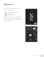
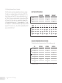
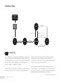
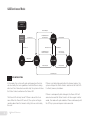
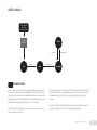
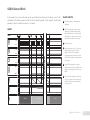
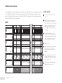
1
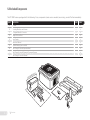
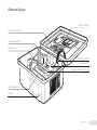
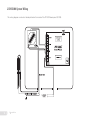
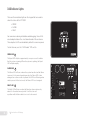
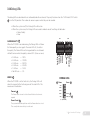
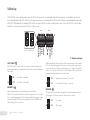
1300 USER MANUAL REV 1.0.0
FLARE IGNITION SYSTEM
WARNINGS
HW & FW VERSIONING
WARNING: EXPLOSION HAZARD
DO NOT INSTALL ON ENCLOSED BURNERS OR FIRE TUBES
This version of the manual was written for use with PF1300F
systems that have the following hardware and firmware versions.
DO NOT DISCONNECT WHILE CIRCUIT IS LIVE UNLESS AREA IS
KNOWN TO BE NON-HAZARDOUS
• HW • FW BATTERIES MUST ONLY BE CHANGED IN AN AREA KNOWN TO
BE NON-HAZARDOUS
SUBSTITUTION OF COMPONENTS MAY IMPAIR SUITABILITY
FOR CLASS 1, DIVISION 2
v2.3.0
v2.3.0
System hardware and firmware versions can be found printed
on separate labels inside of the enclosure on the circuit board.
(Section 2.4)
REPLACEMENT FUSES MUST BE CERAMIC
AVERTISSEMENT: RISQUE D’EXPLOSION
NE PAS INSTALLER DE BRÛLEURS FERMÉS OU TUBES
D’INCENDIE
NE PAS DEBRANCHERTANT QUE LE CIRCUIT EST SOUS
TENSION, A MOUNS QU’IL NE S’AGISSE D’UN EMPLACEMENT
NON DANGEREUX
BATTERIES NE DOIT ETRE CHANGÉ DANS UNE RÉGION CON
NUE COMME NON DANGEREUX
Please refer to the Profire Energy website for the latest
documentation.
APPROVALS
SC000 Class I, Div 2, Grp ABCD, T4A
CSA Type 4
SCB00 Class I, Div 2, Grp ABCD, T5
CSA Type 4
SUBSTITUTION DE COMPOSANTS PEUT PORTER ATTEINTE LES
QUALIFICATIONS POUR CLASSE 1, DIVISION 2
FUSIBLES DE REMPLACEMENT DOIVENT ÊTRE CÉRAMIQUES
MC#248705
FOR ANY QUESTIONS PLEASE CALL 1 855 PRO FIRE (1 855 776 3473) OR VISIT WWW.PROFIREENERGY.COM
1
Overview
1.1
1.2
1.3
1.4
1.5
1.6
1.7
2
Available Models
Included Components
Optional Components
External Diagram
Internal Diagram
Installation Types
Regulatory Requirements
Installation
1
3
4
5
6
7
8
8
9
2.1
Installation Warnings
2.2
Mounting Locations
2.3
Mounting Instructions
2.4
Circuit Board & Solar Charge Controller Diagram
2.5
Circuit Board Terminal Descriptions
2.6
Solar Charge Controller Terminal Descriptions
2.7
Required Wiring
2.7.1
SC000 System Wiring
2.7.2
SCB00 System Wiring
2.8
Optional Wiring
2.8.1
Status Contact
2.8.2
SC000 ESD Switch
2.8.3
SCB00 ESD Switch
12
13
14
15
16
17
17
18-19
20-21
22
22
23
24
3
User Interface & Settings
25
3.1
User Interface
3.1.1
Keypad Diagram
3.1.2
Keys
27
28
29
3.1.3
Indicator Lights
3.1.4
Debug LEDs
3.2
Settings
3.3
Operating the System
3.3.1
Starting the System
3.3.2
Stopping the System
3.3.3
LED Indicator Light Test
3.3.4
Viewing Firmware Versions
4
Modes & Behaviour
4.1
Mode Descriptions
4.2
State Diagrams
4.2.1
Manual Mode
4.2.2
On Demand Mode
4.2.3
Continuous Mode
4.2.4
Test Mode
4.3
Process Control Behaviour
4.3.1
Manual Mode
4.3.2
On Demand Mode
4.3.3
Continuous Mode
4.3.4
Test Mode
4.4
Timing Accuracy
5
Troubleshooting
30
31
32-33
34
34
35
36
37-38
5.1
5.2
53-54
55-56
Common Issues & Solutions
Flame Detection Troubleshooting Guide
Technical Specs
39
41
41
42
43
44
45
46
46
47
48
49
50
51
57
1 Overview
1 Overview
1
2
1 Overview
The PF1300F FIS (Flare Ignition System) is an electronic control and monitoring system designed for use with Flare Stacks. It’s purpose is to ensure that the flare is always lit, which facilitates compliance with the latest environmental regulations. This eliminates
the need to manually light the flare, providing convenience and improving operator safety. The system also includes a dry status
contact which enables remote monitoring of the flare status, reducing the number of times a person must physically visit a site.
1.1 Available Models
The PF1300F is available in two configurations:
BASE MODEL and BATTERY MODEL.
The Base model is designed for 12/24VDC operation whenever
power is available on site.
The Battery model includes a 12V/9Ah battery and solar charge
controller intended for use with a 12V solar panel (sold separately).
BASE MODEL
SC000 Base Model
BATTERY MODEL
SCB00 Battery Model
1 Overview
3
1.2 Included Components
The PF1300F comes packaged with the following. If any components (varies across models) are missing, contact Profire immediately.
B
INPUT:
SERIAL NO.
MC#248705
12V Nominal Solar Panel
40W MAX
12V. 9Ah, AGM
-40˚C - +50˚C
FLARE
IGNITION SYSTEM
Class I, Div 2, Grp ABCD; T5
Type 4
1PS13-SCB00
1300F
MODEL NO.
BATTERY:
AMBIENT:
1 855 PRO FIRE
1101-019-SCB00 Rev 2.0
ST
EM
NT
ER
S
at
er
p
O
LL
d
RO
R
E
V
A
an
CO
S
n
o
n
io
al
u
an
-1 0L
in
L-
V
an
M
4V
-2 4V
is
th
ed 12
12 2V
SS -2
• SS
• SS
•
ww
sa
18
ua
ea PA sta
Ph n, ing
ow rn
Ne w.
wt mo
8
M
l:
R
An
To
St i
Ga
r
A
INo
Np n US om
R r Ru 0 p.c
Oc o nt 94rcor
0L -2
ud
-6
-1 0L
cl
In SS SS -2
/
s
/ SS
/
el 2V V
od -1 -1 2V
0M -6
-1
er • SS -1 0L
M
av
I
AVERTISSEMENT: RISQUE D’EXPLOSION
NE PAS INSTALLER DE BRÛLEURS FERMÉS
OU TUBES D’INCENDIE
NE PAS UTILISER AVEC DES BLOCS D'ALIMENTATION
NE PAS DEBRANCHERTANT QUE LE CIRCUIT
EST SOUS TENSION, A
MOUNS QU’IL NE S’AGISSE D’UN EMPLACEMENT
NON DANGEREUX
AFIN D’ÉVITER TOUT RISQUE D’EXPLOSION,
S’ASSURER QUE L’EMPLACEMENT EST DÉSIGNÉ NON DANGEREUX AVANT
DE CHANGER LA BATTERIE
LA SUBSTITUTION DE COMPOSANTS PEUT
INACCEPTABLE POUR LES EMPLACEMENTSRENDRE CE MATÉRIEL
DE CLASSE I, DIVISION 2
SY
ti
N
U
la
PV
al
nS
Su
1 Overview
4
S
st
In
E
D
C
F
J
B
H
G
WARNING: EXPLOSION HAZARD
DO NOT INSTALL ON ENCLOSED BURNERS
OR FIRE TUBES
DO NOT USE WITH POWER SUPPLIES
DO NOT DISCONNECT WHILE CIRCUIT IS
LIVE UNLESS AREA IS KNOWN
TO BE NON-HAZARDOUS
BATTERIES MUST ONLY BE CHANGED IN
AN AREA KNOWN TO BE
NON-HAZARDOUS
SUBSTITUTION OF COMPONENTS MAY IMPAIR
SUITABILITY
FOR CLASS I, DIVISION 2
NLY
EL O
MOD
0
0
SCB
SC000
SCB00
DESCRIPTION
CODE
A
PF1300F
•
•
B
Mounting Brackets and Screws
•
•
C
90 Degree Bakelite Connector
•
•
D
Straight Silicone Boot
•
•
E
Brass Ferrule
•
•
F
Instruction Manual
•
•
G
12V/9Ah Battery (pre-installed)
•
H
Solar Charge Controller (pre-installed)
•
I
Solar Charge Controller Terminal Cover and Screws
•
J
Solar Charge Controller Manual
•
A
1.3 Optional Components
The following components may be required to install the PF1300F but are not included with the system. Profire offers some of
these components for sale individually and also in various kits.
Please contact Profire Sales for further information.
1.
MOUNTING HARDWARE
•
Channel Bar
•
Conduit Port
•
Liquid Tight Port
•
Rubber Grommet
2.
WIRE
•
Ignition Wire
3.
RODS AND CONNECTORS
•
Kanthal Ignition Rods (Various Lengths)
4.
PILOT ASSEMBLY
•
Nozzle
•
Brackets
5.
POWER & AUTONOMY
•
Power Supply
•
Solar Panel
1 Overview
5
1.4 External Diagram
DOOR & KEYPAD
1PS13-SCB00
1300F
MODEL NO.
BATTERY:
AMBIENT:
INPUT:
SERIAL NO.
MC#248705
12V Nominal Solar Panel
40W MAX
12V. 9Ah, AGM
-40˚C - +50˚C
FLARE
IGNITION SYSTEM
B
Class I, Div 2, Grp ABCD; T5
Type 4
DO NOT DISCONNECT WHILE CIRCUIT IS
LIVE UNLESS AREA IS KNOWN
TO BE NON-HAZARDOUS
BATTERIES MUST ONLY BE CHANGED IN
AN AREA KNOWN TO BE
NON-HAZARDOUS
SUBSTITUTION OF COMPONENTS MAY
IMPAIR SUITABILITY
FOR CLASS I, DIVISION 2
WARNING: EXPLOSION HAZARD
DO NOT INSTALL ON ENCLOSED BURNERS
OR FIRE TUBES
DO NOT USE WITH POWER SUPPLIES
1 855 PRO FIRE
1101-019-SCB00 Rev 2.0
1 Overview
6
SERIAL / MODEL LABEL
AVERTISSEMENT: RISQUE D’EXPLOSION
NE PAS INSTALLER DE BRÛLEURS FERMÉS
OU TUBES D’INCENDIE
NE PAS UTILISER AVEC DES BLOCS D'ALIMENTATION
NE PAS DEBRANCHERTANT QUE LE CIRCUIT
EST SOUS TENSION, A
MOUNS QU’IL NE S’AGISSE D’UN EMPLACEMENT
NON DANGEREUX
AFIN D’ÉVITER TOUT RISQUE D’EXPLOSION,
S’ASSURER QUE L’EMPLACEMENT EST DÉSIGNÉ NON DANGEREUX AVANT
DE CHANGER LA BATTERIE
LA SUBSTITUTION DE COMPOSANTS PEUT
INACCEPTABLE POUR LES EMPLACEMENTSRENDRE CE MATÉRIEL
DE CLASSE I, DIVISION 2
ENCLOSURE
E
S
U
F
E
R
A
P
S
E
S
U
F
X
1
2
S
CT
X
X
X
X
-X
X
X .0
X .3
X X
X -2 X
X XX X
X XX
ON
3
4
ON
1
S
1
2
CT
S
3
ON
OF
F
SOLAR CHARGE CONTROLLER
4
ors
50-7
4%
25-4
9%
Time
Flam
out
e Circ
uit
W .0
F .3
2
v
(AL
L OFF
)
Fla DE
BU
me
75-9 100%
9%
FA
UL
T
FLAM
E
219
232
Start
Auto Intensityrval t
Inte eou
Tim
G LE
Err Ds
1-24
%
0%
v2.3
PF
1300
219
232
1 0
Mode able d
En
LED Unuse
SP
AR
K
1
S
1PS13-SCB00
1300F
MODEL NO.
BATTERY:
AMBIENT:
INPUT:
SERIAL NO.
MC#248705
12V Nominal Solar Panel
40W MAX
12V. 9Ah, AGM
-40˚C - +50˚C
FLARE
IGNITION SYSTEM
B
Class I, Div 2, Grp ABCD; T5
Type 4
OF COMPONENTS MAY IMPAIR SUITABILITY
FOR CLASS I, DIVISION 2
WARNING: EXPLOSION HAZARD
DO NOT INSTALL ON ENCLOSED BURNERS
OR FIRE TUBES
DO NOT USE WITH POWER SUPPLIES
DO NOT DISCONNECT WHILE CIRCUIT IS
LIVE UNLESS AREA IS KNOWN
TO BE NON-HAZARDOUS
BATTERIES MUST ONLY BE CHANGED IN
AN AREA KNOWN TO BE
NON-HAZARDOUS
SUBSTITUTION
1 855 PRO FIRE
1101-019-SCB00 Rev 2.0
AVERTISSEMENT: RISQUE D’EXPLOSION
NE PAS INSTALLER DE BRÛLEURS FERMÉS
OU TUBES D’INCENDIE
NE PAS UTILISER AVEC DES BLOCS D'ALIMENTATION
NE PAS DEBRANCHERTANT QUE LE CIRCUIT
EST SOUS TENSION, A
MOUNS QU’IL NE S’AGISSE D’UN EMPLACEMENT
NON DANGEREUX
AFIN D’ÉVITER TOUT RISQUE D’EXPLOSION,
S’ASSURER QUE L’EMPLACEMENT EST DÉSIGNÉ NON DANGEREUX AVANT
DE CHANGER LA BATTERIE
LA SUBSTITUTION DE COMPOSANTS PEUT
INACCEPTABLE POUR LES EMPLACEMENTSRENDRE CE MATÉRIEL
DE CLASSE I, DIVISION 2
BATTERY
A
4
BATTERY BRACKET
CIRCUIT BOARD
F1
F2
(SCB00 ONLY)
R
ES
ET
1.5 Internal Diagram
WIRING DIAGRAM
DIP SWITCH DIAGRAM
PLUGGABLE HEADER
IGNITION COIL
KEYPAD FLEX CABLE
(SCB00 ONLY)
7
1 Overview
1.6 Installation Types
The PF1300F is designed for use only on Flare stacks. It should not be used to control an enclosed burner or fire tube as this is usually against code and would pose a safety risk.
1.7 Regulatory Requirements
The PF1300F is certified for use in Class I, Division 2, Group ABCD locations. Certain modes of operation or wiring options may be
against code in some locations.
Profire makes no assertion as to the suitability of a particular component for a given application. It is up to the customer to examine
the local codes and safety requirements to determine if the PF1300F and any other associated components sold by Profire are suitable for use in a given application.
NORTH AMERICA
The PF1300F is certified for use in Canada, USA, and Mexico.
OTHER
Consult local codes and safety regulations to determine if the
PF1300F can be used in your jurisdiction.
8
1 Overview
2 Installation
This section includes the steps that should typically be followed when installing a PF1300F system in the field. If you are new to the
PF1300F, you should read this section in its entirety and follow these instructions closely.
STEPS
1.
Review Installation Warnings
2.
Choose a Mounting Location
3.
Mount the System
4.
Get Familiar with the Circuit Board
5.
Connect the Required Wiring including Power, and Ignition
Coil / Flame Detection wiring
6.
Connect the optional wiring including the Status Contact
and the ESD switch.
The steps provided here are general and will help you to identify questions that need to be answered to complete the installation
properly. You should also consult your local electrical and gas code before attempting any installation.
2 Installation
11
2.1 Installation Warnings
Before installing the PF1300F, please review the following list of warnings. Failure to observe these may result in death, electrocution, property damage, product damage, and/or government fines.
ALL MODELS
BATTERY MODELS
1.
The PF1300F is NOT intended for use on enclosed burners or
fire tubes as it may pose a safety risk and may be against code in
some jurisdictions. For these applications, please consider using
our PF2100 system.
6.
2.
The PF1300F is NOT designed to control a pilot or main solenoid.
The PF1300F is NOT CSA B149 compliant. If you require automatic electronic control of a valve train, please consider using our
PF2100 system.
Never store or ship the unit with the battery connected. Disconnect the battery’s negative wire from the charge controller
and cover the fork connector with electrical tape or some other
insulator that will prevent it from shorting to other components.
Failure to observe this warning may result in accidental electrocution, fire, product damage, or simply a dead battery.
7.
Never operate the unit with the zener diode removed from
across the load terminals of the charge controller as this may
lead to failure.
8.
Never power these from any DC power supply or from a solar
panel rated for more than 12V nominal (40W). This may lead to
failure of the charge controller.
9.
Be careful not to damage the temperature sensor on the charge
controller. It is delicate and if damaged, the charge controller will
not function.
3.
4.
5.
12
Failure to properly ground the pilot assembly back to the
PF1300F’s EGND screw may result in accidental electrocution,
product damage, or simply failure to ignite the pilot.
The PF1300F generates 20kV - 40kV at its high voltage output
terminal which can cause burns or cardiac arrest. Do not touch
or place any object near the ignition coil’s high voltage terminal or
connected ignition wire while the product is operating.
Even without making physical contact with the terminal, it is possible to draw a spark from several inches away, especially if the
pilot bracket is not properly grounded.
Never leave the PF1300F running unattended without the door
screws securely tightened down. This is to prevent moisture
from penetrating inside of the enclosure and damaging the
product. Moisture damage to the internal circuitry is not covered
by the product warranty if the door has been left open.
2 Installation
2.2 Mounting Locations
The PF1300F should be mounted at the base of the Flare Stack or in another location that is both safe and easily accessible.
The recommended mounting height is 1.5m (5ft) above the ground or platform that the operator will be standing on.
Please consider the following when choosing an install location:
1.
2.
3.
4.
ACCESSIBILITY
The operator should be able to easily access the system to
observe its operation and to adjust settings. The system should
not be mounted facing the sun to make it easier to observe the
LED indicators on the front panel.
SECURITY
In some situations, it may be desirable to mount the system in
a location that is not accessible to the general public to prevent
accidental and intentional tampering.
OPERATOR SAFETY
The system should not be mounted in a dangerous location such
as close to the top of the flare stack where an operator might be
placed in undue danger.
PERFORMANCE
Choose a mounting location that will allow ground and
ignition wires to be kept as short as possible. This will ensure
the best ignition and flame detection.
5.
PRODUCT PROTECTION
To protect the system from being damaged, it should not
be mounted:
a.
Where chemicals may splatter or bubble over from
the flare onto the system. Chemicals on the keypad
may interfere with an operator’s ability to control
the product or view the LED indicators.
b.
Near the top of the flare where excessive heat may
damage the product. Refer to the maximum
operating temperature listed in this document.
c.
To anything that may tip over due to wind or snow.
For example, a pole that is not set properly into the
ground or a tripod that is not secured with anchor
bolts or guy wires.
In locations that may be prone to flooding.
d.
2 Installation
13
2.3 Mounting Instructions
1.
Remove and open the included bag of components taped to
the mounting brackets.
2.
Attach the two mounting brackets to the back of the PF1300F
enclosure using the 4 screws.
3.
Determine the best location to drill holes in the product
enclosure for the wires to enter. At least two holes are
recommended for the following:
• Wiring that will go to the pilot assembly
• Wiring that will go to the power source
and status contacts.
It is recommended that these holes be drilled on the
bottom of the enclosure (as shown).
4.
Install grommets or conduit ports as required.
5.
Securely mount the enclosure to either a pole, structure,
or building which satisfies the location requirements
previously listed in section 2.2 (Mounting Locations).
POWER SOURCE
SOLAR PANEL
REMOTE MONITORING
DETERMINE DRILL LOCATIONS
PILOT ASSEMBLY
14
2 Installation
2.4 Circuit Board & Solar Charge Controller Diagram
PLUGGABLE HEADER
SPARK LED
FLAME LED
+
ION TERMINALS
+
SPARK
+
ON
Ion
ON BUTTON
DEBUG LEDs
Flame
Errors
100%
S1
50-74%
Timeout
25-49%
3
4
F2
Auto Start
Intensity
Interval
Timeout
2
DIP SWITCHES
1-24%
CTS
0%
232
219
232
1
SPARE FUSE
ON
1
2
3
4
FW
v2.3.0
1
0
LED Enable
Unused
F1
219
CTS
Mode
ON
OFF BUTTON
DEBUG LEDs
75-99%
S1
4A FUSE
SOLAR INPUT
FAULT
OFF
XXXXXX-XXXXX
XXX-2.3.0
XXXXXX
VBatt
HW VERSION
TEMPERATURE SENSOR
FLAME
Coil
1
2
3
VBATT TERMINALS
Status
Flame Circuit
(ALL OFF)
RESET
+
6
5
4
-
COIL TERMINALS
FUSES
FAULT LED
PF1300 v2.3
STATUS TERMINALS
RESET BUTTON
FW VERSION
SUNSAVER-6
SOLAR CONTROLLER SS-6-12V
SOLAR
+
BATTERY
-
+
LOAD
-
+
-
SEALED
OR
FLOOD
SELECT
BATTERY TYPE SELECT
JUMPER
BATTERY I/O
LOAD OUTPUT
Solar Charge Controller only included with SCB00 model
2 Installation
15
2.5 Circuit Board Terminal Descriptions
This table provides a brief description of each terminal and references to further detail.
TERMINAL
EXPECTED CONNECTIONS
DESCRIPTION
SECTION
Status -
Connect to PLC negative input contact or other alarm device.
2.8.1
Status +
Connect to PLC positive input contact or other alarm device.
This is a dry contact output used to indicate system status to an external device (eg. a PLC). The contacts will be closed when the system
is running and opened when the system is shutdown. Note that the
contacts are not internally connected to power or ground.
200V (Peak AC or DC), 150mA, 5Ω
Coil -
Ground return for the ignition coil.
Connect to ignition coil primary black
wire.
Coil +
Driver for the low voltage primary of
the ignition coil. Connect to ignition
coil primary red wire.
Ion -
Flame Detection negative input.
Connect to ground screw on the
PF1300F and also to the ground
screw on the pilot assembly.
Ion +
Flame Detection positive input.
Connect to ignition coil’s left high
voltage terminal.
VBatt -
Ground back to DC source
VBatt +
Input power from a DC source
The primary of the ignition coil should be connected to these terminals.
DC pulses will be applied while sparking. This output is protected by a
250mA thermal fuse.
These terminals are used for flame detection. Place a Kanthal rod
2.7.1, 2.7.2
directly in the pilot flame and connect it to the ignition coil’s right high
voltage terminal. The PF1300F will apply a 65VAC signal to the flame
rod. These inputs are protected from high voltage allowing them to be
connected in series with the high voltage terminals of the ignition coil.
This enables a single flame rod to be used for both ignition and flame
detection. The pilot assembly must be grounded for the flame detection
to function properly.
These terminals are used to power the system. Apply input power in
the range of 12 - 24VDC, 4A MAX. Should connect to the solar charge
controller’s load output terminals on the SCB00 model.
This input is protected by a 4A fuse.
16
2 Installation
2.7.1, 2.7.2
2.7.1, 2.7.2
2.6 Solar Charge Controller Terminal Descriptions
This table provides a brief description of each terminal and references to further detail. This is only applicable to the SCB00 model.
TERMINAL
EXPECTED CONNECTIONS
DESCRIPTION
SECTION
Solar +
12V Solar Panel positive terminal
Only a 12V nominal Solar Panel (40W MAX) should be used.
2.7.2
Solar -
12V Solar Panel negative terminal
Battery +
Battery positive terminal
Battery negative terminal
These terminals are used to draw power from and to charge the integrated battery.
2.7.2
Battery Load +
Circuit Board VBatt positive terminal
2.7.2
Load -
Circuit Board VBatt negative terminal
These terminals are used to supply power to the PF1300F circuit board.
A protection diode must also be installed across these terminals to
protect the controller from back EMF from the load.
Sealed or
Flooded Select
Jumper to load negative terminal
This jumper is used to select the battery type and should always be
installed because the included battery is sealed.
2.7.2
2.7 Required Wiring
The wiring in this section of the document is required for all PF1300F installations. Skipping or performing any steps in this section
incorrectly will likely result in the PF1300F not functioning properly.
Choose the wiring steps that apply to your model.
2 Installation
17
2.7.1 SC000 System Wiring
This wiring diagram can also be found printed on the inside of the PF1300F door panel (SC000).
18
2 Installation
2.7.1 SC000 System Wiring Continued...
These instructions detail the correct wiring of a PF1300F base model.
Use 16 AWG or larger diameter wire for all connections unless otherwise noted.
1.
Feed the 7mm diameter ignition wire through the grommet and
into the PF1300F enclosure.
2.
Attach the included 90 degree bakelite connector to the end of
the ignition wire that is inside of the enclosure.
3.
Connect the bakelite connector to the right terminal of the ignition coil.
4.
Slide a straight silicone boot over the other end of the ignition
wire and then connect the ferrule to it.
5.
Attach the ferrule to the Kanthal ignition/flame detection rod.
6.
Slide the silicone boot over the ferrule.
7.
Feed two ground wires up through the grommet next to the
ignition wire.
8.
Crimp fork connectors to both ground wires and attach them to
the EGND screw below the ignition coil.
9.
Outside of the enclosure, connect one ground wire to the pilot
assembly and the other to earth ground.
10.
Feed a pair of power wires into the enclosure through the
conduit port and attach them to the VBatt + and - terminals
on the pluggable header.
11.
Outside of the enclosure, attach the power wires to a 12VDC or
24VDC power source. For more info, see the technical specifications at the back of this document.
2 Installation
19
2.7.2 SCB00 System Wiring
This wiring diagram can also be found printed on the inside of the PF1300F door panel (SCB00).
TVS Zener Diode
20
2 Installation
2.7.2 SCB00 System Wiring Continued...
These instructions detail the correct wiring of a PF1300F system with an integrated battery and solar charge controller.
Use 16 AWG or larger diameter wire for all connections unless otherwise noted.
1.
Feed the 7mm diameter ignition wire through the grommet and
into the PF1300F enclosure.
2.
Attach the included 90 degree bakelite connector to the end of
the ignition wire that is inside of the enclosure.
3.
Connect the bakelite connector to the right terminal of the ignition
coil.
4.
Slide a straight silicone boot over the other end of the ignition
wire and then connect the ferrule to it.
5.
Attach the ferrule to the Kanthal ignition/flame detection rod.
6.
Slide the silicone boot over the ferrule.
7.
Feed two ground wires up through the grommet next to the
ignition wire.
8.
Crimp fork connectors to both ground wires and attach them to
the EGND screw below the ignition coil.
9.
Outside of the enclosure, connect one ground wire to the pilot
assembly and the other to earth ground.
10.
Feed a pair of power wires into the enclosure through the conduit port and attach them to the Solar + and - terminals on the
solar charge controller.
11.
Outside of the enclosure, attach the power wires to a 12V (40W
Max) solar panel. Note that the charge controller is not designed
to be used with DC power supplies or with solar panels larger
than 12V nominal.
12.
Locate the black wire attached to the negative terminal of the
battery and remove the insulating cover from the fork connector.
It is taped to the top of the solar charge controller at the factory.
13.
Attach the negative battery wire to the Battery- terminal on the
solar charge controller.
2 Installation
21
2.8 Optional Wiring
The wiring in this section of the document is optional. This includes the status contact and ESD switch. Note that the wiring of the
ESD switch differs depending on model.
2.8.1 Status Contact
The status contact is a solid state relay wired as a dry contact which means that it does not source any power. A maximum of 200V
(Peak AC or DC) at 150mA can be run through the contact safely.
The status contact can be used to control a remote alarm. The status contact is initially open when the system is unpowered or not
running. When the system is running, the behavior of the contact varies depending on the mode selected. In general, it is closed
when flame is detected and open after flame has been absent for the duration of the timeout. For detailed behaviour, refer to the
charts in section 4.3.
To wire the status contact, follow these steps:
EXAMPLE 2: DC LOAD ON POSITIVE TERMINAL
1.
Feed a pair of wires in through the conduit port and connect
them to the Status + and - terminals on the pluggable header.
2.
Outside of the enclosure, connect the status wires to a PLC or
an alarm as shown in one of the examples below.
12 to 200VDC
Alarm
Device
PF1300 v2.
+
+
-
EXAMPLE 3: AC
-
1
2
3
4
0%
1
2
3
4
FW
232
CTS
219
232
4
1
2
3
PF1300 v2.
4
1
0
LED Enable
Unused
3
SPARK
ON
Ion
XXXXXX-XXXXX
XXX-2.3.0
XXXXXX
VBatt
S1
Flame Circuit
S1
(ALL OFF)
ON
4A FUSE
FLAME
Mode
Coil
Timeout
1-24%
CTS
232
ON
2
Auto Start
Intensity
Interval
Timeout
F2
+
50-74%
219
219
CTS
232
ON
4A FUSE
1
CTS
ON
CTS
232
S1
25-49%
F1
+
Errors
100%
S1
219
F1
Flame
+
75-99%
2 Installation
-
ON
219
VBatt
OFF
DEBUG LEDs
XXXXXX-XXXXX
XXX-2.3.0
XXXXXX
CTS
232
+
4A FUSE
219
ON
Ion
Alarm
Device
OF
S1
ON
Status
SPARE FUSE
+
Coil
1
2
3
-
FAULT
VBatt
1
2
3
+
FLAME
1
+
SPARK
ET
Alarm
Device
Status
6
5
4
+
FLAME
XXXXXX-XXXXX
XXX-2.3.0
XXXXXX
S1
~
PF1300 v2.3
22
+
120VAC
12 to 200VDC
ON
Ion
6
5
4
EXAMPLE 1: DC LOAD ON NEGATIVE TERMINAL
SPARK
Coil
1
2
3
+
Status
6
5
4
-
OF
2.8.2 SC000 ESD Switch
If desired, an Emergency Shutdown Switch can be attached to the PF1300F. The wiring for this switch will vary
slightly depending on model.
These instructions describe how to correctly wire an ESD switch to a PF1300F model SC000.
1.
Cut the negative power wire outside of the enclosure and install
an ESD (Emergency Shutdown) switch.
Note that if it is desired to connect the PF1300F to a plant ESD
loop, a relay must be used.
Optional
2 Installation
23
2.8.3 SCB00 ESD Switch
These instructions describe how to correctly wire an ESD switch to a PF1300F model SCB00.
1.
Remove the wire connected between the solar charge controller’s Load- terminal and the VBatt- terminal of the pluggable
header.
2.
Ensure that the zener diode remains connected across the load
+ / - terminals of the solar charge controller.
3.
Run two more wires into the enclosure through the conduit port.
4.
Attach one of the new wires to the VBatt- terminal of the pluggable header and the other to the Load- wire of the solar charge
controller.
5.
Outside the enclosure, attach the ESD wires to an ESD switch.
Note that if it is desired to connect the PF1300F to a plant ESD
loop, a relay must be used.
TVS Zener Diode
24
2 Installation
3 User Interface & Settings
This section of the manual is organized into three sub-sections. The first deals with the user interface. The next sub-section contains
detailed information about the settings that can be adjusted. The final sub-section contains instructions on how to operate the system.
3.1 User Interface
The user interface consists of three parts:
1.
A Keypad
2.
Indicator lights
3.
DIP Switches
The following sub-sections describe each of these in detail.
3 User Interface & Settings
27
3.1.1 Keypad Diagram
SPARK LIGHT
FLAME LIGHT
4
ON KEY
28
3 User Interface & Settings
FAULT LIGHT
OFF KEY
3.1.2 Keys
There are two keys on the keypad that are used to operate the
PF1300F:
• ON
• OFF
1300
For convenience during installation and debugging, these keys
are also duplicated on the circuit board inside of the enclosure.
ON KEY
1
The ON key is used to start or restart the system.
1
2
OFF KEY 2
The OFF key is used to stop the system.
PF1300 v2.3
-
Ion
XXXXXX-XXXXX
XXX-2.3.0
XXXXXX
1
2
3
+
SPARK
+
FAULT
FLAME
Coil
VBatt
ON
OFF
1
2
DEBUG LEDs
Flame
Errors
100%
75-99%
S1
S1
50-74%
Timeout
25-49%
3
4
Auto Start
Intensity
Interval
Timeout
2
1-24%
0%
232
CTS
219
232
ON
1
2
3
4
1
0
LED Enable
Unused
219
F1
1
SPARE FUSE
F2
CTS
FW
v2.3.0
Flame Circuit
(ALL OFF)
Mode
ON
4A FUSE
RESET
+
Status
6
5
4
+
3 User Interface & Settings
29
3.1.3 Indicator Lights
There are three indicator lights on the keypad that are used to
show the status of the PF1300F.
• SPARK
• FLAME
• FAULT
1300
For convenience during installation and debugging, these LEDs
are also duplicated on the circuit board inside of the enclosure.
These duplicate LEDs are disabled by default to conserve power.
1
2
3
To turn them on, use the “LED Enable” DIP switch.
SPARK LED 1
The Spark LED will pulse approximately once per second to indicate
that the system is running. When the system is sparking, the Spark
LED will pulse rapidly.
FLAME LED 2
1
+
-
-
3
SPARK
ON
Ion
30
3 User Interface & Settings
VBatt
FLAME
FAULT
OFF
Flame
Errors
100%
75-99%
S1
50-74%
Timeout
25-49%
SPARE FUSE
4
1-24%
0%
232
CTS
219
ON
232
3
1
2
3
4
1
0
LED Enable
Unused
219
CTS
2
Auto Start
Intensity
Interval
Timeout
1
Mode
ON
4A FUSE
F1
The Fault LED will turn on when the flame has been continuously
absent for the entire timeout period. It will also turn on if
a problem with the flame detection circuit is discovered.
3
DEBUG LEDs
XXXXXX-XXXXX
XXX-2.3.0
XXXXXX
S1
F2
FAULT LED
+
2
PF1300 v2.3
Coil
1
2
3
+
Status
FW
v2.3.0
Flame Circuit
(ALL OFF)
RESET
+
6
5
4
The Flame LED will turn on when the system has detected that flame
is present. In the normal operating modes, the Flame LED is time
averaged over a few seconds to prevent the LED from flickering when
wind is present. In the test mode, the Flame LED is not averaged.
3.1.4 Debug LEDs
The debug LEDs are located on the circuit board (inside the enclosure). They only function when the “LED Enable” DIP switch
1 is in the ON position. This is done to conserve power when they are not needed.
S1
FLAME QUALITY 2
5 LEDs on
4 LEDs on
3 LEDs on
2 LEDs on
1 LED on
No LEDs on
= 100%
= 75-99%
= 50-74%
= 25-49%
= 1-24%
= 0%
1
ERROR 3
When the PF1300F is in the Fault state, the Debug LEDs will
show the reason for the fault using one of the error LEDs. The
reasons are listed below.
Timeout 4
The flame went out and could not be relit before the timeout
expired.
Flame Circuit 5
The system detected a problem with the flame detection circuit.
This usually indicates a faulty circuit board.
2
3
4
1
2
3
4
1
0
LED Enable
Unused
•
•
•
•
•
•
1
Auto Start
Intensity
Interval
Timeout
When the PF1300F is on and running, the Debug LEDs will show
the flame quality as a bar graph. The more LEDs lit, the better
the quality. The Flame LEDs on the keypad and the circuit board
will both turn on when the quality is above 50% (3 bars or more).
S2
Mode
• When the system is off, the Debug LEDs will be too.
• When the system is on, the Debug LEDs are used to indicate one of two things listed below:
• Flame Quality
• Error
DEBUG LEDs
2
Flame
Errors 3
100%
75-99%
50-74%
Timeout
25-49%
1-24%
0%
4
Flame Circuit
5
(ALL OFF)
3 User Interface & Settings
31
3.2 Settings
The PF1300F can be configured by using the DIP switches on the circuit board inside of the enclosure. Listed below are the features configured by these DIP switches. For your convenience, a summary of the DIP switch settings is also provided on the inside
of the PF1300F door panel. Changing DIP switch settings while the system is running may cause it to enter the OFF state. Simply
restart the system by pressing the ON key if this occurs.
S1
S2
S1
2
3
4
1
1
0
LED Enable
Unused
Mode
1
2
3
4
*
ON OFF 1
0
D Enable
Unused
uto Start
Intensity
Interval
Timeout
OFF Low Intensity (Power), 1 second
INTERVAL 3
S2
The Interval is the time between ignition attempts when running in
On Demand or Continuous mode. There are two options:
Mode
Auto Start
Intensity
Interval
Timeout
1
0
LED Enable
Unused
S2
Mode
Mode
1
Mode
0 10
LED Enable
LED Enable
Unused
Unused
Intensity
Interval
Timeout
1
0
LED Enable
Auto Start
Unused
Intensity
Interval
Auto Start
Timeout
Auto Start
Intensity
Interval
Timeout
Mode
4
4
S2
3
Default setting(s)
High Intensity (Power), 2 seconds
5 seconds
10 seconds
S1
S1
3 User Interface & Settings
2
3
4
4
3
2
With low intensity selected, the system will generate a cooler spark
for 1 second during ignition. This mode provides the lowest possible
power consumption. This mode is preferred for the SCB00 model
where battery life is a concern.
2
*
3
S1
1
2
4
1
3
4
1
Spark intensity can be selected between low and high.
1
32
2
ON 3
1
*
Auto Start
Intensity
Interval
Timeout
Interval
Timeout
1
Mode
0
LED Enable
Unused
INTENSITY 2
4
2
Auto Start is disabled
4
3
1
4
OFF 3
4
Auto Start is enabled
2
*
3
3
With high intensity selected, the system will generate a hotter spark
for 2 seconds during ignition. This mode can be used if the pilot gas
is wet, the flame rod is dirty, the spark gap is too large, or the ignition
S2
wire is too long. This mode is not recommended on 24V systems as it
may prematurely wear the circuit components.
1
1
ON 2
Auto Start
Intensity
Interval
Timeout
Auto Start
Intensity
Interval
Timeout
4
2
2
*
1
Mode
0
LED Enable
Unused
1
Mode
0
LED Enable
Unused
If this DIP switch is set to ON, the system will automatically start
S2
running when power is applied. Auto Start will not work in S1
Manual or
Test mode.
S1
1
8
S2
OFF
1
4
7
S1
ON
3
6
4
3 1 4 2
SWITCH ORIENTATION
AUTO START 1
3
2
5
3
1
4
2
4
3
1
3
2
4
2
1
3
1
S2
2
S2
1
S1
4
1
0
LED Enable
Unused
Auto Start
Intensity
Interval
Timeout
Mode
Auto Start
Auto
Start
Intensity
Intensity
Interval
Interval
Timeout
Timeout
1
Mode
1
0
Mode
0
LED Enable
LEDUnused
Enable
Unused
1
0
LED Enable
Unused
ON OFF S2
Mode
Mode
1
0
LED Enable
Unused
4
Unused
Unused
S1
4
3
2
*
3
1
2
4
1
3
Auto Start
Intensity
Interval
Timeout
Keypad LEDs enabled
2
12
23
34
4
1
12
S1 S1
1
Auto Start
Intensity
Interval
Timeout
OFF Circuit Board + Keypad LEDs enabled
UNUSED 8
S2
This switch is ignored by the current firmware version and should be
left in the OFF position
23
34
4
2
3
S2 S2
4
1
2
3
4
1
2
3
4
The
system will spark periodically whenever flame is not detected. It will stop sparking after the
selected timeout expires.
S1
1
Mode
0
LED Enable
Unused
ON 1
1
S2
Intensity
Interval
Timeout
4
S2
4
*
3
S1
3
4
2
2
3
S2
4
1
1
2
4
3
2
3
4
The system will only spark while the ON
S1
S2
button is being held down.
This mode will NOT automatically relight the flare.
OFF, ON On Demand Mode
S1
2
3
1
Mode
0
LED Enable
Unused
OFF, OFF Manual Mode
2
1
1
The selectable modes are:
4
4
S1
The LEDs on the keypad are always enabled, regardless of this setting.
Further detail on these modes can be found in section 4.
3
3
1
0
LED Enable
Unused
When this switch is set ON, the LEDs on the circuit board inside the
PF1300F enclosure will be enabled. This includes the Spark, Flame,
S2 and Debug LEDs.
Fault,
There are three operational modes and one test mode that can be
S1
selected using the DIP switches. This is the only setting that requires
two DIP switches to adjust.
1
7
Auto Start
Intensity
Interval
Timeout
Auto Start
Auto
Start
Auto Start
Intensity
Intensity
Intensity
Interval
Interval
Interval
Timeout
Timeout
Timeout
1
Mode
1
1
0
Mode
Mode
0
0
LED Enable
LEDUnused
Enable LED Enable
Unused
Unused
Mode
LED ENABLE
6
2
2
5 minutes
*
ON ON Test Mode
12
23
34
4
Similar
to the manual mode except that after
the ON button is released, the system will
enter a continuous flame detection mode
which is useful for debugging the flame
detection circuit wiring.
1
60 minutes
1
Interval
Timeout
1
Auto Start
Intensity
Interval
Timeout
MODE
4
1
Mode
0
LED Enable
Unused
5
S2
OFF ON, OFF Continuous Mode
2
3
4
The system will spark periodically regardless of
whether flame is being detected.
S1
ON 3
4
2
3
34
1
23
4
2
*
Auto Start
Intensity
Interval
Timeout
1
12
• In On Demand and Continuous mode, the timeout is user
selectable between 5 minutes and 60 minutes
4
1
3
1
Mode
0
LED Enable
Unused
S2
1
S2 S2
The
status contacts will open after the
selected timeout expires but the system
will not stop running and sparking.
• In Manual and Test mode, the timeout DIP switch is ignored.
The setting is fixed at 5 seconds and 0 seconds respectively.
3
4
S1 S1
• In Manual and On Demand mode, the system will stop
running when the timeout expires.
S1
3
2
The timeout determines when the fault LED will turn on and the status contacts will open. The behaviour varies between modes:
2
1
S2
TIMEOUT 4
1
Auto Start
Intensity
Interval
Timeout
1
Mode
0
ED Enable
Unused
S1
3 User Interface & Settings
33
3.3 Operating the System
This section of the manual describes how to operate the system including how to start and stop it in various ways, test the LEDs,
and how to check the system firmware version.
3.3.1 Starting the System
If there is an external ESD switch installed on the system, it must be
turned on so that power will be applied to the PF1300F.
If the Auto Start DIP switch is set to the OFF position, when power is
first applied to the PF1300F it will enter the low power OFF state. In
this state all LEDs are off.
1300
Press one of the On keys to start the system running.
There are two On keys which perform the same function: 1 Keypad (outside of enclosure)
2 Circuit Board (inside of enclosure)
1
If the Auto Start DIP switch is set to the ON position, (On Demand
or Contiuous Mode only) the system will begin running immediately
without the need to press one of the On keys.
PF1300 v2.3
+
+
+
ON
Ion
2
XXXXXX-XXXXX
XXX-2.3.0
XXXXXX
VBatt
FAULT
OFF
DEBUG LEDs
Flame
Errors
100%
75-99%
S1
S1
50-74%
Timeout
25-49%
3
4
Auto Start
Intensity
Interval
Timeout
2
1-24%
0%
232
CTS
219
ON
232
CTS
219
F1
1
1
2
3
4
1
Mode
0
LED Enable
Unused
ON
4A FUSE
F2
3 User Interface & Settings
FLAME
Coil
SPARE FUSE
34
SPARK
1
2
3
Pressing the On key while the system is already running will cause
the system to restart. When it restarts, it will immediately begin to
spark. The timout counter will also be reset.
Status
FW
v2.3.0
Flame Circuit
(ALL OFF)
RESET
+
6
5
4
-
If the system is stopped with the Fault LED on, pressing either On
key will cause the system to restart.
3.3.2 Stopping the System
If there is an external ESD switch installed on the system, it can be
used to stop the system by cutting its power.
There are two Off keys which perform the same function: 1 Keypad (outside of enclosure)
2 Circuit Board (inside of enclosure)
1300
Pressing one of the Off keys will also stop the system. When an Off
key is pressed, all LEDs will turn off and the system will enter a low
power state. This is true whether the system was previously running
or stopped with the Fault LED on.
1
PF1300 v2.3
+
-
+
FAULT
FLAME
Coil
ON
Ion
VBatt
OFF
2
XXXXXX-XXXXX
XXX-2.3.0
XXXXXX
1
2
3
+
SPARK
DEBUG LEDs
Flame
Errors
100%
75-99%
S1
S1
50-74%
Timeout
25-49%
3
4
1-24%
0%
232
CTS
219
ON
232
2
Auto Start
Intensity
Interval
Timeout
SPARE FUSE
F2
CTS
219
F1
1
1
2
3
4
1
Mode
0
LED Enable
Unused
ON
4A FUSE
FW
v2.3.0
Flame Circuit
(ALL OFF)
RESET
-
Status
6
5
4
+
3 User Interface & Settings
35
3.3.3 LED Indicator Light Test
If you become concerned that one of the LED indicator lights
on the keypad or circuit board is no longer functioning, you can
verify if this is the case by following this procedure. Note that
this will turn the system off momentarily and the status contacts will open.
2.
Press and release the reset button 1 on the circuit board
3.
All LEDs on the circuit board will flash briefly in the following
sequence: Debug LEDs (D20, D21, D22, D23, D24), Spark,
Flame, Fault
4.
Press and release the reset button 1 on the circuit board again
PF1300 v2.3
-
5.
Quickly close the door and observe the keypad
6.
All LEDs on the keypad will flash briefly in the following sequence: Spark, Flame, Fault
+
+
-
SPARK
+
FLAME
FAULT
Coil
ON
Ion
VBatt
OFF
DEBUG LEDs
XXXXXX-XXXXX
XXX-2.3.0
XXXXXX
1
2
3
+
Status
Flame
Errors
100%
75-99%
S1
S1
50-74%
Timeout
25-49%
36
3 User Interface & Settings
3
4
Auto Start
Intensity
Interval
Timeout
2
1-24%
0%
232
CTS
219
ON
232
CTS
219
F1
SPARE FUSE
F2
If an LED fails to flash on as described, or if more than one LED
turns on simultaneously, the keypad or circuit board may need
to be replaced.
1
1
2
3
Flame Circuit
(ALL OFF)
4
1
Mode
0
LED Enable
Unused
ON
4A FUSE
RESET
Set the “LED Enable” DIP Switch on the circuit board to the ON
position.
6
5
4
1.
1300
FW
v2.3.0
1
3.3.4 Viewing Firmware Versions
The firmware version is printed on a label 1 on the circuit
board. If this label is missing or illegible, the firmware version
can also be checked using the LEDs. The procedure to do this is
as follows. Note that this will turn the system off momentarily
and the status contact will open.
PF1300 v2.3
+
+
Status
SPARK
+
FAULT
FLAME
Coil
Ion
XXXXXX-XXXXX
XXX-2.3.0
XXXXXX
VBatt
ON
OFF
3
4
DEBUG LEDs
Flame
Errors
100%
75-99%
S1
S1
50-74%
Timeout
25-49%
1
SPARE FUSE
3
ON
4
1-24%
CTS
0%
232
CTS
2
219
ON
4A FUSE
1
2
3
Flame Circuit
(ALL OFF)
4
RESET
+
232
The LED’s on the circuit board will begin to blink a sequence of
patterns on the LED’s. When you are done determining the firmware version, let go of the buttons and the system will resume
normal operation.
1
Mode
0
LED Enable
Unused
4.
219
Release the reset button but continue to hold the On and Off
buttons.
Auto Start
Intensity
Interval
Timeout
3.
6
5
4
With your right hand press and hold the reset button 2 on the
circuit board. At the same time, use your left hand to also press
and hold the On 3 and the Off 4 buttons.
1
2
3
2.
F1
Set the LED Enable DIP Switch to the ON position.
F2
1.
1300
FW
v2.3.0
1
2
3 User Interface & Settings
37
3.3.4 Viewing Firmware Versions Continued...
PART AND DIGIT DECODING
FIRST PART
PART
Spark
SECOND PART
THIRD PART
ON
Flame
ON
Fault
ON
MODE
0
1
2
3
4
5
6
7
D23
DIGIT
The LED pattern can be decoded into a firmware version.
The digits are encoded in binary on the debug LED’s. The
Spark, Flame, and Fault LED’s are used to indicate which
part of the firmware version number is being shown. When
written out, the three parts are separated by periods (Eg:
2.3.0 where the first part is “2”, the second part is “3” and
the third part is “0”.) Note that multiple digits may be shown
per part. If this is the case, they will be separated by a brief
pause with all LED’s off.
D22
ON
D21
ON
D20
ON
ON
ON
ON
ON
ON
ON
ON
ON
8
9
ON
ON
ON
ON
EXAMPLE FIRMWARE VERSION DECODING
PART
This table shows how firmware version v2.3.0 would be encoded.
LED
PATTERN 1
Spark
ON
PATTERN 2
Flame
PATTERN 3
ON
Fault
ON
DIGIT
D23
D22
D21
ON
ON
D20
Firmware Version
38
3 User Interface & Settings
ON
2
.
3
.
0
4 Modes & Behaviour
4 Modes & Behaviour
39
40
4 Modes & Behaviour
This section of the manual describes the behaviour of the PF1300F when various features are enabled vs disabled. Simplified state
diagrams are provided and discussed to give a high level understanding of how the system works. Detailed behaviour descriptions
are also provided including process charts to illustrate the behaviour. These are provided for each of the four available modes. Note
that all timing is nominal and may vary across systems and with temperature.
4.1 Mode Descriptions
There are three operational modes and one test mode that can be selected using the DIP switches. The following chart describes
the differences between these modes.
FEATURE
MANUAL MODE
ON DEMAND MODE
CONTINUOUS MODE
TEST MODE
Auto Start
No
User Selectable (Yes/No)
User Selectable (Yes/No)
No
Auto Relight
No
Yes
Yes
No
Auto Stop After Timeout
Yes
Yes
No
No
Timeout (Status Open Delay)
5 Sec
User Selectable (5/60 min)
User Selectable (5/60 min)
0 sec
Status Closed on Start
Yes
No
No
No
Flame LED Off Delay
3 sec
3 sec
3 sec
0 sec
Power *
0.36W Typical
0.36W Typical
0.50W Typical
0.52W Typical
* 12V Power Supply, Low Intensity Spark, and a 10 second interval. For On Demand Mode, it is assumed that the flare blows out once every hour.
4.2 State Diagrams
The following diagrams illustrate the various states that the PF1300F goes through when the system is powered on or manually
started. There are diagrams provided for each mode.
4 Modes & Behaviour
41
4.2.1 Manual Mode
POWER APPLIED
OR RESET
BUTTON PRESSED
LED TEST
SEQUENCE
Failed Self-Test
FLAME
Flame Gone for 3s
Flame Detected
Flame Gone for 5s
Auto Start
Auto
Start
Intensity
Intensity
Interval
Interval
Timeout
Timeout
1
Mode
1
0
Mode
0
LED Enable
LEDUnused
Enable
Unused
OFF
SPARK
ON Key Released
NO FLAME
FAULT
Failed Self-Test
1
12
23
34
4
1
12
23
34
4
*
ON Key Held
DIP SWITCH SETTING
In this mode, the system will spark continuously as long as the
On key continues to be held down and will not spark again after
this. When the On key is released, the system will immediately
close the Status Contact and begin checking for flame. The
timeout is fixed at 5 seconds in this mode.
S1 S1
S2 S2
If flame is not detected within 5 seconds, the system will open
the Status Contact, turn on the Fault LED, and stop running.
If flame is detected, the Flame LED will turn on. If flame is
subsequently lost for a period greater than or equal to 3s,
the Flame LED will turn OFF. If flame continues to be lost for a
total of 5s, the system will stop running.
In other words, manual mode will not automatically try to
relight the flame. It must be manually relit by pressing the On
key again. The system can be used in this mode to monitor the
flame and sound a remote alarm when it goes out.
*This mode is the default setting
42
4 Modes & Behaviour
4.2.2 On Demand Mode
POWER APPLIED
OR RESET
BUTTON PRESSED
Auto Mode ON & Flame Detected
LED TEST
SEQUENCE
Auto Mode On &
No Flame Detected
Flame Gone for 3s
Auto Mode Off
FLAME
Flame Detected
Flame Gone for
Timeout Setting
ON Key Released
4
3
2
1
4
4
3
3
2
2
1
ON Key Held
SPARK
NO FLAME
Interval Elapsed
FAULT
Failed Self-Test
1
S2
Auto Start
Intensity
Interval
Timeout
1
Mode
0
LED Enable
Unused
S1
OFF
Failed Self-Test
DIP SWITCH SETTING
1
0
LED Enable
Unused
Mode
Intensity
Interval
Timeout
In this mode, the system will spark only if flame is not detected.
When the ON key is released, the system will check for flame,
not closing the Status Contact until flame is detected.
S2
4
S1
3
The Flame LED will only turn off if flame is absent for 3s or
more. When the Flame LED turns off, the system will begin
sparking at the selected intensity and selected interval.
The timeout counter will also begin counting down from the
selected setting.
If flame is not detected again before the timeout expires, the
system will open the Status Contact, turn on the Fault LED, and
stop running. After this, the system must be manually restarted
by pressing the ON key again (or cycling the power if Auto Start
is enabled).
4 Modes & Behaviour
43
4.2.3 Continuous Mode
POWER APPLIED
OR RESET
BUTTON PRESSED
Interval Elapsed
LED TEST
SEQUENCE
ON Key Released &
Flame Detected
Auto Mode On
Flame Gone for 3s
Auto Mode Off
Failed Self-Test
FLAME
Flame Detected
Flame Gone for
Timeout Setting
ON Key Released &
No Flame Detected
4
3
2
1
4
4
3
3
2
2
1
ON Key Held
SPARK
NO FLAME
FAULT
Failed Self-Test
Interval Elapsed
1
S2
Auto Start
Intensity
Interval
Timeout
1
Mode
0
LED Enable
Unused
S1
OFF
Interval Elapsed
DIP SWITCH SETTING
1
0
LED Enable
Unused
Mode
Intensity
Interval
Timeout
In this mode, the system will spark continuously on the interval selected by the user regardless of whether flame is being
detected. Once flame has been detected, the system will close
the Status Contact and turn on the Flame LED.
S2
4
S1
3
The Flame LED will only turn off if flame is absent for 3s or
more. When the Flame LED turns off, the system will begin
counting down from the timeout setting that was selected by
the user.
44
4 Modes & Behaviour
If flame is not detected again before the timeout expires, the
system will open the Status Contact and turn on the Fault LED.
It will not, however, shutdown.
If flame is subsequently detected again, the Flame LED will
come back on and the Status Contact will close again. In other
words, this mode will spark and detect flame continuously until
the Off key is pressed or power is disconnected.
4.2.4 Test Mode
POWER APPLIED
OR RESET
BUTTON PRESSED
LED TEST
SEQUENCE
FLAME
Flame Gone
OFF
S1
ON Key Held
SPARK
ON Key Released
Flame Detected
NO FLAME
S2 S2
DIP SWITCH SETTING
4
1
12
23
34
4
In this mode, the system will spark continuously as long as
the On key continues to be held down. When the On key is
released, the system will immediately enter a test mode. The
Spark and Fault LEDs will both flash simultaneously on a 1 second interval to emphasize that this is a test mode.
Intensity
Interval
Interval
Timeout
Timeout
1
Mode
1
0
Mode
0
LED Enable
LEDUnused
Enable
Unused
34
The Flame LED will turn on when flame is present and the
Status Contact will close.
If flame goes away, the Flame LED will immediately turn off and
the Status Contact will immediately open. The system will never
shutdown unless the OFF key is pressed or power is disconnected.
Refer to section 5 (Troubleshooting) for further details on how to
use Test mode for Flame Detection Troubleshooting.
4 Modes & Behaviour
45
4.3 Process Control Behaviour
This section illustrates the behaviour of the process control algorithm in response to real-world situations. Timing is approximate.
4.3.1 Manual Mode
In this mode, the system only sparks once when the ON key is pressed. If the flare blows out,
the system will shutdown after 5 seconds and will not automatically relight.
CHART
46
2
1
3
4
1 ON key pressed, system starts
sparking.
2 ON key released, system stops
sparking, system detects flame,
Flame Light turns on, Spark Light
will blink once per second to indicate that the system is running.
5
ON
OFF
3 Flare blows out, Timeout Timer
begins counting down 5 seconds.
ON
OFF
4 Flare has been out for 3 seconds.
Flame Light turns off.
ON
5 Flare has been out for 5 seconds
(timeout Timer expires), Fault Light
turns on, Status Contact opens,
system stops running.
OFF
OPEN
CLOSED
5s
SPARK
0s
OFF
SYSTEM
STATE
TIMEOUT
TIMER
STATUS
CONTACT
FAULT
LIGHT
FLAME
LIGHT
SPARK
LIGHT
EVENT
CHART EVENTS
4 Modes & Behaviour
FLAME
NO FLAME
FAULT
4.3.2 On Demand Mode
In this mode, the system will spark on the specified interval whenever the flame is out. It will
shut down if the flame remains out for the entire timeout period. In this example, the timeout
period is 5 minutes and the interval is 5 seconds.
CHART EVENTS
CHART
2 ON Key released, system stops
sparking, system detects flame,
Flame Light turns on, Spark Light
will blink once per second to indicate that the system is running.
1
3
4
5
5
6
3 Flare blows out.
OFF
4 Flare has been out for 3 seconds,
Flame Light turns off, system
sparks, Timeout Timer begins
counting down 5 minutes, and Interval Timer begins counting down
5 seconds.
ON
278 SECONDS LATER
OFF
ON
OFF
OPEN
INTERVAL
TIMER
CLOSED
5s
5min
5 Interval Timer expires, system
sparks and then the Interval Timer
begins counting down 5 seconds
again.
6 Timeout Timer expires, the flare is
still out, system shuts down with
the Fault Light on and the Status
Contact open.
0s
0s
OFF
SPARK
SYSTEM
STATE
2
ON
TIMEOUT
TIMER
STATUS
CONTACT
FAULT
LIGHT
FLAME
LIGHT
SPARK
LIGHT
EVENT
1 ON Key pressed, system starts
sparking.
FLAME
NO FLAME
FAULT
4 Modes & Behaviour
47
4.3.3 Continuous Mode
In this mode, the system will always spark on the specified interval, even when flame is present. It will NOT shutdown if the flame remains out for the entire timeout period, but it will
open the Status Contact and turn on the Fault LED. In this example, the timeout period is 5
minutes and the interval is 5 seconds.
1
5
6
7
3 Interval Timer expires, system
sparks and then the Interval Timer
begins counting down 5 seconds
again. This repeats continuously
while the system is running.
ON
OFF
278 SECONDS LATER
ON
OFF
OPEN
INTERVAL
TIMER
CLOSED
5min
4 Flare blows out.
5 Flare has been out for 3 seconds,
Flame Light turns off, Timeout
Timer begins counting down 5
minutes.
6 Timeout Timer expires, the flare is
still out. Fault Light turns on and
the Status Contact opens, System
continues running.
0s
7 Flame returns, Fault Light turns off,
and Status Contact closes.
4 Modes & Behaviour
FLAME
NO FLAME
FAULT
FLAME
0s
OFF
SPARK
SPARK
LIGHT
FLAME
LIGHT
FAULT
LIGHT
4
OFF
TIMEOUT
TIMER
STATUS
CONTACT
3
ON
5s
SYSTEM
STATE
48
2
1 ON Key pressed, system starts
sparking.
2 ON Key released, system stops
sparking, system detects flame,
Flame Light turns on, Interrval timer
begins counting down 5 seconds,
Spark Light will blink once per
second to indicate that the system
is running.
CHART
EVENT
CHART EVENTS
4.3.4 Test Mode
In this mode, the Spark and Fault Lights will blink simultaneously to indicate that this is a test
mode. The system will only spark while the ON Key is held and then never again. The Flame
Light and Status Contact will immediately follow the flame quality to allow the operator to
adjust rod positioning, grounding, etc
1
3
4
5
ON
3 Operator adjusts flame and position to be better positioned in the
flame, Flame Light turns on, Status
Contact closes.
OFF
ON
4 Operator adjusts flame rod position
to be out of flame, Flame Light
turns off, and Status Contact opens.
OFF
ON
OFF
5 Operator fixes flame rod position
again, Flame Light turns on, Status
Contact closes.
OPEN
SPARK
CLOSED
OFF
SPARK
LIGHT
FLAME
LIGHT
FAULT
LIGHT
STATUS
CONTACT
SYSTEM
STATE
2
1 ON Key pressed, system starts
sparking.
2 ON Key released, system stops
sparking, system does NOT detect
flame, Flame Light remains off,
Spark and Fault Lights begin blinking to indicate test mode.
CHART
EVENT
CHART EVENTS
NO FLAME
FLAME
NO FLAME
FLAME
4 Modes & Behaviour
49
4.4 Timing Accuracy
The PF1300F does not use a precision clock source. As such, the accuracy of all timing parameters for the PF1300F are fairly loose.
The timing may vary from the nominal values as shown in the table below. This variance may occur from unit to unit and also over
temperature.
20˚C (68˚F)
NOMINAL VALUE
-80˚C (176˚F)
MAX
MIN
MAX
4.7 sec
5.6 sec
3.8 sec
7.3 sec
10 sec Interval
9.3 sec
11.1 sec
7.5 sec
14.6 sec
5 min Timeout
4.7 min
5.6 min
3.8 min
7.3 min
60 min Timeout
56.1 min
66.7 min
45.2 min
87.7 min
5 sec Interval
50
-40˚C (40˚F)
MIN
5 Troubleshooting
5 Troubleshooting
5 Troubleshooting
51
This section of the manual is designed to aid you in troubleshooting the PF1300F. It begins with a list of Common Issues and Solutions. This section concludes with a step-by-step guide for troubleshooting issues with Flame Detection.
If you are having trouble with your PF1300F System, please consult the following resources in this order:
•
•
•
Consult this section for solutions to see if one matches your needs.
Consult the support section of our website at www.profireenergy.com.
Contact us on our support line at 1-855-PRO-FIRE (776-3473).
5.1 Common Issues & Solutions
The following is a list of issues with corresponding possible solutions.
1.
2.
SYSTEM SPARKS IN THE ENCLOSURE INSTEAD OF ON THE
PILOT ASSEMBLY
a.
Check that the ignition wire is properly connected to
the ignition coil and to the ignition rod.
b.
Check that the spark gap between the Kanthal ignition
rod and the pilot assembly is no bigger than ¼”.
c.
Check that the pilot assembly is properly grounded
back to the system’s EGND screw.
SYSTEM DOES NOT SPARK AT ALL
a.
If no lights turn on when the ON key is pressed,
check the fuse and install the spare if necessary.
b.
Check that the system is getting enough power.
Anything below 12V may not be sufficient to generate
a spark.
c.
Check mode settings. You may be in On Demand mode
when you want Continuous mode.
d.
Check that the pluggable header is seated correctly.
e.
Check that the Coil+/- wires are attached correctly to
the pluggable header and also to the bottom of the
ignition coil.
f.
The ignition coil or circuit board may be damaged.
Contact Profire to arrange for a repair / replacement.
5 Troubleshooting
53
5.1 Common Issues & Solutions Continued...
3.
4.
SYSTEM HAS VISIBLE FLAME BUT CAN’T DETECT IT
a.
The flame rod, pilot assembly and the gap between
them should be fully engulfed in flame. If not, adjust
the rod positioning and/or decrease pilot gas pressure.
b.
Check that the Ion+ wire is securely attached from the pluggable header to the left terminal on the ignition coil.
c.
The system failed to ignite and/or detect flame before the
timeout elapsed. Try the following:
Check wiring for shorts to power or ground.
b.
Check pilot assembly ground wiring.
Check the ground connection to the pilot assembly.
c.
Check pilot gas flow.
d.
Flip up the LED Enable DIP switch and check the
Debug LEDs to determine the flame quality level.
d.
Check rod positioning.
e.
Consult the instructions in the section 5.2 (Flame
Detection Troubleshooting Guide) for further details
on Flame Detection.
e.
Consider increasing the timeout setting.
f.
Try suggested solutions to issue 3 to verify that the
system can properly detect flame.
FAULT LIGHT IS ON
7.
STATUS CONTACT NOT WORKING
The Fault Light will turn on for one of two reasons. The flame is
absent for the timeout period, or the system failed its self-test.
a.
Check for errors in wiring. It is a dry contact and does
not source power.
To determine which reason is the case, set the LED Enable
DIP switch to ON and observe the status of the Debug LEDs.
b.
Ensure that the max voltage and current ratings are
not exceeded. If so, the circuit board may be damaged.
Contact Profire to arrange for a repair / replacement.
FLAME CIRCUIT DEBUG LIGHT IS ON
The flame detection circuit failed its self-test. Try the following:
54
TIMEOUT DEBUG LIGHT IS ON
a.
For more details, please consult section 3.1.4 (Debug LEDs).
5.
6.
a.
Check wiring for shorts to power or ground.
b.
Check for faulty circuit board.
5 Troubleshooting
5.2 Flame Detection Troubleshooting Guide
System is not detecting flame.
1
Does the flame LED come on, then
go out when the main turns on?
YES
Does the system stay running
with the flame arrestor open?
YES
Clean the arrestor and look
for other air restrictions
2
NO
NO
The draft from the main
could be pulling the pilot
flame away from the
flame rod.
Reposition the flame rod.
3
4
QUESTION ARE IN WHITE RECTANGLES
Ensure that the pilot orifice is correct
for the gas used. (#54 for natural gas)
?
Ensure that there is a metal-on-metal
connection from the pilot nozzle to
the housing and a ground wire from
the housing to the PF1300
YES
NO
NO, ALWAYS MOVES TO THE RIGHT
YES, ALWAYS MOVES DOWN
Ensure that the ignition rod is fully
immersed in the flame
With the system powered and in test
mode (both mode switches up), set a
Multi-Meter to read AC voltage and
measure across the ION + and ION terminals.
Take note of the maximum voltage
Is the voltage greater than 25VAC?
NO
Remove the wire from ION + and
measure the AC voltage between the
ION + and ION - terminals again.
Is the voltage above 35VAC?
NO
YES
Is the wire run length from the
burner to the PF1300 longer than 25’
YES
NO
YES
The length loading on the wire is too high.
Using ignition wire for ION + will allow the
signal to be run up to 50’. Using separate
rods for flame detection and ignition can also
reduce the ION + load by bypassing the coil.
5
It is possible that the
PF1300 is faulty
Something is loading the
signal. Ensure that the
wire type is not shielded.
Look for partial ground
shorts or nicked wires.
Measure the AC volatage from the flame
rod to ground if the rod is accessible. If it
is not accesible remove the wire from the
flame rod and measure on the connector.
THERE ARE TWO RODS
Is the voltage measured at the rod close to
the voltage measured across the ION + and
ION - terminals?
NO
Is the same rod being used for
both flame detection and ignition?
NO
Check the ION + wire for
shorts to ground or nicks.
NO
Check the ION + wire for
shorts to ground or nicks.
YES
Measure the AC voltage on the ION +
wire where it connects to the coil.
Is it close to the same voltage that
was measured across the ION +
and ION - terminals?
NEXT PAGE
YES
Replace the coil.
5 Troubleshooting
55
5.2 Flame Detection Troubleshooting Guide Continued...
PREVIOUS PAGE
Is the there flame present?
NO
6
Set the Multi-Meter to measure DC voltage
across ION + and ION - with the system in
manual mode.
Is the reading across ION + and ION around +5VDC?
YES
NO
Remove the wire from ION + and
measure the DC voltage between
the ION + and ION - terminals again.
Is the voltage across the ION + and
ION - terminals around +5VDC?
It is possible that the
terminal card is faulty
YES
YES
7
NO
Check the ION + wire for nicks or other faults.
Press the ON button and turn on gas so
that the flame is present
Take note of the voltage after the sparking
while the flame is present.
Did the voltage drop below +5V when the
flame was present?
8
9
NO
YES
The system is not seeing the flame at all.
The circuit from the rod through the flame
to the nozzle to ground is not being
completed.
Check the grounding to the pilot nozzle.
The system is sensing flame, just not
enough.The DC voltage should drop to
-5VDC or lower (-8VDC is better) for
stable flame detection.
Check for cracked ceramic on the flame rod.
Adjust the flame rod positioning to try
to decrease the voltage while the flame
is present.
The problem could be related to flame anchoring.
To verify this place a grounded rod in the flame.
Did placing the grounded rod in the flame improve the DC voltage reading?
YES
Try replacing the pilot nozzle
YES
Set the system up to use separate rods
for flame detection and ignition
56
5 Troubleshooting
NO
Recheck the orifice size
and increase the pilot
pressure
GENERAL FEATURES
• Single-rod ignition and flame detection
• User configurable spark intensity
• User configurable spark interval
• User configurable timeouts
• Status contact for remote notification of flame failure
• Flame Light provides a visual indication of flame presence
• 3 user selectable operating modes:
• Manual
• On Demand
• Continuous
• Test mode and Debug LEDs help fine tune flame rod
positioning during installation
• 12/24VDC operation **
• Weather proof NEMA 4X enclosure
• Integrated battery and solar charge controller *
• Low power consumption for up to 2 weeks of battery life *
* SCB00 MODEL ONLY
** SC000 MODEL ONLY
TECHNICAL SPECIFICATIONS
TEMPERATURE RATINGS
MIN
MAX
Operating Range (SC000)
-40˚C (-40˚F)
+80˚C (+176˚F)
Operating Range (SCB00)
-40˚C (-40˚F)
+50˚C (+122˚F)
Storage Range (SC000)
-40˚C (-40˚F)
+85˚C (+185˚F)
Storage Range (SCB00)
-40˚C (-40˚F)
+60˚C (+140˚F)
POWER SUPPLY REQUIREMENTS
VALUE
Base Model (SC000)
12/24 VDC
Battery Model (SCB00)
12V Solar Panel (40W MAX)
POWER CONSUMPTION
12VDC
24VDC
Average Current (When not Sparking)
30 mA
30 mA
Peak Current (When Sparking)
4A
4A
Average Current (When Off)
3 mA
3 mA
Ignition Voltage
up to 20 kV
up to 40 kV
TERMINAL BLOCKS
VALUE
Maximum Wire Gauge
12 AWG
STATUS CONTACT
VALUE
Type
Dry
MAX Voltage
200V (Peak AC or DC)
MAX Continuous Current
150 mA
Impedance (When Closed)
5Ω
PHYSICAL DIMENSIONS
VALUE
Width
30.9 cm (12.15 in)
Height
23.4 cm (9.23 in)
Depth
13.4 cm (5.28 in)
WEIGHT
VALUE
SC000 Model
3.2 kg (7.0 lbs)
SCB00 Model
6.0 kg (13.5 lbs)
5 Troubleshooting
57
TECHNICAL SPECIFICATIONS CONT.
BATTERY SPECS (SCB00)
VALUE
Voltage
12 V
Capacity
9 Ah
Type
Sealed Lead Acid
Replacement P/N
PowerSonic PS-1290-F2
Self Discharge* @ 5˚C (41˚F)
18 months
Self Discharge* @ 20˚C (68˚F)
6 months
Self Discharge* @ 40˚C (104˚F)
2 months
AUTONOMY (SCB00) **
VALUE
Manual/On Demand Mode
12 days
Continuous Mode, Low Intensity ***
9 days
Continuous Mode, High Intensity *** 2 days
Fault State
75 days
Off State
112 days
FUSE
VALUE
Rating
4 A / 125 VDC, Fast Blow
Replacement Part Number
Littelfuse 0453004
DIODE (SCB00)
VALUE
Replacement Part Number
On Semi SA24ARLG
*
**
***
58
Down to 80% of Max Capacity
Assumes operation @ 25 C
Assumes interval = 10 s
5 Troubleshooting
www.profireenergy.com
© 2013 PROFIRE