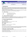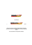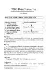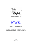
1
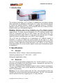
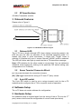
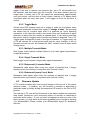
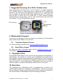
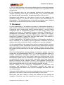
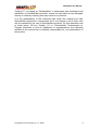
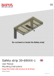
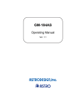
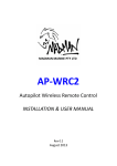
m-TX
User Manual
a
product
Note: This manual provides information on the AdaptAlert m-TX module
available for use with WirelessAlert products.
Please consult your WirelessAlert Agent or technician for assistance with the
more advanced m-TX applications.
Warning: Wiring of WirelessAlert products for control of ‘3 rd Party’, high
power, 230 V mains power and or three phase devices, must be performed by
a qualified electrician. Suitably rated external relays and contactors must be
used to prevent damage to products.
Pay close attention to the guarantee conditions.
AdaptAlert User Manual
Table of Contents
1Introduction.............................................................................................................................3
2Specifications..........................................................................................................................3
2.1General............................................................................................................................3
2.2Electrical..........................................................................................................................3
2.3RF Specifications.............................................................................................................4
3Onboard Features ..................................................................................................................4
3.1Onboard LED ..................................................................................................................4
3.2Screw Terminal Connector Block.....................................................................................4
3.38 pin DIP switch...............................................................................................................4
4Software Setup.......................................................................................................................4
5Hardware Setup......................................................................................................................4
6Configuration...........................................................................................................................5
6.1Setting the Dip Switch Code ...........................................................................................5
6.2Mode Selection................................................................................................................5
6.2.1Normal Mode............................................................................................................5
6.2.2Toggle Mode............................................................................................................6
6.2.3Multiple Transmit Mode............................................................................................6
6.2.4Single Transmit Mode...............................................................................................6
6.2.5Retransmit (1 minute) Mode ....................................................................................6
6.2.6Retransmit (every 5 sec) Mode.................................................................................6
6.3Firmware Update.............................................................................................................6
7Suggested Housing of m-TX for Outdoor Use.........................................................................7
8WirelessAlert Support.............................................................................................................7
8.1 Technical Support Contact..............................................................................................7
8.2Head Office Contact........................................................................................................7
9 Copyright notice.....................................................................................................................7
10 Guarantee............................................................................................................................7
11 Disclaimer............................................................................................................................8
Table of Figures
Figure 1: Miniature Transmitter (m-TX) module........................................................................3
Figure 2: m-TX Module Onboard Layout ..................................................................................4
Figure 3: m-TX module inside PVC housing.............................................................................7
Glossary of Terms
AC
DB
Dbi
DBm
DC
DIP
GSM
LED
mA
MA
MHz
m-TX
PIR
TA II
uA
Copyright InFocus Trading 111 cc, 2009
Alternating Current
Decibels
Decibel isotropic (For Antenna gain)
Decibel milliwatt (For Radio signal)
Direct Current
Dual inline package
Global System for Mobile Communications
Light Emitting Diode
Milli Amps
MaxAlert
Megahertz
433 MHz Mini transmitter
Passive Infra-Red
TextAlert II
Micro Amps
2
AdaptAlert User Manual
1 Introduction
Figure 1: Miniature Transmitter (m-TX) module
The miniature transmitter (m-TX) (Figure 1) operates as a miniature wireless
radio transmitter for adapting a wide range of ‘3 rd party’ wired sensor devices
to function as wireless devices, capable of triggering zones on VoiceAlert,
MaxAlert, and or TextAlert II (If you are not familiar with any of these products,
please contact your WirelessAlert Agent).
Warning: Operation and correct installation of m-TX modules requires
knowledge of how particular ‘3rd party’ sensor devices receive and respond to
trigger events. To ensure correct installation of m-TX modules, please make
sure you understand how the ‘3rd party’ sensor has been wired onto your
existing wired alarm panel ‘INPUT’ (if you have one) and the type of trigger
signal the sensor sends through to the ‘INPUT’ when triggered.
The m-TX can be configured for a combination of 6 different modes of
operation. It is vital you select the correct mode/s for the type of ‘3 rd party’
sensor used, otherwise you may interfere with the operation of the sensor and
prevent a trigger signal from being delivered to the ‘INPUT’ on your existing
wired alarm panel. If you are unsure, please contact your WirelessAlert Agent
for assistance.
2 Specifications
2.1
General
Dimensions: 45mm x 23mm x 15mm (excluding antenna)
Operating temperature: 0°C -50°C (32 F – 122 F)
Waterproof specification: None
2.2
Electrical
The m-TX can accept power voltages from 5 to 12v DC across its (+) and (-)
terminals. A 9v battery is an ideal power source. Alternatively, wire the m-TX
onto the 3rd party device’s power source.
The m-TX is designed to be extremely frugal in terms of power consumption.
It draws about 10uA under normal conditions (all modes), and about 35mA
while it is transmitting.
Warning: Do not connect power onto the (IN) / (IN) terminals as this may
damage the circuitry associated with these terminals. The (IN) / (IN) terminals
require ‘potential free only’ triggering from ‘3rd party’ devices.
Copyright InFocus Trading 111 cc, 2009
3
AdaptAlert User Manual
2.3
RF Specifications
433 MHz Transmitter module.
3 Onboard Features
Please refer to Figure 2
1
2
3
4
5
6
7
8
Figure 2: m-TX Module Onboard Layout
3.1
Onboard LED
The m-TX has a single onboard LED. Upon startup (connecting power), the
LED will give the user an indication of the selected operating mode. If it
flashes four times in quick succession, it means that “Toggle” mode is
selected. If it flashes only once, it means “Normal” (NO/NC) mode is selected.
The LED will further also light up each time the m-TX transmits a message.
Note: LED indication for the other modes is not provided. You can determine
additional mode settings by looking at the particular DIP switch setting (see
configuration of m-TX below).
3.2
Screw Terminal Connector Block
(+) / (-) power terminals for connection of power
(IN) / (IN) trigger terminals for wiring m-TX onto ‘3rd party’ sensor.
3.3
8 pin DIP switch
The 8 pin DIP switch is used to set a unique transmit code for the m-TX
modules and to configure the m-TX for a specific mode of operation.
4 Software Setup
The m-TX does not require software for configuration.
5 Hardware Setup
No hardware setup is required apart from the wiring of the m-TX onto the ‘3 rd
party’ sensor device and the configuration of correct mode (see below).
Copyright InFocus Trading 111 cc, 2009
4
AdaptAlert User Manual
6 Configuration
6.1
Setting the Dip Switch Code
The m-TX DIP switch code must be set to match a specific zone code present
on VoiceAlert, MaxAlert or TextAlert II in order to trigger zone when the 3rd
party sensor detects an intruder. Please refer to respective product User
Manuals for zone programming instructions. There are eight DIP switches
(pins) that can be set to either the ON (up) position or the OFF (down)
position. Set switches 1 to 5 to create a unique code for each m-TX (switches
1 to 5 are for code selection only and do not influence mode m-TX operation).
Set switches 6,7 and 8 depending on the mode of operation you require as
described in Mode Selection list below.
Note: Please make a record of all the DIP switch codes you have set on all
your m-TX modules for future reference if you wish to adjust zones and or for
adding additional m-TX modules to a specific zone.
6.2
Mode Selection
The most current firmware has six different modes of operation.
The m-TX can be configured for one or a combination of modes by the
adjusting DIP Switches 6, 7 and 8 on the DIP switch as follows:
•
If DIP8 is OFF, “Normal” mode is activated.
•
If DIP8 is ON, “Toggle” mode is activated.
•
If DIP7 is OFF, “Multiple Transmit” mode is activated.
•
If DIP7 is ON, “Single Transmit” mode is activated.
•
If DIP6 is OFF, “Retransmit every 1 min” mode is activated (does not
function in conjunction with “Toggle” mode).
•
If DIP6 is ON, “Retransmit every 5 sec” mode is activated (does not
function in conjunction with “Toggle” mode).
6.2.1 Normal Mode
In this mode, the m-TX will respond to a set of contacts closing or opening on
the IN terminals. When power is applied to the m-TX, it will sense the current
status of the input. If it senses that the input contact is currently closed (such
as when it is connected to a Normally Closed contact), then it will henceforth
wait for the contacts to open before transmitting. Conversely, if it senses that
the inputs are open during startup, it will henceforth sit around and wait for the
contacts to close before transmitting. If the activating condition persists, the
m-TX will transmit once every minute or once every 5 seconds (depending on
selected mode).
Example: The m-TX is connected to a door contact that is normally closed.
When the door is opened, the door’s magnetic contact switch opens. This
contact is wired into the input of the m-TX, and the m-TX battery is connected
while the door is closed. Thereafter, each time the door opens, the m-TX will
Copyright InFocus Trading 111 cc, 2009
5
AdaptAlert User Manual
trigger. If the door is opened, and remains ajar, the m-TX will transmit for a
few seconds, and then keep quiet for a minute. If the door remains open for
longer than 1 minute, the m-TX will repeat the transmission approximately
once per minute, until the door is finally closed. Had the m-TX battery been
connected while the door was open, it will trigger as soon as the door is
closed.
6.2.2 Toggle Mode
Certain wired PIR sensors tend not to supply a pulse on its contacts when
movement is detected. Instead they supply a “change of state”. So assuming
the sensor has its contacts open after it is powered up. Upon detecting
movement, it will close the contact, and remain close until movement is again
detected, at which time the contact is opened again. It can thus be said that
the sensor output is toggled each time that movement is detected. The m-TX
Toggle mode is designed to work in this type of scenario. In Toggle mode, the
m-TX will transmit for a short period each time the input changes. It will not
transmit once per minute, but instead will ONLY transmit once at each status
change event.
6.2.3 Multiple Transmit Mode
Each trigger event induces multiple (three to four) radio signal transmissions
in rapid succession.
6.2.4 Single Transmit Mode
Each trigger event induces a single radio signal transmission.
6.2.5 Retransmit (1 minute) Mode
Retransmits radio signal, after every one minute of elapsed time, if trigger
remains active (only works in conjunction with “Normal” mode).
6.2.6 Retransmit (every 5 sec) Mode
Retransmit radio signal, after every five seconds of elapsed time, if trigger
remains active (only works in conjunction with “Normal” mode).
6.3
Firmware Update
m-TX modules loaded with most current firmware will have all of the above
optional modes . In addition, you will be able to activate or deactivate a
particular mode by simply sliding the respective DIP switch to the ON or OFF
position.
The earliest m-TX units did not feature all of the above modes and required a
hard restart (disconnect, then reconnect power) to activate or deactivate a
particular mode setting. If your unit does not appear to enter any one of the
above modes, you may have its firmware upgraded free of charge by sending
it to WirelessAlert. Please contact your WirelessAlert Agent for assistance
with this.
Copyright InFocus Trading 111 cc, 2009
6
AdaptAlert User Manual
7 Suggested Housing of m-TX for Outdoor Use
Some applications will require use of m-TX outdoors. A suitable waterproof
PVC housing (Figure 3) should be used to protect the m-TX module and
batteries if you are using 9 Volt batteries to power the m-TX. Metal housings
are not suitable, as they will block the radio signal from the m-TX. Ideally, you
may be able to house the m-TX inside the ‘3rd party’ sensor’s housing
provided there is enough space to do so. This should be the case with some
of the larger ‘3rd party’ PIR and Beam sensors.
m-TX
PVC Housing
Rechargeable
Battery
Figure 3: m-TX module inside PVC housing.
8 WirelessAlert Support
If you have not managed to solve an issue by consulting your WirelessAlert
agent, please email details of your issue to:
8.1
Technical Support Contact
For Technical Support please email: [email protected]
8.2
Head Office Contact
For Sales and Agent Information please Email: [email protected] or
visit Website: www.wirelessalert.co.za
9 Copyright notice
All Information and images in this manual are copyrighted and proprietary to
WirelessAlert. The manual as a whole may be distributed and copied freely,
but no partial content may be used/copied or distributed in any way. No part of
WirelessAlert products (including any Hardware, Firmware and or Software)
may be copied or reverse-engineered. WirelessAlert reserves the right to
make changes to contents of this manual, without notice, at any time.
10 Guarantee
The AdaptAlert mini Transmitter (m-TX) is guaranteed for a period of 12
months against defects in materials or workmanship. Should your product
become defective during the guarantee period it will be repaired or replaced at
the sole discretion of WirelessAlert under the following conditions:
Copyright InFocus Trading 111 cc, 2009
7
AdaptAlert User Manual
A: The unit and enclosure must not have been opened or otherwise tampered
with. If the enclosure of any unit has been opened at all, the guarantee will be
null and void.
B: The guarantee does not cover damage resulting from excessive input
voltages, lightning, power surges or water damage. If any of these conditions
are detected during assessment, the guarantee will be null and void.
Assessment and opinion as to the status of each unit with regards to the
conditions named in “A” and “B”, above, will be at the sole discretion of
WirelessAlert. This guarantee does not provide for shipping costs. Shipping
costs will be for the account of the user under all circumstances.
11 Disclaimer
It is the responsibility of all installers and users of WirelessAlert products to
read and fully understand manuals supplied with the products, to comply with
all warnings and to communicate these to relevant parties. It must be clearly
understood that no WirelessAlert product is a ‘life saving’ device, and
installers and users of WirelessAlert systems indemnify WirelessAlert; its
management, shareholders, staff and suppliers, of all claims in this regard.
No claim may be brought in respect of WirelessAlert component or product
usage that is greater in total value than the retail value of the product or
component itself at the installation in question.
It is the responsibility of all installers and users of WirelessAlert products to
test all elements of the product, and all associated component parts and
settings upon setup, at any time that it is modified or in any way managed.
It is the responsibility of the owner of the system to ensure that the functions
and functionality of their WirelessAlert product and all associated component
parts and settings be tested at least once a week. Failure to test any aspect
will further void any claim that an end user might bring against developers and
suppliers.
Given that WirelessAlert products operate as wireless systems and must
comply with the limitations that ICASA, FCC, and other authorities impose on
wireless transmission strengths; and given that atmospheric and other
conditions might from time to time create or alter non-functional state for the
WirelessAlert system and its components, the Suppliers expressly state that
no guarantee of function can be given even when tests have previously
proven successful for one or another function. These vagaries of function are
therefore considered Acts of God - and provide the Suppliers with insulation
from prosecution that such Act of God conditions generally provide.
InFocus Trading 111 cc trading as “WirelessAlert” in association with
developers and distributors of WirelessAlert products will under no
circumstances be held liable for any injuries or damages that result from the
use of this product.
If any part of this disclaimer is found by a competent court to be invalid or non
applicable, it will have no effect on the enforceability of other terms.
Much effort has been made to ensure the contents of this manual are
complete, informative, easy and interesting to read, and accurate. InFocus
Copyright InFocus Trading 111 cc, 2009
8
AdaptAlert User Manual
Trading 111 cc trading as “WirelessAlert” in association with developers and
distributors of WirelessAlert products, cannot be held liable for any damages
directly or indirectly resulting from any errors in any manual.
It is the responsibility of the individual who reads this manual and uses
WirelessAlert products to communicate all of its contents to all of those who
will be impacted by the use of WirelessAlert products. By this disclaimer and
to these terms, InFocus Trading 111 cc, WirelessAlert Technologies cc,
Polygon Industries cc and all employees or representatives are expressly
relieved of all common law or statutory responsibility for non performance of
this product.
Copyright InFocus Trading 111 cc, 2009
9