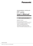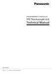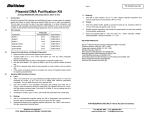
1
Safety Precautions Observe the following notices to ensure personal safety or to prevent accidents. To ensure that you use this product correctly, read this User’s Manual thoroughly before use. Make sure that you fully understand the product and information on safety. This manual uses two safety flags to indicate different levels of danger. WARNING If critical situations that could lead to user’s death or serious injury is assumed by mishandling of the product. -Always take precautions to ensure the overall safety of your system, so that the whole system remains safe in the event of failure of this product or other external factor. -Do not use this product in areas with inflammable gas. It could lead to an explosion. -Exposing this product to excessive heat or open flames could cause damage to the lithium battery or other electronic parts. CAUTION If critical situations that could lead to user’s injury or only property damage is assumed by mishandling of the product. -To prevent excessive exothermic heat or smoke generation, use this product at the values less than the maximum of the characteristics and performance that are assured in these specifications. -Do not dismantle or remodel the product. It could cause excessive exothermic heat or smoke generation. -Do not touch the terminal while turning on electricity. It could lead to an electric shock. -Use the external devices to function the emergency stop and interlock circuit. -Connect the wires or connectors securely. The loose connection could cause excessive exothermic heat or smoke generation. -Do not allow foreign matters such as liquid, flammable materials, metals to go into the inside of the product. It could cause excessive exothermic heat or smoke generation. -Do not undertake construction (such as connection and disconnection) while the power supply is on. It could lead to an electric shock. Copyright / Trademarks -This manual and its contents are copyrighted. -You may not copy this manual, in whole or part, without written consent of Panasonic Industrial Devices SUNX Co., Ltd. -Windows is a registered trademark of Microsoft Corporation in the United States and other countries. -All other company names and product names are trademarks or registered trademarks of their respective owners. PLC_ORG Introduction Thank you for buying a Panasonic product. Before you use the product, please carefully read the installation instructions and the users manual, and understand their contents in detail to use the product properly. Types of Manual • There are different types of users manual for the FP7 series, as listed below. Please refer to a relevant manual for the unit and purpose of your use. • The manuals can be downloaded on our website: http://industrial.panasonic.com/ac/e/dl_center/manual/ . Unit name or purpose of use FP7 Power Supply Unit FP7 CPU Unit Manual name Manual code FP7 CPU Unit Users Manual (Hardware) WUME-FP7CPUH FP7 CPU Unit Command Reference Manual WUME-FP7CPUPGR FP7 CPU Unit Users Manual (Logging Trace Function) WUME-FP7CPULOG FP7 CPU Unit Users Manual (Security Function) WUME-FP7CPUSEC FP7 CPU Unit Users Manual (LAN Port Communication) WUME-FP7LAN FP7 series Users Manual (SCU communication) WUME-FP7COM FP7 Extension Cassette (Communication) (Ethernet type) FP7 series Users Manual (Communication cassette Ethernet type) WUME-FP7CCET FP7 Extension (Function) Cassette Analog Cassette FP7 Analog Cassette Users Manual WUME-FP7FCA Instructions for Built-in LAN Port Instructions for Built-in COM Port FP7 Extension Cassette (Communication) (RS-232C/RS485 type) FP7 Digital Input/Output Unit FP7 Digital Input/Output Unit Users Manual WUME-FP7DIO FP7 Analog Input Unit FP7 Analog Input Unit Users Manual WUME-FP7AIH FP7 Analog Output Unit FP7 Analog Output Unit Users Manual WUME-FP7AOH FP7 High-speed counter Unit FP7 High-speed counter Unit Users Manual WUME-FP7HSC FP7 Pulse Output Unit FP7 Pulse Output Unit Users Manual WUME-FP7PG FP7 Positioning Unit FP7 Positioning Unit Users Manual WUME-FP7POSP FP7 Serial Communication Unit FP7 series Users Manual (SCU communication) WUME-FP7COM PHLS System PHLS System Users Manual WUME-PHLS Programming Software FPWIN GR7 FPWIN GR7 Introduction Guidance WUME-FPWINGR7 Table of Contents Table of Contents 1. Unit Functions and Restrictions ....................................... 1-1 1.1 1.2 Unit Functions and How They Work ......................................................1-2 1.1.1 Functions of Cassettes ............................................................................ 1-2 1.1.2 Types and Model Numbers of Cassettes ................................................ 1-2 Restrictions on Combinations of Units ...................................................1-3 1.2.1 Restrictions on Power Consumption ....................................................... 1-3 1.2.2 Applicable Versions of Unit and Software ............................................... 1-3 1.2.3 Restrictions on the Combination of Extension Cassettes ....................... 1-3 2. Specifications .................................................................... 2-1 2.1 2.2 Analog I/O Cassette and Analog Input Cassette .................................... 2-2 2.1.1 Input Specifications (AFP7FCA21 / AFP7FCAD2) ................................ 2-2 2.1.2 Output Specifications (AFP7FCA21) ..................................................... 2-3 2.1.3 Switch Settings ........................................................................................ 2-4 2.1.4 Wiring ...................................................................................................... 2-5 2.1.5 Input Conversion Characteristics (AFP7FCA21 / AFP7FCAD2)............. 2-7 2.1.6 Output Conversion Characteristics (AFP7FCA21) .................................. 2-8 Thermocouple Input Cassette .............................................................. 2-10 2.2.1 Input Specifications ............................................................................... 2-10 2.2.2 Switch Settings ...................................................................................... 2-10 2.2.3 Wiring .................................................................................................... 2-11 2.2.4 Input Conversion Characteristics .......................................................... 2-11 3. I/O Allocation and Programs ............................................. 3-1 3.1 I/O Allocation .........................................................................................3-2 3.1.1 3.2 Sample Programs ..................................................................................3-3 3.2.1 ii I/O Allocation ........................................................................................... 3-2 Example of Analog Input/Output ............................................................. 3-3 Table of Contents 3.2.2 Example of Thermocouple Input ............................................................. 3-3 iii Table of Contents iv 1 Unit Functions and Restrictions Unit Functions and Restrictions 1.1 Unit Functions and How They Work 1.1.1 Functions of Cassettes Using these cassettes attached to the CPU unit enables analog I/O control. • An analog input and analog output can be controlled by attaching these extension cassettes to the CPU unit. • It is selectable from three types of cassettes in accordance with the intended use. Input and output with simple programs • For input data, a digital conversion value (0 to 4000) is read as an input device (WX). • For output data, a digital value (0 to 4000) is converted to analog output data by being written into an output device (WY). The input and output range is switchable. • The range can be switched with the switches on each cassette. The current input is switched according to wirings. Equipped with the thermocouple disconnection alarm function (Thermocouple input cassette) • When a thermocouple is disconnected, the value is digitally converted to the fixed value (K8000) so that you can determine the situation is not normal. 1.1.2 Types and Model Numbers of Cassettes Name FP7 Extension Cassette (Function Cassette) 1-2 Model No. Analog I/O cassette 2-ch Input, 1-ch output AFP7FCA21 Analog input cassette 2-ch input AFP7FCAD2 Thermocouple input cassette 2-ch input AFP7FCTC2 1.2 Restrictions on Combinations of Units 1.2 Restrictions on Combinations of Units 1.2.1 Restrictions on Power Consumption The internal current consumption of the unit is as follows. Make sure that the total current consumption is within the capacity of the power supply with consideration of all other units used in combination with this unit. Name Specifications FP7 Extension Cassette (Function Cassette) Analog I/O cassette 2-ch Input, 1-ch output Model No. Current consumption AFP7FCA21 75 mA or less Analog input cassette 2-ch input AFP7FCAD2 40 mA or less Thermocouple input cassette 2-ch input AFP7FCTC2 45 mA or less 1.2.2 Applicable Versions of Unit and Software For using the above function cassettes, the following versions of unit and software are required. Item Applicable version FP7 CPU unit Ver.2.0 or later Programmingn tool software FPWIN GR7 Ver.1.4 or later 1.2.3 Restrictions on the Combination of Extension Cassettes There are following restrictions depending on units and cassettes to be used. Attachable extension cassettes Unit type Number of attachable cassettes Communication cassette AFP7CCS* AFP7CCM* Communication cassette AFP7CCET Function cassette AFP7FC* CPU Unit Max. 1 unit ● ● ● Serial Communication Unit Max. 2 units per unit ● Not attachable Not attachable 1-3 Unit Functions and Restrictions 1-4 2 Specifications Specifications 2.1 Analog I/O Cassette and Analog Input Cassette 2.1.1 Input Specifications (AFP7FCA21 / AFP7FCAD2) Input specifications Items Description No. of input points 2 channels (non-insulated between channels) Input range Voltage 0-10 V, 0-5 V (Can be set individually. Switchable) Current 0 -20 mA Digital conversion value K0 - K4000 (Note 1) Resolution 1/4000 (12-bit) Conversion speed 1 ms/channel Total accuracy ±1% F.S. or less (0 - 55 °C) Input impedance Absolute max. input Insulation method Voltage 1 MΩ Current 250 Ω Voltage -0.5 V, +15 V (Voltage input) Current +30 mA (Current input) Between analog input terminal and internal digital circuit part: Transformer insulation, isolation IC insulation Between analog input terminal and analog output terminal: Transformer insulation, isolation IC insulation Note1) When the analog input values exceed the upper and lower limits of the input range, the digital values maintain the upper and lower limit values. (Note 2) Because of 12-bit resolution, the higher 4 bits of digital conversion value are always zero. (Note 3) The time shown in the figure below is required to reflect analog input values in the input device area (WX) read by the CPU unit. (Note 4) Averaging is not processed within the cassettes. Perform averaging with programs as necessary. 2-2 2.1 Analog I/O Cassette and Analog Input Cassette 2.1.2 Output Specifications (AFP7FCA21) Output specifications Items Description No. of output points Output range 1 channel/cassette Voltage 0 – 10 V, 0 – 5 V (Switchable) Current 0 – 20 mA Digital value K0 - K4000 Resolution 1 / 4000 (12-bit) Conversion speed 1 ms/channel Total accuracy ±1% F.S. or less (0 - 55 °C) Output impedance 0.5 Ω (Voltage output) Output max. current 10 mA (Voltage output) Output allowable load resistance 600 Ω or less (Current output) Insulation method Between analog output terminal and internal digital circuit part: Transformer insulation, isolation IC insulation Between analog output terminal and analog input terminal: Transformer insulation, isolation IC insulation Precautions on the characteristics of analog I/O cassette When the power to the CPU unit turns on or off, voltage (equivalent to 2 V) may be output for approx. 2 ms from the analog I/O cassette. If it will be a problem on your system, take necessary measures externally to avoid the transitional condition, e.g. turning on PLC before external devices or turning off external devices before PLC. 2-3 Specifications 2.1.3 Switch Settings • Set the range selection switches on the cassette before wiring. Range selection switches (AFP7FCA21) SW No. 1 2 3 Name Output range selection switch (Note) CH0 input range selection switch CH1 input range selection switch Voltage / Current I/O 10 V 0 to +10 V 5V 0 to +5 V 10 V 0 to +10 V 5 V/I 0 to +5 V / 0 to +20 mA 10 V 0 to +10 V 5 V/I 0 to +5 V / 0 to +20 mA When using it as analog current output, it works in either case, regardless of the setting of the switches. Range selection switches (AFP7FCAD2) SW No. Name 1 CH0 input range selection switch 2 CH1 input range selection switch Voltage / Current input 10 V 0 to +10 V 5 V/I 0 to +5 V / 0 to +20 mA 10 V 0 to +10 V 5 V/I 0 to +5 V / 0 to +20 mA Switch on the back of the cassette • Always turn OFF the switch mounted on the printed wiring board on the back of the cassette. 2-4 2.1 Analog I/O Cassette and Analog Input Cassette 2.1.4 Wiring Wiring Diagram Voltage input Current input Analog device Analog device *1 V V I I COM COM *1: For the current input, short-circuit the V and I terminals. Voltage output Current output V V I Analog device I Analog device COM COM Precautions on wiring • Use double-core twisted-pair shielded wires. It is recommended to ground them. However, depending on the conditions of the external noise, it may be better not to ground the shielding. • Do not have the analog input wiring close to AC wires, power wires, or load. Also, do not bundle it with them. • Do not have the analog output wiring close to AC wires, power wires, or load. Also, do not bundle it with them. Terminal block • On the output circuit, a voltage amplifier and a current amplifier is connected in parallel to one D/A converter IC. Do not connect an analog device to the voltage output terminal and current output terminal of the same channel simultaneously. Voltage amplifier DA converter micro-com puter Current amplifier 2-5 Specifications Terminal layout (AFP7FCA21) Voltage input V COM V COM V COM Output device OUT CH0 IN CH1 IN Current input I COM V ※1 I COM V ※1 I COM Output device OUT CH0 IN CH1 IN *1: Connect the V and I terminals for using it as current input. Terminal layout (AFP7FCAD2) Voltage input V COM V COM CH0 CH1 Current input V *1 I COM V *1 I COM *1: Connect the V and I terminals for using it as current input. 2-6 CH0 CH1 2.1 Analog I/O Cassette and Analog Input Cassette 2.1.5 Input Conversion Characteristics (AFP7FCA21 / AFP7FCAD2) 0V to 10V DC input Conversion characteristics graph Table of A/D converted values Input voltage (V) 0.0 2.0 4.0 6.0 8.0 10.0 Digital value 0 800 1600 2400 3200 4000 When exceeding the rated range Input voltage (V) A/D converted value 0 V or less (Negative value) 0 10 V or more 4000 0V to 5V DC input Conversion characteristics graph Table of A/D converted values Input voltage (V) 0.0 1.0 2.0 3.0 4.0 5.0 Digital value 0 800 1600 2400 3200 4000 When exceeding the rated range Input voltage (V) A/D converted value 0V or less (Negative value) 0 5 V or more 4000 0mA to 20mA DC input Conversion characteristics graph Table of A/D converted values Input current (mA) 0.0 5.0 10.0 15.0 20.0 Digital value 0 1000 2000 3000 4000 When exceeding the rated range Input current (mA) Digital value 0 mA or less (Negative value) 0 20 mA or more 4000 2-7 Specifications 2.1.6 Output Conversion Characteristics (AFP7FCA21) 0V to 10V DC output Conversion characteristics graph Table of D/A converted values Digital value 0 800 1600 2400 3200 4000 Output voltage (V) 0.0 2.0 4.0 6.0 8.0 10.0 When exceeding the rated range Digital input value Output voltage (V) Negative value (Note) 4001 or more 10.0 (Note) Digital input values are processed as unsigned 16-bit data (US). 0V to 5V DC output Conversion characteristics graph Table of D/A converted values Digital value 0 800 1600 2400 3200 4000 Output voltage (V) 0.0 1.0 2.0 3.0 4.0 5.0 When exceeding the rated range Digital input value Negative value (Note) 4001 or more (Note) Digital input values are processed as unsigned 16-bit data (US). 2-8 Output voltage (V) 5.0 2.1 Analog I/O Cassette and Analog Input Cassette 0mA to 20mA output Conversion characteristics graph Table of D/A converted values Digital value Output current (mA) 0 1000 2000 3000 4000 0.0 5.0 10.0 15.0 20.0 When exceeding the rated range Digital value Output current (mA) Negative value (Note) 4001 or more 20.0 (Note) Digital input values are processed as unsigned 16-bit data (US). 2-9 Specifications 2.2 Thermocouple Input Cassette 2.2.1 Input Specifications Input specifications Items Description No. of input points 2 channels (insulated between channels) Input range Thermocouple type K (-50.0 to 500.0 °C), Thermocouple type J (-50.0 to 500.0 °C) Digital value In normal condition K – 500 to K5000 When exceeding rated range K – 501, K5001 or K8000 When wire is broken K8000 (Note 1) When getting data ready K8001 (Note 2) Resolution 0.2 °C (The indication is 0.1 °C by the software averaging procedure.) (Note 3) Conversion speed 100 ms / 2 channels Total accuracy 0.5% F.S. + Cold junction error 1.5 °C Input impedance 344 kΩ Insulation method Transformer insulation, isolation IC insulation (Note 1) When the wire of thermocouple is broken or disconnected, the digital value will change to K8000 within 70 seconds. For replacing the thermocouple, program a process for avoiding a risk that would be resulted from the disconnecting. (Note 2) From the Power-on to the converted data Ready, the digital conversion value will be K8001. Make a program not to use the data in the meantime as conversion values. (Note 3) Although the resolution of the hardware is 0.2 °C, it will be a conversion value by 0.1 °C by the internal averaging procedure. 2.2.2 Switch Settings • Set the range selection switches on the cassette before wiring. Thermocouple selection switches(AFP7FCTC2) SW No. Name Thermocouple 1 CH0 thermocouple selection switch (Note) J Type J K Type K 2 CH1 thermocouple selection switch (Note) J Type J K Type K (Note) For the thermocouple selection switch, the setting at the time of power-on is effective for the operaiton. Note the setting will not be updated even if the switch is changed during the operation. Switch on the back of the cassette • Always turn OFF the switch mounted on the printed wiring board on the back of the cassette. 2-10 2.2 Thermocouple Input Cassette 2.2.3 Wiring Precautions on wiring • Keep the space more than 100 mm between the input line and the power line/high-voltage line. • It is recommended to ground the unit using the shielded compensating lead wire. Terminal layout(AFP7FCTC2) N.C. N.C. + - CH0 N.C. + - CH1 N.C. N.C. (Note) The N.C. terminals are used by the system. Do not connect anything. 2.2.4 Input Conversion Characteristics Range of Thermocouples type K and J Conversion characteristics graph Table of A/D converted values Temperature Digital value -50.1 -50 0 50 500 500.1 -501 -500 0 500 5000 5001 When exceeding the rated range -50.1 °C or less Temperature Digital value K -501 500.1 °C or more K 5001 or K 8000 When wire is broken K 8000 2-11 Specifications 2-12 3 I/O Allocation and Programs I/O Allocation and Programs 3.1 I/O Allocation 3.1.1 I/O Allocation • The I/O areas of the CPU unit are allocated to each cassette. • An area of one word (16 points) is allocated to a channel. Specifications Input Output CH0 CH1 CH0 Analog I/O cassette 2-ch Input, 1-ch output WX2 WX3 WY2 Analog input cassette 2-ch input WX2 WX3 - Thermocouple input cassette 2-ch input WX2 WX3 - (Note) The starting numbers of I/O contacts of each unit including the CPU unit can be changed by the setting of tool software. 3-2 3.2 Sample Programs 3.2 Sample Programs 3.2.1 Example of Analog Input/Output • For analog input, digital conversion values are read from the device area (WX) of the input relay. • For analog output, digital conversion values are written into the device area (WY) of the output relay. SR13 R100 MV.UL U0 DT100 MV.US U0 DT200 MV.US WX2 DT100 MV.US WX3 DT101 DT200 WY2 Data save area is initialized. Analog input Digital conversion value is read. R200 MV.US Analog output Digital conversion value is written. 3.2.2 Example of Thermocouple Input • For thermocouple input, digital conversion values are read from the device area (WX) of the input relay. • Make a program not to use the values as normal converted data until the completion of data preparation at the time of power-on, or when disconnecting is detected. SR13 R0 DT100 =. SS K8001 DT101 =. SS K8001 DT100 =. SS K8000 DT101 =. SS K8000 R0 R100 R990 R0 R101 R991 MV.SL K0 DT100 MV.SL K0 DT200 MV.SS WX2 DT100 MV.SS WX3 DT101 Data save area is initialized. Thermocouple input Digital conversion value is read. R100 R101 The completion of preparation is confirmed. R990 R991 MV.SS DT100 DT200 MV.SS DT101 DT201 Disconnecting is detected. When data is normally converted, Digital conversion value is transferred. 3-3 I/O Allocation and Programs 3-4 Record of changes Manual No. Date Record of Changes WUME-FP7FCA-01 MAR.2014 First Edition