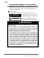
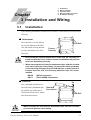
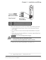
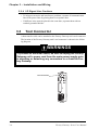
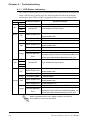
1
Factory Gateway User Manual (Pro-Designer Compatible) Preface Thank you for purchasing the Pro-face Graphic Logic Controller Factory Gateway Series (hereby referred to as “Factory Gateway” or “Factory Gateway unit”). This unit is designed to be connected to an External Device (PLC, etc.) that does not have its own Ethernet interface, via the Pro-Designer system’s Ethernet connection. Pro-Designer also allows the Factory Gateway unit to communicate with a host-level PC without specialized programming. This allows data collection and sharing of data with other PLC units. Also, Pro-Designer’s packaged software, Pro-eView, allows you to display and to operate a maintenance screen from a host-level or a remote PC. In this manual’s examples, the Mitsubishi MELSEC-AnA Series PLC is used whenever possible, connected in a one-to-one relationship with a Factory Gateway unit. < Note > 1. It is forbidden to copy the contents of this manual, in whole or in part, except for the user’s personal use, without the express permission of Digital Electronics Corporation of Japan. 2. The information provided in this manual is subject to change without notice. 3. This manual has been written with care and attention to detail; however, should you find any errors or omissions, contact Digital Electronics Corporation and inform them of your findings. 4. Please be aware that Digital Electronics Corporation shall not be held liable by the user for any damages, losses, or third party claims arising from any uses of this product. All Company/Manufacturer names used in this manual are the registered trademarks of those companies. © Copyright 2002 Digital Electronics Corporation Factory Gateway Series User Manual 1 Preface Table of Contents Preface ........................................................................................................................ 1 Essential Safety Precautions ................................................................................... 4 General Safety Precautions .................................................................................... 7 Factory Gateway Models......................................................................................... 8 Package Contents ..................................................................................................... 8 UL/c-UL (CSA) Application Notes ........................................................................ 9 CE Marking Notes ................................................................................................. 9 Documentation Conventions................................................................................. 10 CHAPTER 1 INTRODUCTION 1.1 System Design ............................................................................................... 1-1 1.2 Accessories .................................................................................................... 1-3 CHAPTER 2 SPECIFICATIONS 2.1 General Specifications................................................................................. 2-1 2.1.1 Electrical ............................................................................................ 2-1 2.1.2 Environmental.................................................................................... 2-2 2.1.3 Structural ............................................................................................ 2-3 2.2 Functional Specifications ............................................................................ 2-3 2.2.1 Memory .............................................................................................. 2-3 2.2.2 Clock .................................................................................................. 2-3 2.2.3 Interfaces ............................................................................................ 2-3 2.3 Interface Specifications............................................................................... 2-4 2.3.1 Serial Interface (COM) ..................................................................... 2-4 2.4 Part Names and Functions ......................................................................... 2-6 2.5 Dimensions .................................................................................................... 2-8 CHAPTER 3 INSTALLATION AND WIRING 3.1 Installation .................................................................................................... 3-1 3.2 Wiring Cautions ........................................................................................... 3-2 3.2.1 Connecting the Power Cord .............................................................. 3-2 3.2.2 Connecting the Power Supply .......................................................... 3-4 3.2.3 Grounding .......................................................................................... 3-5 3.2.4 I/O Signal Line Cautions .................................................................. 3-6 2 3.3 Tool Connector ............................................................................................. 3-6 3.4 Ethernet Cable Connector .......................................................................... 3-7 Factory Gateway Series User Manual Preface 3.5 IP Address Settings ...................................................................................... 3-8 CHAPTER 4 TROUBLESHOOTING 4.1 Troubleshooting............................................................................................ 4-1 4.1.1 LED Status Indicators ....................................................................... 4-2 4.1.2 Diagnosing Problems ........................................................................ 4-3 4.2 Periodic Check Points ................................................................................. 4-4 Factory Gateway Series User Manual 3 Preface Essential Safety Precautions This manual includes procedures that must be followed to operate the FACTORY GATEWAY correctly and safely. Be sure to read this manual and any related materials thoroughly to understand the correct operation and functions of the FACTORY GATEWAY unit. Safety Symbols Please pay attention to the following safety symbols and their meanings: WARNING Indicates situations that may result in major machine damage, severe bodily injury, or death if the instructions are not followed. CAUTION Indicates situations that may result in damage to the machinery, or minor bodily injury if the instructions are not followed. WARNINGS System Design • Please design your system so that equipment will not malfunction due to a communication fault between the Factory Gateway and its host controller This is to prevent any possibility of bodily injury or material damage. • Do not use the Factory Gateway unit as a warning device for critical alarms that can cause serious operator injury, machine damage or production stoppage. Critical alarm indicators and their control/activator units must be designed using stand-alone hardware and/or mechanical interlocks. • The Factory Gateway is not appropriate for use with aircraft control devices, aerospace equipment, central trunk data transmission (communication) devices, nuclear power control devices, or medical life support equipment, due to these devices’ inherent requirements of extremely high levels of safety and reliability. 4 Factory Gateway Series User Manual Preface WARNINGS • When using the Factory Gateway with transportation vehicles (trains, cars and ships), disaster and crime prevention devices, various types of safety equipment, non lifesupport related medical devices, etc. redundant and/or failsafe system designs should be used to ensure the proper degree of reliability and safety. Installation • High voltage runs through the Factory Gateway. Never disassemble the Factory Gateway, otherwise an electric shock can occur. • Do not modify the Factory Gateway unit. Doing so may cause a fire or an electric shock. • Do not use the Factory Gateway in an environment where flammable gasses are present, since operating the Factory Gateway may cause an explosion. Wiring • To prevent an electric shock, be sure to confirm that the Factory Gateway’s power cord is not connected to the main power when connecting any cords, cables or lines to the Factory Gateway. • Be sure to replace the Factory Gateway’s plastic terminal block cover after wiring is completed, since operating the Factory Gateway without the cover may lead to an electric shock. • Do not use power beyond the Factory Gateway’s specified voltage range. Doing so may cause a fire or an electric shock. Maintenance • The Factory Gateway uses a lithium battery for backing up its internal clock data. If the battery is incorrectly replaced, the battery may explode. To prevent this, please do not replace the battery yourself. When the battery needs to be replaced, please contact your local Factory Gateway distributor. Factory Gateway Series User Manual 5 Preface CAUTIONS Installation • Be sure to securely connect all cable connectors to the Factory Gateway. A loose connection may cause incorrect input or output. Wiring • Ground the Factory Gateway’s FG line separately from other units’ FG lines. Putting these FG lines too close may cause an electric shock or unit malfunction. Be sure to use a Ω or less and a 2mm2 or thicker grounding resistance of 100Ω wire, or your country’s applicable standard. • When wiring the Factory Gateway, be sure that the rated voltage and terminal layout are within the designated range. If the voltage supplied differs from the rated voltage, or incorrect wiring or grounding is performed, it may cause a fire or unit malfunction. • Use only the designated torque to tighten the Factory Gateway’s terminal block screws. If these screws are not tightened firmly, it may cause a short-circuit, fire, or Factory Gateway malfunction. • Be careful that metal filings and wiring debris do not fall inside the Factory Gateway, since they can cause a fire, Factory Gateway malfunction, or incorrect operation. Unit Disposal • When this unit is disposed of, it should be done so according to your country’s regulations for similar types of industrial waste. 6 Factory Gateway Series User Manual Preface General Safety Precautions • Do not install the Factory Gateway where the ambient temperature can exceed the allowed range. Doing so may cause the Factory Gateway to malfunction or shorten its operation life. • Do not restrict or limit the Factory Gateway’s naturally occurring rear-face ventilation, or store or use the Factory Gateway in an environment that is too hot. • Do not use this unit in areas where large, sudden temperature changes can occur. These changes can cause condensation to form inside the unit, possibly causing the unit to malfunction. • Do not allow water, liquids, metal or charged particles to enter inside the Factory Gateway’s case, since they can cause either a Factory Gateway malfunction or an electrical shock. • Do not use or store the Factory Gateway in direct sunlight, or in excessively dusty or dirty environments. • Do not store or use the unit where strong jolting or excessive vibration can occur. • Do not store or use the Factory Gateway where chemicals (such as organic solvents, etc.) and acids can evaporate, or where chemicals and acids are present in the air. Corrosive chemicals: Acids, alkalies, liquids containing salt Flammable chemicals: Organic Solvents • Do not use paint thinner or organic solvents to clean the Factory Gateway. • Do not connect or disconnect the communication cable to the host machine while the power is ON. Factory Gateway Series User Manual 7 Preface Factory Gateway Models The Factory Gateway Series in this manual refers to the following Factory Gateway model number: Series Name Model Number Comments Factory Gateway FGW-SE41-24V UL/c-UL (CSA) Approved CE Marked Package Contents The following items are included in the Factory Gateway’s package. Before using the Factory Gateway, please confirm that all items listed here are present. Factory Gateway Unit (1) (FGW-SE41-24V) Installation Guide (1) Installation Guide This unit has been carefully packed, with special attention to quality. However, should you find anything damaged or missing, please contact your local Factory Gateway distributor immediately. 8 Factory Gateway Series User Manual Preface UL/c-UL (CSA) Application Notes The FGW-SE41-24V is a UL/c-UL (CSA) recognized unit. (UL File No. E220851) The FGW-SE41-24V unit conforms to the following standards. UL508 Electrical Control System for Industry CAN/CSA-C22.2 No.1010-1 (Safety requirements for electrical equipment for measurement and laboratory use) FGW-SE41-24V (UL Registration Model: 3080034-01) <Notes> The Factory Gateway must be installed in other equipment. If the unit is installed in an area with no air conditioning system, be sure to attach the DIN rail to the rear of the unit. Also, be sure the unit is installed so it is at least 100 mm away from all of the unit’s directions except the rear side. If these requirements are not met, the heat generated by the unit’s internal components may cause the unit to fail to meet UL standards requirements. The power supply unit connected to the I/O unit must be a UL/cUL (CSA) approved Class 2 power supply unit or Class 2 transformer*1. When the Factory Gateway or multiple I/O units under load are operated with a single power supply, the amount of current consumption and full-load current of the I/O units must be within the rated load of the Class 2 power supply unit or Class 2 power supply transformer. Be aware that the number of points which can be turned ON simultaneously may be limited, depending on the amount of load and load current value. *1.A Class 2 power supply unit or Class 2 power supply transformer is 30V and, at 8A or less output, less than 100VA. (Prescribed by National Electrical Code.) CE Marking Notes The FGW-SE41-24V is a CE Marked unit that conforms to EMC directives EN55011 Class A and EN61000-6-2. <Caution> While this unit is officially marked as conforming to the relevant EMC directives, it is the user’s final application of this unit in a larger system (i.e. the machinery, wiring, control panel, installation method, etc.) that will determine if this unit maintains or loses this conformance marking. Therefore, it is strongly advised that the user investigate and confirm whether their overall system (i.e. all related machinery and equipment) also conforms with these EMC directives. Factory Gateway Series User Manual 9 Preface Documentation Conventions The list below describes the documentation conventions used in this manual. Symbol Meaning Indicates important information or procedures that must be followed for correct and risk-free software/device operation. Screen Creation Software Pro-eView PLC * Indicates the Pro-Designer (Ver. 4.0 or later) Indicates the software that displays screens created by the Screen Creation Software using Internet Explorer. Abbreviation for Programmable Logic Controller. Indicates additional important information. Indicates an important hint or explanation. 10 Factory Gateway Series User Manual 1. System Design 2. Accessories Chapter 1 Introduction 1.1 System Design The following diagram represents the main selection of devices connectable to the Factory Gateway unit. Factory Gateway RUN Mode Peripherals RUN Mode Edit Mode Pro-eView Client Pro-eView Client Internet Ethernet Factory Gateway Unit (1) (3) (4) RS-232C Cable GP410-IS00-O* 1 RS-422 Cable GP230-IS11-O*1 GP230-IS12-O*1 (for Multi-link cable) (5) RS-422 Connector Terminal Adapter GP070-CN10-O*1 2-Port Adapter II Cable GP070-MDCB11 Mitsubishi PLC A, Q, C, FX Series (6) 2-Port Adapter II Host Controller (PLCs, etc.) GP070-MD11 Mitsubishi PLC A-Series Program Port I/F Cable (6) GP430-IP10-O Mitsubishi PLC FX-Series Program Port I/F Cable (6) GP430-IP11-O *1.Certain PLC types and models cannot be connected. Pro-Designer On-line Help Factory Gateway Series User Manual 1–1 Chapter 1 – Introduction Factory Gateway Edit Mode Peripherals Pro-Designer Ethernet Factory Gateway Unit *3 (2) (1) Ethernet Data Transfer Cable GPW-CB02 Pro-Designer Personal Computer *2 Factory Gateway Interfaces PLC Interfaces (1) Ethernet (4) RS-232C Port (2) Tool Connector (5) RS-422 Port (3) Serial Interface (6) Programming Console Port *2.For the full range of compatible PCs, refer to the following manual. Pro-Designer On-line Help *3.Normally, maintenance (data transfer) is possible using an Ethernet network. However, depending on the data transfer cable used, a Factory Gateway System Error may occur, preventing communication. 1–2 Factory Gateway Series User Manual Chapter 1 – Introduction 1.2 Accessories All optional equipment listed here is produced by Digital Electronics Corporation. Available Software Product Name Model No. Pro-Designer Ver. 4.0 or later (including Pro-eView) PS-DWE01-V40 Pro-eView License PS-EPR01 Description Software used to create screen data and to set protocol to use the remote monitoring feature (Pro-eView) or the data sharing feature of Internet Explorer on Factory Gateway. Software license to use Pro-eView on Factory Gateway. Tool Connector Product Name *1 Model No. GPW-CB02 Data Transfer Cable Description Cable to connect Factory Gateway with a PC and to transfer screen data from Pro-Designer. *1.Normally, maintenance (data transfer) is possible using an Ethernet network. However, depending on the data transfer cable used, a Factory Gateway System Error may occur, preventing communication. Serial Interfaces Model No. Product Name *1 RS-232C Cable *1 RS-422 Cable RS-422 Terminal Block Adapter *1 Description GP410-IS00-O GP230-IS11-O Interface cables between the host (PLC) and the Factory Gateway. GP070-CN10-O Conversion adapter to convert serial data to RS-422 format. 2 Port Adapter II GP070-M D11 2 Port Adapter II Cable GP070-M DCB11 M itsubishi A Series GP430-IP10-O Programming Port I/F Cable M itsubishi FX Series GP430-IP11-O Programming Port I/F Cable Interface unit that allows use of both Factory gateway and M itsubishi A, Q, C and FX series equipment in the same location. Connects the Factory Gateway to the 2-Port Adapter II. Connects directly to M itsubishi's PLC I/F Programming Console. Simultaneous use of program console, however, is not possible. *1.For details about the range of connectable PLCs: Pro-Designer On-line Help Maintenance Items Product Name Connector Cover Factory Gateway Series User Manual Model No. PS-BH00 Description Side face connector cover. 1–3 Memo 1–4 Factory Gateway Series User Manual Chapter 2 Specifications 2.1 1. 2. 3. 4. 5. General Specifications Functional Specifications Interface Specifications Part Names and Functions Dimensions General Specifications 2.1.1 Electrical Rated Voltage Rated Voltage Range Allowable Voltage Drop Power Consumption In-Rush Current Voltage Endurance Insulation Resistance Factory Gateway Series User Manual DC 24V DC 19.2V to DC 28.8V 10ms max. 10W max. 30A max. AC 500V 20mA for 1 minute (between charging and FG terminals) 10M Ω or more at DC 500V (between charging and FG terminals) 2–1 Chapter 2 – Specifications 2.1.2 Environmental Ambient Operating Temperature Storage Temperature Ambient Humidity Storage Humidity Air Purity (Dust) Atmosphere Atmosheric Endurance (Factory Gateway Operation Altitude) Shock Resistance Vibration Resistance Noise Immunity (via noise simulator) Electrostatic Discharge Immunity o o 0 C to +55 C o o -20 C to +60 C 10%RH to 90%RH o (non-condensing, wet bulb temperature: 39 C max.) 10%RH to 90%RH o (non-condensing, wet bulb temperature: 39 C max.) 3 0.1mg/m max. (non-conductive levels) Free of corrosive gasses 800hPa to 1,114hPa (2000 meters max.) IEC61131-2 (JIS B 3501) compliant 2, (147m/s three times for each [X, Y, Z] direction) IEC61131-2 (JIS B 3501) compliant When Vibration is NOT Continuous 2 10Hz to 57Hz 0.075mm, 57Hz to 150Hz 9.8m/s When Vibration is Continuous 2 10Hz to 57Hz 0.035mm, 57Hz to 150Hz 4.9m/s (10 times [80 min.] for each [X, Y, Z] direction) Noise Voltage: 1200Vp-p, Pulse Duration: 1µs Rise Time: 1ns Contact Discharge M ethod 6kV (complies with IEC 61000-4-2 Level 3) 2.1.3 Structural Grounding External Dimensions Weight Cooling Method 2–2 100Ω max., or your country’s applicable standard W37mm x H131mm x D105mm [1.46 in.x 5.16 in. x 4.13 in.] Approx. 0.6 kg [1.32 lb] Natural air circulation Factory Gateway Series User Manual Chapter 2 – Specifications 2.2 Functional Specifications 2.2.1 Memory 4MB FLASH EPROM Application 2.2.2 Clock ±65 seconds/month (at room temperature) Clock Accuracy The FACTORY GATEWAY unit’s internal clock has a slight error. At normal operating temperatures and conditions, with the FACTORY GATEWAY operating from its lithium battery, the degree of error is 65 seconds per month. Variations in operating conditions and battery life can cause this error to vary from -380 to +90 seconds per month. For systems where this degree of error will be a problem, the user should be sure to monitor this error and make adjustments when required. Pro-Designer On-line Help 2.2.3 Interfaces Serial Interface (COM) Ethernet Interface Tool Connector Asynchronous Transmission: RS232C/RS422 Data Length: 7 or 8 bits Stop Bit: 1 or 2 bits Parity: None, Odd or Even Data Transmission Speed: 2,400 to 115,200bps IEEE802.3, 10BASE-T Asynchronous TTL level nonprocedural command I/F Used for transferring data between the Pro-Designer and the Factory Gateway. Factory Gateway Series User Manual 2–3 Chapter 2 – Specifications 2.3 Interface Specifications 2.3.1 Serial Interface (COM) This interface can be either RS-232C or RS-422. It connects the FACTORY GATEWAY to the Host (PLC). This interface uses a socket-type connector. Pin Assignments SIO 1 14 25 13 Pin # Signal Name Condition 1 2 3 4 5 6 7 8 9 10 11 12 13 14 15 16 17 18 19 20 21 22 23 24 25 FG SD RD RS CS DR SG CD TRMX RDA SDA NC NC VCC SDB RDB RI CSB ERB ER CSA ERA NC NC NC Frame ground Send data (RS-232C) Receive data (RS-232C) Request send (RS-232C) Clear send (RS-232C) Data Set Ready (RS-232C) Signal ground Carrier detect (RS-232C) Termination (RS-422) Receive data A (RS-422) Send data A (RS-422) No connection (Reserved) No connection (Reserved) 5V±5% output 0.25A Send data B (RS-422) Receive data B (RS-422) Ring Indicate (RS-232C) Clear send B (RS-422) Enable receive B (RS-422) Enable receive (RS-232C) Clear send A (RS-422) Enable receive A (RS-422) No connection (Reserved) No connection (Reserved) No connection (Reserved) Recommended Parts Connector Dsub25pin plug XM2A-2501 (OMRON) Cover Dsub25pin cover XM2S-2511 (OMRON) Dsub25pin cover XM2S-2521 (OMRON) Jack Screws (OMRON) Cable XM2Z-0071 CO-MA-VV-SB5P x 28AWG (Hitachi Cable Ltd.) Use rough metric type M2.6x0.45 p threads used to secure the cable’s set screws. Pro-Designer On-line Help 2–4 Factory Gateway Series User Manual Chapter 2 – Specifications Use the following instructions to create your own cable: With an RS-422 cable: • The following pins must be shorted as follows: #18 (CSB) and #19 (ERB) #21 (CSA) and #22 (ERA) • Connecting the RS-422 cable’s #9 (TRMX) and #10 (RDA) pins inserts a termination resistance of 100Ω between #10 (RDA) and #16 (RDB). • When making a cable for a Memory Link system, use a 4-wire type cable. With an RS-232C cable: • Do NOT use the following pins: #9 (TRMX), #10 (RDA), #11 (SDA), #15 (SDB), #16 (RDB), #18 (CSB), #19 (ERB), #21 (CSA), #22 (ERA) • Connect the #1 (FG) terminal only if it is required by a connected device. • This FACTORY GATEWAY unit’s serial port is not isolated. When the host (PLC) unit is also not isolated, and to reduce the risk of damaging the RS-422 circuit, be sure to connect the #7 SG (Signal Ground) terminal. • Pin #14 (VCC) DC 5V Output is not protected. To prevent damage or unit malfunction, use only the designated level of current. Factory Gateway Series User Manual 2–5 Chapter 2 – Specifications 2.4 Part Names and Functions A : Tool Connector Connects the data transfer cable when transferring data for maintenance. B : Ethernet I/F (10BASE-T) Provides a 10BASE-T interface. C : Network Status LED These LEDs are positioned vertically and indicate the Ethernet data transfer status. Location Color Indicates Not Lit Indicates Upper Green Ready to transfer data Not connected to network / Network trouble Lower Yellow Transferring data Not transferring data F G A B H C D I J E K Front D : Serial I/F(Dsub 25pin) Used for the Dsub25 pin’s RS-232C and RS422 cables. Is connected to the Host (PLC.) 2.3 Interface Specifications E : Power Input Terminal Block Connects the power cord. F : Power LED (PWR) This LED indicates the Factory Gateway’s status. LED Green Orange Red Not Lit Factory Gateway Status Normal operation Transferring data Unit malfunction No power is available G : Error Status LED (STA) LED Green Orange Red Not Lit Factory Gateway Status Normal operation System program error/Data error Run-time Application program error including a PLC communication error Unit malfunction For details, see 4.1.1 LED Status Indicators 2–6 Factory Gateway Series User Manual Chapter 2 – Specifications H : Serial I/F (TxD) When this indicator blinks, data is being sent. I : Serial I/F (RxD) When this indicator blinks, data is being received. J : Reset Switch (RST) Resets the Factory Gateway unit. K : DIP Switches When Pro-Designer Runtime is installed using an Ethernet network in either a new (factory settings) Factory Gateway unit, or a Factory Gateway unit that has already been set up using GP-PRO/PBIII system data, be sure to turn Factory Gateway unit dip switches 5 and 6 “ON” (System Overwrite Enabled). If Pro-Designer runtime has been previously installed, the Factory Gateway unit's dip switches do not need to be changed. The Factory Gateway unit's factory-shipped dip switch settings are “OFF”. This setting is recommended for protecting the Factory Gateway unit's data. F G A B H C I J D E K Front L L : DIN Rail Attachment Holder M *1 M: Rotary Switches These switches are used to set the unit’s IP Address. The factory settings are “0”. For details, see 3.5 Setting IP Addresses Right Side *1. This section is used only for maintenance by Pro-face. Do not open this cover. Factory Gateway Series User Manual 2–7 Chapter 2 – Specifications 2.5 Dimensions Unit:mm [in.] (9[0.35]) 105[4.13] (8[0.31]) 131[5.16] (4.5 [0.18]) 37[1.46] Front 2–8 Right Side Factory Gateway Series User Manual 1. 2. 3. 4. 5. Installation Wiring Cautions Tool Connector Ethernet Cable Connector IP Address Settings Chapter 3 Installation and Wiring 3.1 Installation The following information explains how to attach a 35mm DIN rail to the Factory Gateway. Attachment Place the unit’s curved, bottom DIN Rail lip over the bottom of the DIN rail, and tilt the unit up until the top face attachment clip clicks Factory Gateway into place. • Be sure that the top and bottom faces of the unit are correctly oriented and that the unit is vertical. Incorrect installation may prevent heat from dissipating correctly. • When removing the unit from the attachment clips, hold the unit with your hand to prevent it from falling. To prevent the Factory Gateway unit from being dislodged from the DIN Rail due to being struck or bumped from the side, the following Stabilizer Clips are recommended. BNL5P (IDEC Corporation) HDV-1 (TOYO GIKEN Corporation) Removal Up Use a standard screwdriver to force the unit’s attachment clip up until the top of the unit is freed from the rail. Next, tilt the Standard Screwdriver DIN Rail unit down and remove. When removing the unit from the attachment clips, hold the unit with your hand to prevent it from falling. Factory Gateway Series User Manual 3–1 Chapter 3 – Installation and Wiring 3.2 Wiring Cautions 3.2.1 Connecting the Power Cord WARNINGS • To avoid an electric shock, prior to connecting the Factory Gateway’s power cord terminals to the power terminal block, confirm that the Factory Gateway's power supply is completely turned OFF, via a breaker, or similar unit. • The Factory Gateway FGW-SE41-24V unit is designed to use only DC24V input. Any other power level can damage both the Factory Gateway and the power supply. • Since there is no power switch on the Factory Gateway unit, be sure to attach a breaker type switch to its power cord. • When the FG terminal is connected, be sure the wire is grounded. Otherwise, an electric shock can occur when the unit is broken. • To avoid a short caused by loose ring terminals, be sure to use ring terminals with an insulating sleeve. • When the FG terminal is connected, be sure the wire is grounded. Not grounding the Factory Gateway unit will result in excess noise and vibration. • The SG and FG terminals are connected internally in the Factory Gateway unit. • When connecting the SG line to another device, be sure that the design of the system does not produce a shorting loop. • Wherever possible, use thick wires (max. 2 mm2) for power terminals, and twist the wire ends before attaching the ring terminals. • Be sure to use the following size ring terminals.*1 Ring Terminal *1 3–2 Suggested Ring Terminal : V2-MS3 (made by JST) Factory Gateway Series User Manual Chapter 3 – Installation and Wiring Ring Terminals*1 Power Input Terminal Block Front Positive Electrode Negative Electrode Frame ground (connected to FGW chassis) + FG When connecting the power cord, be sure to follow the procedures given below. 1. Confirm that the Factory Gateway’s Power Cord is disconnected from the power supply. 2. Use a screwdriver to remove the Power Input Terminal Block’s clear plastic cover. 3. Remove the screws from the middle three (3) terminals, align the Ring Terminals and reattach the screws. See 3.2.2 Connecting the Power Supply • Confirm that the wires are connected correctly. • The torque required to tighten these screws is 0.5 N•m. 4. Replace the Power Input Terminal Block’s clear plastic cover. *1 Suggested Ring Terminal : V2-MS3 (made by JST) Factory Gateway Series User Manual 3–3 Chapter 3 – Installation and Wiring 3.2.2 Connecting the Power Supply • When supplying power to the Factory Gateway unit, separate the input/output and operation unit lines (see Diagram 1). • To increase the noise resistance quality of the power cord, twist each power wire before attaching the Ring Terminal. Dia. 1 Main power source FGW Power I/O power source Dia. 2 Main power source FGW Unit I/O device FGW Power FGW • The power supply cord must not be bundled or positioned close to main circuit lines (high voltage, high current), or input/ output signal lines (see Diagram 2). • Connect a lightning surge absorber (see Diagram 3) to deal with power surges. I/O power source I/O device I/O power I/O device Main circuit power Dia. 3 • To avoid excess noise, make the power cord as short as possible. • Ground the surge absorber (E1) separately from the Factory Gateway unit (E2). Operation Unit FGW FG E1 E2 Lightning surge absorber • Select a surge absorber with a maximum circuit voltage that is greater than that of the power supply’s peak voltage. 3–4 Factory Gateway Series User Manual Chapter 3 – Installation and Wiring 3.2.3 Grounding CAUTION Do NOT use common grounding, since it can lead to an accident or machine breakdown. Connect the FG terminal found on the back of the Factory Gateway unit to an exclusive ground (diagram A). (A) Exclusing Grounding (BEST) FGW Another device Ω. • Make sure that the grounding resistance is less than 100Ω • The FG and SG lines are connected internally in the Factory Gateway. • The grounding wire should have a cross-sectional area of at least 2 mm2. Create the grounding point as close to the Factory Gateway unit as possible, and keep the wire as short as possible. Replace thin wire with a thicker wire, and place it in a duct. • When connecting the SG line to another device, be sure that the design of the system does not produce a shorting loop. If exclusive grounding is not possible, use a common connection point (diagram B). (B) Common Grounding (OK) FGW Another device (C) Common Grounding (Not OK) FGW Another device If the equipment does not function properly when grounded, disconnect the ground wire from the FG terminal. Factory Gateway Series User Manual 3–5 Chapter 3 – Installation and Wiring 3.2.4 I/O Signal Line Cautions • To help prevent noise and interference problems, separate all communication lines from power lines by placing them in a separate duct. • If different wires must be placed in the same duct, separate them with an earthed/ grounded divider. 3.3 Tool Connector A data transfer cable can be attached to the Factory Gateway unit’s tool connector. The location of the Factory Gateway unit’s tool connector is shown in the following diagram. WARNINGS To prevent an electrical shock, be sure to unplug the Factory Gateway unit’s power cord from the main power supply prior to attaching or detaching any connectors to or from the Factory Gateway. Tool Connector Front 3–6 Factory Gateway Series User Manual Chapter 3 – Installation and Wiring 3.4 Ethernet Cable Connector The Factory Gateway Ethernet interface is IEEE802.3 compliant, and transmits data at 10 Mbps. The Ethernet connector’s location is shown below. Ethenet interface Front • Pro-face strongly recommends that a trained engineer install your Ethernet network. • You may not be able to use the 1:1 connection by a cross cable depending on PCs or network cards. Be sure to connect those with a hub. Factory Gateway Series User Manual 3–7 Chapter 3 – Installation and Wiring 3.5 IP Address Settings To set the Factory Gateway unit’s IP address, the 8 side face rotary switches are used. To set these switches, you must first remove the right face Rotary Switch Cover. The factory settings are all “0”. Also, the Factory Gateway unit’s IP address is set using HEX. The example below uses an IP address (DEC) of 192.168.0.1. Decimal Hexadecimal 192 C0 IP Address 168 0 A8 00 1 01 Rotary Switch Settings • Be sure to enter all IP address settings prior to connecting the Factory Gateway unit to the power supply. If power is connected to the Factory Gateway unit prior to setting these switches, a communication (illegal IP address) error will occur. In this case, please disconnect the Factory Gateway unit’s power supply, set these switches, and reconnect the power supply. • The “Subnet Mask” and “Default Gateway” settings are not set via these switches. They are set using the Pro-Designer software and then sent to the Factory Gateway unit. Pro-Designer On-line Help • The IP Addresses should be set as follows: 00.00.00.01 -> 7F.FF.FF.FE (0.0.0.1 to 127.255.255.254) 80.00.00.01 -> BF.FF.FF.FE (128.0.0.1 to 191.255.255.254) C0.00.00.01 -> DF.FF.FF.FE (192.0.0.1 to 223.255.255.254) • After setting the IP Addresses, be sure to reattach the cover. 3–8 Factory Gateway Series User Manual 1. Troubleshooting 2. Periodic Check Points Chapter 4 Troubleshooting 4.1 Troubleshooting The following information explains how to troubleshoot the Factory Gateway unit. The first steps should always be to check the following items. • Is the Factory Gateway receiving the correct level of power? • Is the Device/PLC receiving the correct level of power? • Is the Factory Gateway correctly connected tot he Device/PLC? • Is the Factory Gateway unit’s current protocol data correct for the type of Device/PLC that is connected? Factory Gateway Series User Manual 4–1 Chapter 4 – Troubleshooting 4.1.1 LED Status Indicators The Factory Gateway unit uses two LED indicators (PWR nad STA) to display the status of the Factory Gateway unit.The following table describes the problems indicated by these LEDs, and gives suggestions for how to solve each problem. Lamp Name PWR STA OFF OFF Green Red Orange Green OFF Green Red Orange Red OFF Green Red Orange OFF Green Orange Red Orange Problem/Condition No power Normally OFF Possible Solution(s) Power supply is not operating. If lit, a hardware error has occurred. Reinstall the run-time system using the run-time installer via the data transfer cable. Factory Gateway Error If lit, a hardware error has occurred. (Run-time system is operating Normally) No problem Reinstall the run-time system using the run-time installer via System Program Error the data transfer cable. Factory Gateway Error If lit, a hardware error has occurred. Incorrect IP Address Correct the unit’s current rotary switch IP Address settings. Confirm the contents of system variables for storing error Run-time Application messages using Pro-eView or the data-sharing feature, and Error perform appropriate treatment depending on each error. System Program Error Normally OFF If lit, a hardware error has occurred. Reinstall the run-time system using the run-time installer via the data transfer cable. Factory Gateway Error Possible hardware error. Transferring data (Transferring data) Reinstall the run-time system using the run-time installer via System Program Error the data transfer cable. Factory Gateway Error Possible hardware error. Incorrect IP Address Correct the unit's current rotary switch IP Address settings. Confirm the contents of system variables for storing error Run-time Application messages using Pro-eView or the data-sharing feature, and Error perform appropriate treatment depending on each error. System Program Error When a hardware error occurs, please contact your local Proface distributor for service and repair. 4–2 Factory Gateway Series User Manual Chapter 4 – Troubleshooting 4.1.2 Diagnosing Problems The following solutions may solve the problem. Unable to transfer data CAUSE1: The network settings are incorrect. SOLUTION: Enter them correctly in Pro-Designer, and transfer the project file again. CAUSE2: The protocol settings are incorrect. SOLUTION: Using Pro-Designer, confirm if the correct Device/PLC has been set. If an incorrect protocol has been set, correct the setting and transfer the project file again. CAUSE3: The protocol communication settings are incorrect. SOLUTION: Enter them correctly in Pro-Disigner, and transfer the project file again. Unable to Refer to Data or Perform Data-sharing with Pro-eView CAUSE1: Pro-Designer/Data-Sharing data settings are incorrect. SOLUTION: Enter them correctly in Pro-Designer, and transfer the project file again. CAUSE2: The network settings are incorrect. SOLUTION: Enter them correctly in Pro-Designer, and transfer the project file again. For troubleshooting details, refer to Pro-Designer On-line Help. Factory Gateway Series User Manual 4–3 Chapter 4 – Troubleshooting 4.2 Periodic Check Points To keep your Factory Gateway unit in good condition, be sure to inspect the following points periodically. Operation Environment • Is the operating temperature within the allowable range (0° C to 55° C)? • Is the operating humidity within the specified range (10%RH to 90%RH, wet bulb temperature of 39° C or less)? • Is the operating atmosphere free of corrosive gasses? Electrical Specifications • Is the input voltage (DC 19.2V to DC 28.8V) appropriate? Related Items • Are all power cords and cables connected properly? Have any become loose? • Is the DIN rail holding the unit securely? 4–4 Factory Gateway Series User Manual