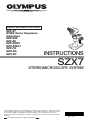
1
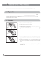
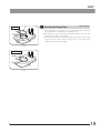
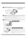
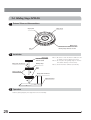
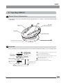
Modules described in this manual
SZ2-ST
WHSZ Series Eyepieces
Objectives
SZX-EPA
SZX-AS
SZX-STAD1
SZH-STAD1
SZ2-FO
SZH-SG
SZH-SC
INSTRUCTIONS
SZX7
STEREOMICROSCOPE SYSTEM
This instruction manual is for the Olympus stereomicroscope system. To ensure the safety,
obtain optimum performance and to familiarize yourself fully with the use of this microscope,
we recommend that you study this manual thoroughly before operating the microscope.
Retain this instruction manual in an easily accessible place near the work desk for future
reference.
This publication is printed on 100% recycled paper
AX6631
This device complies with the requirements of directive 98/79/EC concerning in vitro diagnostic medical
devices. CE marking means the conformity to the directive.
SZX7
CONTENTS
Correct assembly and adjustments are critical for the microscope to manifest its full performance. If you are going
to assemble the microscope by yourself, please read Chapter 8, “ASSEMBLY” (pages 16 to 18). For the assemblies of the modules for which instruction manuals are available, refer to their instruction manuals.
IMPORTANT
1-2
— Be sure to read this chapter for safe use of the equipment. —
1
NOMENCLATURE
3
2
CONTROLS
4
3
OBSERVATION PROCEDURE
5
4
OPERATION
6-12
4-1 Stand......................................................................................................................................................................................................................... 6
1 Using the Stage
2 Adjusting the Focus Adjustment Knob Tension
4-2 Observation Tube ............................................................................................................................................................................ 6-9
1 Adjusting the Interpupillary Distance
2 Adjusting the Diopter (Zoom Confocality Adjustment)
3 Using the Eye Shades
4 Using an Eyepiece Micrometer Disk
5 Selecting the Light Path (SZX-TR30)
6 Adjusting the Tilt (SZX-TBI)
4-3 Microscope Body ...................................................................................................................................................................... 10-11
1 Zoom Magnification Indication
2 Switching the Click Stop ON-OFF
3 Using Auxiliary Sleeve SZ2-ET
4-4 TV Observation and Photomicrography .............................................................................................................. 12
5
TROUBLESHOOTING GUIDE
13
6
SPECIFICATIONS
14
7
OPTICAL PERFORMANCE
15
8
ASSEMBLY
16-18
9
OPTIONAL MODULES
19-27
SZX-EPA, SZX-AS, SZX-STAD1, SZH-STAD1, SZ2-FO, SZH-SG, SZH-SC
IMPORTANT
The SZX7 stereomicroscope is provided with the ESD (Electro-Static Discharge) protection specifications. It is provided
with electroconductive coating in the external finish to reduce the surface resistance and grounding lead wires in their
standard stand or system to eliminate static electricity from them.
CAUTION
To maintain the ESD protection performance, always use the microscope in combination with the
modules described in this manual or options having the ESD protection specifications. Otherwise,
the grounding will not work properly.
SAFETY PRECAUTIONS
1. After the equipment has been used in an observation of a specimen that is accompanied with a potential of infection,
clean the parts coming in contact with the specimen to prevent infection.
· Moving this microscope is accompanied with the risk of
dropping the specimen. Be sure to remove the specimen
before moving this product.
· Hold the bottom of the stand with one hand while holding
base column with the other hand to avoid tilting the microscope.
· In case the specimen is damaged by erroneous operation,
promptly take the infection prevention measures.
2. The desktop should be a level surface with an inclination of less than 3°, and the load to the microscope should be less
than 7 kg (when the SZ2-ST standard stand is used).
The microscope may become unstable when certain intermediate attachment and/or photography unit are mounted on
it. Be careful so that the microscope does not topple down.
3. When the microscope is to be disposed of, follow your local industrial waste disposal regulations.
If you have any questions, please contact Olympus.
1
Getting Ready
1. A microscope is a precision instrument. Handle it with care and avoid subjecting it to sudden or severe impact.
2. Do not use the microscope where it is subjected to direct sunlight, high temperature and humidity, dust or vibrations. (For
the operating conditions, see Chapter 6, “SPECIFICATIONS” on page 14.)
3. Do not turn the zoom adjustment knobs beyond the stopper positions. Otherwise, the internal mechanism may be
damaged.
Do not turn the left and right zoom adjustment knobs in the opposite directions, as this will result in a failure.
4. Only one intermediate attachment having thickness up to 60 mm can be mounted on the microscope. If two intermediate attachments or an intermediate attachment thicker than 60 mm is mounted, the image may be cut a little.
However, the coaxial reflected light illuminator (SZX-ILLC) is not counted in the number of intermediate attachment.
}When using multiple modules, they should be stacked in order of the SZX-ILLC, SZX-AS, SZX-RFA (SZX-RFL), SZX-SDO,
SZX-APT, SZX-BS, SZX-DA, SZX-FAD and SZX-EPA from the bottom to the top.
1
SZX7
2
Maintenance and Storage
1. Clean all glass components by wiping gently with gauze. To remove fingerprints or oil smudges, wipe with gauze slightly
moistened with a mixture of ether (70%) and alcohol (30%).
Since solvents such as ether and alcohol are highly flammable, they must be handled carefully. Be sure to keep
these chemicals away from open flames or potential sources of electrical sparks –– for example, electrical
equipment that is being switched on or off. Also remember to always use these chemicals only in a well-ventilated room.
2. Do not attempt to use organic solvents to clean the microscope components other than the glass components because
they use plastic resin materials extensively. To clean them, use a lint-free, soft cloth slightly moistened with a diluted
neutral detergent.
3. Do not disassemble any part of the microscope as this could result in malfunction or reduced performance.
3
Caution
If the microscope is used in a manner not specified by this manual, the safety of the user may be imperiled. In addition,
the equipment may also be damaged. Always use the equipment as outlined in this instruction manual.
The following symbols are used to set off text in this instruction manual.
: Indicates that failure to follow the instructions in the warning could result in bodily harm to the
user and/or damage to equipment (including objects in the vicinity of the equipment).
# : Indicates that failure to follow the instructions could result in damage to equipment.
} : Indicates commentary (for ease of operation and maintenance).
2
NOMENCLATURE
* Modules marked * are given the ESD specifications.
(Note) The modules shown in the following diagram are merely the typical examples. For the modules that are not shown
below, please consult Olympus or the latest catalogues.
Observation Tube
Eyepiece
· Binocular Tube: SZX-BI45*
· Binocular Tube: SZX-BI30
· Trinocular Tube: SZX-TR30
· Tilting Tube: SZX-TBI
· WHSZ10X*
· WHSZ10X-H*
· WHSZ15X-H*
· WHSZ20X*
· WHSZ20X-H*
· WHSZ30X-H*
Intermediate Attachment
· AS Unit: SZX-AS
· Eye Point Adjuster: SZX-EPA
· Coaxial Reflected Light Illuminator: SZX-ILLC
Stand
Microscope Body
Note 1)
· Standard Stand: SZ2-ST*
· LED Illuminator Stand: SZ2-ILST
· 7X Zooming Microscope Body: SZX-ZB7*
Objective
· DFPL0.5X-4*
· DFPL0.75X-4*
· DFPLAPO1X-4*
· SZX-ACH1X*
· SZX-ACH1.25X*
· DFPL1.5X-4*
· DFPL2X-4*
Stage Plate
· Black/White: SZ2-SPBW*
(ESD protection on black surface)
· Transparent: SP-C
· Other stage adapter
Auxiliary Sleeve
· SZ2-ET*
Note 1) The microscope can also be mounted on the SZ2-STU1/STU2/STU3 large stand as well as on the SZX-ST SZX
standard stand by using the SZ2-STB1/SZ2-STS focusing arm.
3
SZX7
CONTROLS
Zoom magnification indication (Page 10)
Indicates 0.8, 1, 1.25, 1.6, 2, 2.5, 3.2, 4, 5 and 5.6
Eye shades (Page 8)
Click stop ON-OFF screw (Page 10)
Zoom adjustment knobs (Page 7)
0.8X to 5.6X
Eyepiece clamping knobs
Focus adjustment knob (Page 6)
Stroke: 120 mm
Body clamping knob
Threaded for accessory
mounting
Accessory mounting holes
Diameter 4 mm (x 2)
Accessory mounting screws
(x 5)
Stage plate
Allen screwdriver
Allen screwdriver holder (Page 16)
With double-side adhesive tape.
Stage adapter mounting screws
M4 screws (x 2)
For
Grounding holes (Page 16)
4 mm banana plugs (x 4)
4
OBSERVATION PROCEDURE
}If you have not assembled the microscope yet, please read Chapter 8, “ASSEMBLY” (pages 16 to 18).
3-1 Preparation
(Page)
...................................................................................................................
1. Confirm the mounting, particularly that of the observation tube.
(P. 16 - 18)
2. Adjust the rotation tension of the focus adjustment knob. ................................................................................................................................................... (P. 6)
3. Prepare the light source as required.
3-2 Procedure
1. Place the specimen on the stage. (Page 6)
2. Adjust the interpupillary distance. (Page 6)
3. Adjust the eyepiece diopter. (Page 7)
· The adjustment operation is variable whether the eyepieces use
an eyepiece micrometer disk or not.
4. Set the zoom adjustment knob @ for the lowest magnification and rotate
the focus adjustment knob ² to bring the specimen into approximate
focus.
1
²
5. Rotate the zoom adjustment knob @ to the target magnification and
rotate the focus adjustment knob ² to bring the specimen into accurate
focus.
}When the optional AS unit (SZX-AS) is used, the contrast of image and
the focal depth of specimen can be adjusted with the aperture iris
diaphragm lever.
5
SZX7
OPERATION
4-1 Stand
1
Using the Stage
1. When reflected light illumination is used, the stage plate can be placed
either the white or black surface facing up depending on the specimen.
However, when the ESD performance is required, always use the black
surface of the stage plate.
2. When transmitted light illumination is used, use the transparent glass
stage plate (SP-C).
2
To decrease
Adjusting the Focus Adjustment Knob Tension
(Fig. 1)
}This operation is intended to facilitate the rotation of the knobs while
preventing spontaneous drop of the microscope body. It is recommended
to set the knob tension to a slightly higher level than the point where
spontaneous drop occurs.
1. Hold the left and right focus adjustment knobs @ with both hands, fix the
left knob and rotate the right knob. The rotation tension of the knobs
increases or decreases according to the direction in which the right knob
is rotated.
2. If the rotation tension is increased too much, accurate focusing is not
possible and the mechanism may be damaged.
Clamp.
To increase
1
Fig. 1
4-2 Observation Tube
1
1
Adjusting the Interpupillary Distance
(Fig. 2)
# Always hold the eyepiece sleeves @ with both hands when adjusting the interpupillary distance.
While holding the left and right eyepiece sleeves @ with both hands,
look through the eyepieces and adjust for binocular vision until the left
and right fields of view coincide completely.
Fig. 2
6
2
Adjusting the Diopter (Zoom Confocality Adjustment)
(Fig. 3)
# Confirm that the eyepiece clamping knobs @ are tightened firmly
before proceeding to the adjustment.
³
²
|
1
Eyepieces without eyepiece micrometer disk
1. Turn the diopter adjustment rings ² of the left and right eyepieces to
positions “0”. (This adjustment is not possible with eyepieces without
helicoids.)
2. Place an easy-to-observe specimen on the stage plate.
3. Set the zoom adjustment knob ³ for the lowest magnification and rotate
the focus adjustment knob | to bring the specimen into focus.
4. Set the zoom adjustment knob ³ for the highest magnification and
rotate the focus adjustment knob | to bring the specimen into focus.
5. Set the zoom adjustment knob ³ for the lowest magnification and rotate
the diopter adjustment rings ² of the left and right eyepieces, instead of
the focus adjustment knob, to bring the specimen into focus.
}Set the zoom adjustment knob ³ for the highest magnification again
and check the image focusing. The diopter adjustment is complete if the
image in accurate focus. If not, repeat steps 3 to 5 above.
Fig. 3
Eyepieces with eyepiece micrometer disk
1. Look through the eyepiece with eyepiece micrometer disk and rotate its
diopter adjustment ring ² to bring the micrometer scale into focus.
2. Place an easy-to-observe specimen on the stage plate.
3. Set the zoom adjustment knob ³ for low magnification, look through the
eyepiece with eyepiece micrometer disk and rotate the focus adjustment
knob | to bring the specimen into focus.
4. Set the zoom adjustment knob ³ for the highest magnification, look
through the eyepiece with micrometer disk and rotate the focus adjustment knob | to bring the specimen into focus.
5. Set the zoom adjustment knob ³ for the lowest magnification and rotate
the diopter adjustment ring of the eyepiece without eyepiece micrometer
disk, instead of the focus adjustment knob, to bring the specimen into
focus.
}Set the zoom adjustment knob ³ for the highest magnification again
and check the image focusing. The diopter adjustment is complete if the
image in accurate focus. If not, repeat steps 3 to 5 above.
}Note the left and right diopter scale values so that it can be quickly
duplicated in future observations.
Diopter scale of the 10X eyepieces
}The valid range of the diopter scale is between -8 and +5 but a slight
margin is added to it. Therefore, the diopter value may exceed +5 or -8
when it is adjusted to the maximum. In this case, whether the diopter
value is over +8 or under -5 can be identified by the length of the
eyepiece.
-8
7
+5
SZX7
3
Using the Eye Shades
(Fig. 4)
# The eye shades are not provided with ESD protection performance.
When ESD protection is required, do not use the eye shades.
When Wearing Eyeglasses
Use with the eye shades in the normal, folded-down position. This will
prevent the eyeglasses from being scratched.
When Not Wearing Eyeglasses
Extend the folded eye shades in the direction of the arrow to prevent
extraneous light from entering between the eyepieces and eyes.
Fig. 4
²
Indication engraved
surface
4
Using an Eyepiece Micrometer Disk
(Fig. 5)
WHSZ10X-H/15X-H/20X-H (Fig. 5)
@
Fig. 5
1. Rotate the disk-mounting ring @ of the eyepiece counterclockwise to
remove.
2. Prepare an eyepiece micrometer disk ² (24 mm dia. x 1.5 mm thick),
remove dust and dirt from its surface, and fit it into the disk-mounting ring
@ so that the engraving on the micrometer disk faces downward.
3. Gently screw in the disk-mounting ring @ incorporating the eyepiece
micrometer disk into the eyepiece. Turn the ring clockwise to attach it
firmly.
WHSZ30X-H (Fig. 6)
Indication engraved
surface
1. Rotate the disk-mounting ring ³ of the eyepiece counterclockwise to
remove.
2. Rotate the push ring | of the eyepiece micrometer disk counterclockwise to remove.
3. Prepare an eyepiece micrometer disk ƒ (24 mm dia. x 1.5 mm thick),
remove dust and dirt from its surface, place it on the disk-mounting ring
³ with the engraving facing downward, and fix it with the push ring |.
4. Gently screw in the disk-mounting ring ³ incorporating the eyepiece
micrometer disk into the eyepiece. Turn the ring clockwise to attach it
firmly.
# Due to their structures the WHSZ20X-H/30X-H eyepieces apply a
magnification on the focused plane of the eyepiece micrometer disk.
These magnifications are 1.3X with the WHSZ20X-H and 2X with the
WHSZ30X-H. Be sure to compensate for these magnifications when
using the eyepiece micrometer disk in measurements.
Also, insertion of the eyepiece micrometer disk extends the light
path length and deviates the position of the diopter scale. Correct
this deviation by turning the diopter adjustment ring of the eyepiece
toward “+”.
}When the eyepiece micrometer disk is not used, store it by wrapping in a
clean, soft cloth.
8
5
Selecting the Light Path (SZX-TR30)
(Fig. 7)
Slide the light path selector knob @ to select the desired light path.
1
Light Path Selector Knob
Indication
Pushed-in position
Pulled-out position
Light Path Ratio
Binocular 100%
Binocular
20%
TV & Photo 80%
Fig. 7
6
Adjusting the Tilt (SZX-TBI)
(Fig. 8)
5 to 45°
}Adjust the height and tilt of the observation tube to obtain the most comfortable viewing position.
Holding the binocular section with both hands, raise or lower it to the
desired position.
# Never attempt to force the binocular section past the upper or lower
stop position. Applying excessive force could destroy the limiting
mechanism.
Fig. 8
9
SZX7
4-3 Microscope Body
1
1
Zoom Magnification Indication
(Figs. 9 & 10)
|
The body zoom magnification is indicated on zoom adjustment knob
(right) @.
The total magnification can be calculated with the following formula.
Total
Objective
Body zoom
Eyepiece
=
X
X
magnification magnification magnification magnification
Fig. 9
Total magnification indication ring (Fig. 10)
}An objective other than the 1X model is provided with two total magnification indication rings*. Use the ring having indication “SZX7” with the
SZX7 microscope.
* : The indicated figures are the total magnification when the 10X eyepiece is used.
1. Widen the magnification indication ring ² and fit into the deep part of
the left zoom adjustment knob ³ so that the indicated figures can be
read from the front of the microscope.
2. Gently turn the magnification indication until it clicks into the predetermined position.
# The magnification indication ring can also be attached on the right
zoom adjustment knob, but the microscope zoom magnification
indication is hidden in this case.
³
²
Fig. 10
2
Switching the Click Stop ON-OFF
(Fig. 9)
}The click stop function provides a click stop for each zoom magnification
value indicated on the zoom adjustment knob. When the click stop
function is switched OFF, the zoom magnification can be adjusted finely
around each zoom magnification value.
1. To switch the click stop function ON, turn the click stop screw | clockwise (in the direction of the arrow) all the way until it is stopped using the
Allen screwdriver.
A click stop is provided for each zoom magnification value indicated on
the zoom magnification indication @.
2. To switch the click stop function OFF, turn the click stop screw | counterclockwise (in the opposite direction to the arrow) by about 2 turns using
the Allen screwdriver.
# To prevent damaging the microscope cover and internal mechanism, do not turn the screw excessively.
10
3
Microscope body
Auxiliary sleeve
Standard stand
Fig. 11
11
Using Auxiliary Sleeve SZ2-ET
(Fig. 11)
As the 0.5X objective has a long working distance, it cannot be used in
combination with the standard stand unless the auxiliary sleeve is used.
# When the auxiliary sleeve is used, the microscope becomes tall and
unstable. Care is therefore needed against toppling it down.
SZX7
4-4 TV Observation and Photomicrography
}When TV observation or photomicrography is required, use the SZX-TR30 trinocular tube.
A TV camera and/or digital camera unit can be mounted on the SZX-TR30 trinocular tube by means of the TV adapter
and/or camera mount adapter*.
* The camera mount adapter is not necessary if a TV adapter equipped with a camera mount is used.
For details, please also read the instruction manuals for the TV adapter and digital camera.
1
Selecting the TV Adapter Magnification
Set the magnification of the TV adapter according to the size of the CCD in the TV camera or digital camera.
The following figures show the TV observation areas when the WHSZ10X eyepieces with FN 22 are used.
1 in. CCD
2/3 in. CCD
1/2 in. CCD
When the 0.5X TV adapter is used
2
²
1
Mounting the TV Adapter
(Fig. 12)
1. Using the Allen screwdriver, fully loosen the straight tube clamping screw
@ of the straight tube mount on the top of the trinocular tube.
2. Fit the round dovetail ² of the TV adapter into the straight tube mount of
the trinocular tube, and tighten the clamping screw @.
3. Mount the TV camera on the TV adapter. A camera mount adapter may
be required with certain TV adapters.
³
3
Fig. 12
When the 1X TV adapter is used
Selecting the TV Camera Light Path
(Fig. 12)
Pull out the light path selector knob ³ to select the Binocular 20%/TV &
Photo 80% light path setting.
12
TROUBLESHOOTING GUIDE
Under certain conditions, performance of the microscope may be adversely affected by factors other than defects. If
problems occur, please review the following list and take remedial action as needed. If you cannot solve the problem after
checking the entire list, please contact Olympus.
Problem
Cause
1. The left and right fields of view do
not coincide.
Interpupillary distance is adjusted
improperly.
Adjust it correctly.
The parallax is not corrected.
Adjust it correctly.
7
The left and right eyepieces are
different.
Use eyepieces with the same magnifications for the left and right by replacing one of them.
3
The aperture iris diaphragm is stopped
down (when the SZX-AS is used).
Open the aperture iris diaphragm.
The binocular tube and/or intermediate attachment are installed improperly.
Install them properly.
The light path selector knob is in an
intermediate position. (SZX-TR30)
Set it properly.
3. Dirt or dust is visible in the field of
view.
Dirt/dust on specimen.
Clean thoroughly.
4. Details of observed image are
solid.
The aperture iris diaphragm is stopped
down (when the SZX-AS is used).
Open the aperture iris diaphragm.
5. Visibility of observed image is poor.
· Image is not sharp.
· Contrast is poor.
The objective is tilted.
Screw it in correctly until it stops.
The objective is dirty.
Clean thoroughly.
2. The edge of the field of view is obscured or not evenly illuminated.
Remedy
Page
6
20
17
9
2
Dirt/dust on eyepieces
The top and/or bottom lenses of the
microscope body are dirty.
20
17
2
The bottom lens of the observation
tube is dirty.
6. Zooming causes defocusing of the
observed image.
13
The eyepiece diopter is adjusted
improperly.
Adjust it correctly.
The focus adjustment is inaccurate.
Adjust the focus accurately.
7
7. The focus adjustment knob does
not rotate smoothly.
The rotation tension of the knob is set
too high.
Decrease the rotation tension to an
optimum level.
6
8. The microscope body drops spontaneously, causing the focusing to
be deviated during observation.
The rotation tension of the knob is set
too low.
Increase the rotation tension to an
optimum level.
7
6
SZX7
SPECIFICATIONS
Item
1. Zoom microscope body.
· SZX-ZB7
Specifications
Zoom magnification variation: Left/right optical axis parallel method.
Zoom drive: Horizontal knob system.
Click stop for each zoom magnification: ON-OFF switching possible.
Zoom ratio values: 7 values (0.8X to 5.6X)
Zoom magnification indication: 0.8, 1, 1.25, 1.6, 2, 2.5, 3.2, 4, 5, 5.6
Objective mounting: Screw mounting into thread.
Aperture iris diaphragm control: Possible using the AS unit (SZX-AS).
2. Observation tube
· SZX-BI45
· SZX-TBI
· SZX-TR30
SZX-BI45
SZX-TBI
SZX-TR30
Binocular tube
Tilting binocular tube
Trinocular tube
Tilting angle: 45°
Tilting angle: 5° to 45°
Tilting angle: 30°
Light path selection: 2
steps
Binocular 100%, TV &
Photo 80%/Binocular
20%
Interpupillary distance adjustment range: 50 to 76 mm
Eyepiece clamping knobs provided.
Eyepieces: WHSZ series eyepieces.
3. Standard stand
· SZ2-ST
4. Objectives
* The SZ2-ET auxiliary sleeve is required
when the SZ2-ST is used.
Rack-and-pinion using ball guide.
Knob rotation tension adjustable.
Focusing stroke 120 mm.
Stage plate: Diameter 100 mm.
Oblique illumination system (LSGA) mountable.
Transmitted light illumination stand (SZ2-ILA) mountable.
Model
Working Distance
DFPL0.5X-4
DFPL0.75X-4
DFPLAPO1X-4
SZX-ACH1X
SZX-ACH1.25X
DFPL1.5X-4
DFPL2X-4
171 mm*
116 mm
81 mm
90 mm
68 mm
45.5 mm
33.5 mm
5. Eyepieces
* An eyepiece micrometer disk with a
diameter of 24 mm and thickness of
1.5 mm can be inserted.
The disk area outside the field
number is invisible.
WHSZ10X
* WHSZ10X-H
* WHSZ15X-H
WHSZ20X
* WHSZ20X-H
* WHSZ30X-H
FN 22
FN 22, with diopter adjustment ring
FN 16, with diopter adjustment ring
FN 12.5
FN 12.5, with diopter adjustment ring
FN 7, with diopter adjustment ring
6. Operating environment
· Indoor use
· Altitude: Max. 2000 m
· Ambient temperature: 5° to 40°C (41° to 104°F)
· Maximum relative humidity:80% for temperatures up to 31°C (88°F), decreasing
linearly through 70% at 34°C (93°F), 60% at 37°C
(99°F), to 50% relative humidity at 40°C (104°F)
14
OPTICAL PERFORMANCE
Eyepieces
Objective
WHSZ10X/10X-H
WHSZ15X-H
WHSZ20X/20X-H
WHSZ30X-H
Actual
Total
Actual
Total
Actual
Total
Actual
Total
Magnification Field (mm) Magnification Field (mm) Magnification Field (mm) Magnification Field (mm)
15
DFPL 0.5X-4
4X - 28X
55 - 7.8
6X - 42X
40 - 5.7
8X - 56X
31.3 - 4.5
12X - 84X
17.5 - 2.5
DFPL 0.75X-4
6X - 42X
36.7 - 5.2
9X - 63X
26.7 - 3.8
12X - 84X
20.8 - 3.0
18X - 126X
11.7 - 1.7
DFPLAPO 1X-4
8X - 56X
27.5 - 3.9
12X - 84X
20 - 2.9
16X - 112X
15.6 - 2.2
24X - 168X
8.8 - 1.3
SZX-ACH 1X
8X - 56X
27.5 - 3.9
12X - 84X
20 - 2.9
16X - 112X
15.6 - 2.2
24X - 168X
8.8 - 1.3
SZX-ACH 1.25X
10X - 70X
22 - 3.1
15X - 105X
16 - 2.3
20X - 140X
12.5 - 1.8
30X - 210X
7.0 - 1.0
DFPL 1.5X-4
12X - 84X
18.3 - 2.6
18X - 126X
13.3 - 1.9
24X - 168X
10.4 - 1.5
36X - 252X
5.8 - 0.83
DFPL 2X-4
16X - 112X
13.8 - 1.9
24X - 168X
10-1.4
32X - 224X
7.8 - 1.1
48X - 336X
4.4 - 0.63
SZX7
ASSEMBLY
8-1 Assembly Diagram
The diagram below shows the sequence of assembly of the various modules. The numbers indicate the order of
assembly.
Assembly steps enclosed in
will be detailed on the subsequent pages.
# When assembling the microscope, make sure that all parts are free of dust and dirt, and avoid scratching any
parts or touching glass surfaces.
Eyepieces
WHSZ series
Binocular tube
SZX-BI45
Intermediate
attachment
Eyepiece clamping knobs
Zoom microscope body
SZX-ZB7
Observation tube clamping screw
Loosen using an Allen screwdriver.
Auxiliary sleeve
SZ2-ET
Objective
Body clamping knob
Stage plate
SZ2-SPBW
Allen screwdriver holder
Attach to a position that does
not hinder operation.
# The adhesive force weakens when dust is attached
to the adhesive surface. Be
sure to remove dust before
attaching.
Ground lead wire (for
4 mm banana plug)*
Standard stand
SZ2-ST
Tools Required
Allen screwdriver
(Provided with the zoom microscope body)
* To utilize the ESD protection performance, be sure to ground the equipment using a grounding lead wire having a 4 mm banana plug.
16
8-2 Detailed Assembly Procedures
1
(Fig. 13)
1. Loosen the body clamping knob @ and insert the microscope body ²
gently into the mounting hole of the standard stand.
}The body clamping knob @ can be attached to any of the accessory
mounting screw holes ³ around the mounting hole. It may be necessary
to change the knob position when a module such as an illumination
system is mounted.
2. Position the microscope body so that it faces frontward and tighten the
body clamping knob @.
}If it is required to position the zoom adjustment knob near the focus
adjustment knob |, position the microscope body in the opposite
orientation.
²
|
1
Installing the Microscope Body
³
Fig. 13
2
Mounting the Objective
(Fig. 14)
Attach the objective ² to the objective mount thread @ by turning the
objective in the direction of the arrow.
}The SZ2-ET auxiliary sleeve is required when the 0.5X objective is used.
1
²
Fig. 14
|
ƒ ³
²
1
Fig. 15
17
3
Mounting the Observation Tube
(Fig. 15)
1. Using the Allen screwdriver, fully loosen the observation tube clamping
screw @.
2. Aligning the positioning groove ² of the observation tube with the positioning pin ³ of the microscope body, fit the dovetail | at the bottom of
the observation tube into the dovetail mount ƒ of the microscope body.
3. Tighten the observation tube clamping screw @ firmly using the Allen
screwdriver.
# If you always perform observation from the side of the focus adjustment knobs, the microscope body can be installed in the opposite
orientation to that shown in the figure (at the 180° rotated position).
SZX7
Mounting
5
1
²
³
Mounting the Stage Plate
(Figs. 16 & 17)
1. While applying the stage plate @ to the stage plate holder spring ², fit
the stage plate into the stage plate mounting hole ³.
}The stage plate has the milky white and black surfaces. Select the side
facing up according to the specimen.
2. To dismount the stage plate, push the stage plate edge near the holder
spring ². As this moves up the opposite edge of the stage plate,
dismount it by holding that edge.
Fig. 16
Dismounting
1
²
Fig. 17
18
9
OPTIONAL MODULES
9-1 Eye Point Adjuster SZX-EPA
1
External View and Nomenclature
Observation tube mount
Observation tube clamping screw
2
Installation
(Fig. 18)
1
²
1. Remove the observation tube @ using the Allen screwdriver provided
with the SZX microscope body.
2. Attach the eye point adjuster ² to the position where the observation
tube has been attached.
3. Attach the observation tube above the eye point adjuster. This raises the
eye point by 40 mm.
Up to two eye point adjusters can be stacked provided that no other
intermediate attachment is used.
Fig. 18
9-2 AS Unit SZX-AS (For the SZX-ZB7/ZB9)
1
External View and Nomenclature
Observation tube mount
Aperture iris diaphragm lever
Observation tube clamping screw
2
Installation
}The AS unit can be attached in the same way as the SZX-EPA eye point adjuster.
19
SZX7
3
Using the Aperture Iris Diaphragm
}Adjusting the aperture iris diaphragm makes it possible to improve the contrast of the observation image and increase
the focal depth.
However, the resolution is degraded when the aperture iris diaphragm is stopped down.
· Slide the aperture iris diaphragm lever.
Slide toward the left ¦ to open the aperture iris diaphragm and toward the right to close it. Adjust while observing the
image to confirm the effects on the contrast and focal depth.
# Stopping down the aperture iris diaphragm too much may degrade resolution or cause an insufficiency in the
peripheral brightness. This insufficiency tends to occur particularly at high zoom magnifications.
# When the SZX-ILLC coaxial illuminator is used, stopping down the aperture iris diaphragm to the minimum may
cut off part of image. In this case, open the aperture iris diaphragm to an intermediate position.
9-3 BX Stage Adapter Type 1 SZX-STAD1
1
Introduction
The SZX-STAD1 is an adapter for use in mounting the U-SRG or U-SRP rotary stage on the SZ2-ST standard stand, SZX-ST
standard stand, large stand or SZX illumination stand. The U-SRP is used in combination with the U-FMP mechanical
stage to enable movement in the X- and Y-directions, which is convenient for framing in photomicrography or TV observation. To compensate for the height of the stage adapter, it is recommended to use also the SZ2-ET auxiliary slave when
the SZ2-ST is used or the SZH-P400 auxiliary column (and the SZX-R drop prevention ring also) when the SZX-ST or SZX
illumination stand is used.
2
Applicable Stands and Restrictions
Stands
· Standard stand
SZ2-ST
SZX-ST
· Large stand
SZ-STL
SZX-STL
Applicable Objectives
Restrictions
0.5X to 2X
None
· Transmitted illumination stand
SZ2-ILA
Peripheral part of image is cut off at
low magnifications.
The SZ2-ST is also required.
· Transmitted illumination stand
SZX-ILLK
· High-class transmitted illumination
stand
SZX-ILLB2
· Transmitted brightfield/darkfield illumination stand
SZX-ILLD2
The restrictions are identical whether or not the stage adapter is used.
(Refer to the instruction manual for the SZX illumination stand.)
The transmitted light illumination field may be limited depending on the
diameter of the hole on the stage center plate in use.
# Darkfield observation is not available with the SZX-ILLD2.
# The brightness drops when a frost filter is used.
20
3
Installation
Mechanical stage
U-FMP
Rotary stage
U-SRP
Rotary stage
U-SRG
Clamping screw
Allen wrench
Clamping screw
BX stage adapter type 1
SZX-STAD1
Mount hole
Mounting screw hole
Stand
Mounting the polarizer (SZX-PO or SZ-POL-2)
When simplified transmitted light polarized observation is required, mount the polarizer on the BX stage adapter type 1
(SZX-STAD1).
Drop the polarizer body into the polarizer mount at the top of the SZX-STAD1.
Polarizer frame
Polarizer mount
SZX-STAD1
21
SZX7
9-4 Stage Adapter Type 1 SZH-STAD1
The SZH-STAD1 is an adapter providing the similar function to the BX stage adapter type 1 (SZX-STAD1). The difference is
that the stage usable for the SZH-STAD1 is the BH2-SH horizontal knob stage.
The installation and polarizer (SZX-PO or SZ-POL-2) mounting methods are identical to those for the SZX-STAD1. Please
read the previous section (page 21).
9-5 Up/Down Moving Stage SZ2-FO
1
Associated Module System Chart
Stage plate
Gliding Stage
SZH-SG
Cup Stage
SZH-SC
Up/Down Moving Stage
SZ2-FO
Standard Stand
SZ2-ST, etc.
}When using a filter or simplified polarized light system in combination with the transmitted illumination stand, mount the
filter holder or polarizer on the stand before installing the up/down moving stage.
}The up/down moving stage can also be mounted so that the focus adjustment knob comes on the side of the observer
(180° opposite to the orientation shown in the above figure).
Modules Mountable on the SZ2-FO
· Stage plate : SZ2-SPBW, SP-C
· Stand
: SZ2-ST, SZX-ST, SZ-STL, SZX-STL, SZX illumination stand series
· Stage
: SZH-SC, SZH-SG*
* The front/rear movement is possible only on the front side of the center because the focus adjustment
knobs of the SZ2-FO come in the way.
22
2
External View and Nomenclature
Focus adjustment knobs
Stroke: Approx. 21 mm
Rotation tension adjustable.
Clamping screw holes
Stage
Load capacity: 1 kg
Clamping knob
3
Installation
1. Using the provided screw and Allen wrench, attach the SZ2-FO up/down moving stage into the screw hole on the stage
plate mount hole of an applicable stand or that on the stage plate (SZ-STL).
The SZ2-FO can also be installed so that the focus adjustment knobs are located on the near side of the operator. This
orientation is obligatory when the IHE holder for the LSGA oblique illumination system is used.
2. Loosen the clamping knob on the stage, attach the stage plate, SZH-SG or SZH-SC, and tighten the clamping knob again.
4
Operation
Removing the stage plate (Fig. 19)
To remove the stage plate, loosen the clamping knob @ and push up
the stage plate from below it.
1
Push up.
Fig. 19
Adjusting the focus adjustment knob tension (Fig. 20)
Clamp.
To increase
1
To decrease
Fig. 20
23
}This operation is intended to facilitate the rotation of the knobs while
preventing spontaneous drop of the up/down moving stage. It is
recommended to set the knob tension to a slightly higher level than the
point where spontaneous drop occurs.
1. Hold the left and right focus adjustment knobs @ with both hands, fix the
left knob and rotate the right knob. The rotation tension of the knobs
increases or decreases according to the direction in which the right knob
is rotated.
2. If the rotation tension is increased too much, accurate focusing is not
possible and the mechanism may be damaged.
SZX7
Adjusting the focus (Fig. 21)
Bring to the center
of the stroke.
²
1
1. Rotate the focus adjustment knob @ of the SZ2-FO up/down moving
stage to bring the stage at the center of the focusing stroke.
2. Place a specimen on the stage and rotate the focus adjustment knob ²
on the side of the stand in use to bring the specimen into approximate
focus. And then adjust the accurate focus using the focus adjustment
knob @ of the up/down moving stage.
Fig. 21
5
Applicable Stands and Restrictions
Stands
· Standard stand
SZ2-ST
SZX-ST
· Large stand
SZ-STL
SZX-STL
Applicable Objectives
Restrictions
0.5X to 1.5X
None
2X
With the SZ2-ST, install the SZ2-FO so
that the focus adjustment knobs come
on the side of the operator.
· Transmitted illumination stand
SZ2-ILA
Peripheral part of image is cut off at
low magnifications.
The SZ2-ST is also required.
· Transmitted illumination stand
SZX-ILLK
· High-class transmitted illumination
stand
SZX-ILLB2
· Transmitted brightfield/darkfield illumination stand
SZX-ILLD2
The restrictions are identical whether or not the stage adapter is used.
(Refer to the instruction manual for the SZX illumination stand.)
The transmitted light illumination field may be limited depending on the
diameter of the hole on the stage center plate in use.
# Darkfield observation is not available with the SZX-ILLD2.
# The brightness drops when a frost filter is used.
24
9-6 Gliding Stage SZH-SG
1
External View and Nomenclature
Finger hook
Stage plate
Gliding stage
Illumination field diameter: 40 mm
Moving range diameter: 40 mm
Seat
2
Installation
Stage plate
Use the one provided
with the stand.
Stage plate mount hole
Gliding stage
Note 1) Be sure to clean the friction surfaces if dirt
or metallic power is attached on them.
Note 2) Do not place the gliding stage on the friction surface directly on the desktop.
Note 3) Clean the friction surfaces periodically.
Seat
Friction surfaces
Stage plate mount hole
Applicable stand
3
Operation
Hold the gliding stage by the edge and move it horizontally.
25
SZX7
9-7 Cup Stage SZH-SC
1
External View and Nomenclature
# The SZH-SC can be used only with reflected light illumination. It cannot be used with transmitted light
illumination.
Tube
Cup stage
Tilting limit angle: 30°
Finger hook
Stage plate
Specimen holder
Seat
Same size as the stage plate.
Specimen holder mount holes
2
Installation
# Before mounting, remove dirt and dust from the mount surfaces and handle carefully so as not to damage them.
Specimen holder
Specimen holder
mount hole
Stage plate
Cup stage
Friction surfaces
Stage plate mount
hole
Seat
Fit the cup stage seat into the stage plate mount
hole of an applicable stand.
2 Place the cup stage on the seat.
Before placing, wipe the friction surfaces on the
cup stage and seat with a clean cloth.
3 Mount the stage plate.
4 Mount the specimen holder.
}Clean the friction surfaces periodically.
1
Applicable stand
26
3
Operation
(Figs. 22 & 23)
Place a specimen on the stage plate, hold the cup stage by the edge,
and tilt the cup stage slowly. (Fig. 22)
}If the specimen slips on the stage plate, hold the specimen with the
provided specimen holder.
Fig. 22
}To fix a container such as a petri dish, insert the provided tube into the
specimen holder to fix the container by pinching. (Fig. 23)
Fig. 23
CAUTION
1. Do not touch the friction surfaces on the cup stage and seat with a hand. If the friction surfaces are contaminated
with oil,etc., wash with a neutral detergent before use.
2. If an eccentric load of more than 20 grams is applied to the edge of the cup stage, it may move spontaneously.
3. When a tall specimen is placed and the cup stage is tilted, the specimen may go out of focus. In this case, adjust
the focus again.
27
OLYMPUS CORPORATION
2-43-2,Hatagaya, Shibuya-ku, Tokyo, Japan
OLYMPUS EUROPA GMBH
Postfach 10 49 08, 20034, Hamburg, Germany
OLYMPUS AMERICA INC.
2 Corporate Center Drive, Melville, NY 11747-3157, U.S.A.
OLYMPUS INDUSTRIAL AMERICA, INC.
One Corporate Drive, Orangeburg, NY 10962, U.S.A.
OLYMPUS SINGAPORE PTE LTD.
491B River Valley Road, #12-01/04 Valley Point Office Tower, Singapore 248373
OLYMPUS UK LTD.
2-8 Honduras Street, London EC1Y OTX, United Kingdom.
OLYMPUS AUSTRALIA PTY. LTD.
31 Gilby Road, Mt. Waverley, VIC 3149, Melbourne, Australia.
Printed in Japan 2003 11 M010-@