1
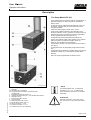
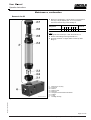
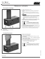
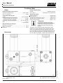
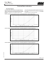
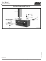
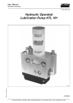
User Manual Operation Instructions 2.1EN-39007-B11 Hydraulically Operated Lubrication Pump HTL 201 B-H TL 201-0 00a10 Subject to modifications 810-53303-1B LINCOLN GmbH • Postfach 1263 • D-69183 Walldorf • Tel +49 (6227) 33-0 • Fax +49 (6227) 33-259 User Manual Operation Instructions 2.1EN-39007-B11 This User Manual was compiled on behalf of - the manufacturer - by Lincoln GmbH EdiDoc GmbH Heinrich-Hertz-Str. 2-8 Erzberger Str. 8 D-69190 Walldorf D-68753 Waghäusel All rights reserved. Any duplication of this User Manual, in its entirety or in part, by whatever means is prohibited without the prior consent in writing of Lincoln GmbH. Subject t o modifications without prior notif ication. Subject to modifications © 2011 by Phone: +49 (6227) 33-0 Fax: +49 (6227) 33-259 E-Mail: [email protected] Page 2 of 24 LINCOLN GmbH • Postfach 1263 • D-69183 Walldorf • Tel +49 (6227) 33-0 • Fax +49 (6227) 33-259 User Manual Operation Instructions 2.1EN-39007-B11 Table of Contents Page Introduction Explanat ion of Symbols Used................. ...................... ....... 4 User´s Responsibility....... ....................... ...................... ....... 4 Environmental Protection ....................... ...................... ....... 4 Service ...... ........ .............. ....................... ...................... ....... 4 Safety Instructions Appropriate Use .............. ....................... ...................... ....... 5 Misuse ....... ........ .............. ....................... ...................... ....... 5 Exclusion of Liability .. ....................... ...................... ....... 5 Accident Prevention Regulations............ ...................... ....... 5 General Safety Instructions .................... ...................... ....... 5 Operation, Maintenance and Repair....... ...................... ....... 5 Operation/Maintenance .................... ...................... ....... 5 Repairs ........ .............. ....................... ...................... ....... 6 Disposal ....... .............. ....................... ...................... ....... 6 Installation . ........ .............. ....................... ...................... ....... 6 Installation and Maintenance of Hydraulic Hoses .. ...... 6 Description The Pump Model HTL 201 .................... ...................... ...... 7 Page Maintenance Lubricant Cartridge .................. ...................... ............... .....10 Adapter ........ ...................... ............... ....... ............... .... 10 Filling of Reservoir .................. ...................... ............... .... 11 Operation with lubricant cartridge ............ ............... .... 11 Operation with press reservoir .......... ....... ............... .... 11 Reservoir for Oil ...................... ...................... ............... .... 13 First Insertion of Cartridge ....... ...................... ............... .....14 Cartridge Replacement ............ ...................... ............... .....14 Cleaning the Oil Strainer ......... ...................... ............... .... 15 Identification code ................ ...................... ............... .... 15 Technical Data Rating ............... ...................... ...................... ............... .... Dimensions ....... ...................... ...................... ............... .... Flow Rate Diagrams ............... ...................... ............... .... Hydraulic Circuit ...................... ...................... ............... .... 16 16 17 18 Troubleshooting .................... ............... ....... ............... .... 19 Exploded Drawing and Parts List .............. ............... .... 20 Working Method ........... ....................... ...................... ...... 8 EC Declaration of incorporation ................ ............... .... 23 Adjustment and Operation Basic Adjustment of the Throttle Valve... ...................... ....... 8 Pump Element... .............. ....................... ...................... ....... 9 Pressure Relief Valve ..... ....................... ...................... ...... 9 Lincoln worldwide ................. ...................... ............... .... 24 Subject to modifications For further informati on refer to: Installat ion Instructions for kit of seals 542-34079-1 2.0-30008-B08 Installat ion Instructions for hose stud 2.0-39000-A08 Page 3 of 24 LINCOLN GmbH • Postfach 1263 • D-69183 Walldorf • Tel +49 (6227) 33-0 • Fax +49 (6227) 33-259 User Manual Operation Instructions 2.1EN-39007-B11 Introduction Explanation of Symbols Used The following description standards are used in this manual: Safety Instructions Structure of safety instructions: Pictogram Signal word Danger text - Danger note - How to avoid danger The following pictograms are used in t his manual and are combined with the corresponding signal words: 1013 A94 4 273a0 0 - ATTENTION - CAUTION - ATTENTION - CAUTION - WARNING - WARNING 6001a 02 - NOTE - IMPORTANT The signal words give the seriousness of danger if the following text is not observed: ATTENTION CAUTION WARNING NOTE IMPORTANT refers to faults or damages on machines. refers to bad damages and possible injuries. refers to possible dangerous injuries. indicates improved operation of the device. indicates special operating features of the device. Example: User's Responsibility To ensure the safe operat ion of the unit, the user is responsible for the following: 1. The pump / system shall be operated only for the intended use (see next chapter "Saf ety Instructions") and its design shall neither be modified nor transformed. 2. The pump / system shall be operated only if it is in a proper functioning condition and if it is operated in accordance with the maintenance requirements. 3. The operating personnel must be familiar with this User Manual and the safety instructions mentioned within and observe these carefully. The correct installation and connection of tubes and hoses, if not specified by Lincoln GmbH, is the user's responsibility. Lincoln GmbH will gladly assist you with any questions pertaining to the installation. Environmental Protection Waste (e.g. used oil, detergents, lubricants) must be disposed of in accordance with relevant environmental regulations. Service The personnel responsible for t he handling of the pump / system must be suitably qualified. If required, Lincoln GmbH offers you full service in the form of advice, on-site installation assistance, training, etc. We will be pleased to inform you about our possibilities to support you purposefully. In the event of inquiries pertaining t o maintenance, repairs and spare parts, we require model specific data to enable us to clearly identify the components of your pump / system. Therefore, always indicate the part, model and series number of your pump / system. Subject to modifications 10 13A94 ATTENTION! When making use of other than the tested spare parts, serious damage may affect your device. Therefore, for the operation of your device always use original parts made by Lincoln GmbH. Furthermore, you will find the following text symbols in this manual: Listing of applicable statements - Subpoint of applicable statements 1. Determination of the number or sequence of contents  Procedural instruction Page 4 of 24 LINCOLN GmbH • Postfach 1263 • D-69183 Walldorf • Tel +49 (6227) 33-0 • Fax +49 (6227) 33-259 User Manual Operation Instructions 2.1EN-39007-B11 Safety Instructions General Safety Instructions Appropriate Use The hydraulically operated lubrication pump model HTL 201 is designed for initial or subsequent retrofit installation. It is designed for: 1. the automat ic lubrication of hydraulic hammers; 2. the automat ic lubrication of hydraulically driven units. The pump is able to deliver lubricants and chisel pastes up to NLGI-class 2 or oils from min. 40 mm²/s (cSt). Misuse Any use of the hydraulically operated lubrication pump HTL 201 that is not expressly mentioned in this User‘s Manual will be regarded as misuse. If the hydraulically operat ed lubrication pump HTL 201 is used or operated in a different manner other than specified, any claim for warranty or liability will be null and void. NOTE 6001a0 2 If personal injury or material damage occurs as a result of inappropriate operation, e.g. if the safety instructions are ignored or resulting from incorrect installation of the hydraulically operated lubrication pump HTL 201, no claims or legal actions may be taken against the manufacturer. Hydraulically operated lubrication pumps model HTL 201: - are designed with state-of-the-art technology. - can be mounted for safe operation Incorrect use may result in bearing damage caused by under- or over-lubrication. Modifications or alterations to an installed system by the customer are subject to prior consultation with the manufacturer of t he lubrication system or wit h its appointed dealers. Hydraulically operated lubrication pumps model HTL 201: - are not to be installed in the lower area of the hammer, - must be installed in such a way that the driver/ operator can always see the position of the low-level indicator of the follower piston. After each cartridge replacement make sure that the pump delivers lubricant. Operation, Maintenance and Repair ATTENTION! Before beginning with maintenance or repair work on the lubrication pump HTL 201, ensure that the hydraulic system of the carrier unit (t he supply to the lubrication pump) is depressurized. 1013A94 Exclusion of Liability ATTENTION! The manufacturer of the lubrication pump HTL 201 does not accept any liability for damages caused by: tardy replacement of the cartridges (lack of lubricant) poor lubrication due to air entrapments in the lubricant supply (e. g. after replacement of t he cartridge) use of lubricants that are inappropriate or only conditionally appropriate for the unit or which are not pumpable inappropriate disposal of used or contaminated lubricants arbitrary modification of system parts use of unauthorized spare parts and lubricant cartridges, including the usage of refilled cartridges wit h non- approved or contaminated lubricants (loss of waranty). It is absolutely forbidden to carry out maintenance or repair work and to replace the cartridge while the hydraulic unit is in operation. ATTENTION! A contamination of the oil strainer (fig. 4-11) can result in poor lubrication of connected lubrication points. Depressurize the carrier unit before disassembling the oil strainer. Subject to modifications Regulations for Prevention of Accidents To prevent accidents, observe all city, state and federal safety regulations of the country in which the product will be used. Avoid the operation with - unapproved parts. - insufficient or contaminated lubricants. 1013A94 CAUTION! Risk of injury in case of contact with hot connection parts or hot oil of the driving hydraulics. Let the driving hydraulics cool down before starting any maintenance or repair work to avoid burning or scalding or wear adequate protective clothes. Operati on / Maintenance Hydraulically operated lubrication pumps HTL 201 shall be operated only with an installed pressure relief valve shall regularly be supplied with clean lubricant cartridges. 150g/310g cartridges can’t be refilled. operate aut omatically. However, check at regular intervals (approx. every 2 days) whether the pump effectively delivers lubricant (visual check). Page 5 of 24 LINCOLN GmbH • Postfach 1263 • D-69183 Walldorf • Tel +49 (6227) 33-0 • Fax +49 (6227) 33-259 User Manual Operation Instructions 2.1EN-39007-B11 Safety Instructions, continuation Repair Disposal Repairs should only be performed by authorized personnel who are familiar with t he repair instructions. Dispose of used or contaminated lubricants as well as of parts that were in touch with lubricant according to the legal regulations pertaining to environmental protection. Make sure to observe the safety dat a sheets of the lubricants used. Installation ATTENTION! Before installing or disassembling the lubrication pump HTL 201, ensure that the hydraulic system of the carrier unit (the supply to the lubrication pump) is depressurized. Installation and Maintenance of Hydraulic Hoses ATTENTION! The operational safety of the lubrication pump HTL 201 is only guaranteed w ith a professional installation and maintenance of hydraulic hoses/lines. The following points must be observed! 10 13A94 It is forbidden to manipulate the protection devices installed on the hydraulic unit. If necessary, these devices may be removed temporarily during the installation of the pump. The devices must be properly put back in place after installation. Use only original spare parts or spare parts and cartridges authorized by Lincoln (see „Parts List“). IMPORTANT 6001a0 2 Observe the installation guidelines and instructions of t he machine/ unit manufacturer when drilling and welding, as well as the specified minimum distance on vehicle/chassis frames for holes between upper/lower rim of the frame or bet ween two bore holes. 1013A94 Hydraulic Hose/lines may never be subjected to torsion must be installed twist-free must not rub against metal components or edges are to undergo regular visual checks and exchanged in the case of wear (or at the latest, 2 years after installation) Pay attention with non linear installations to allow for as large a bending radius as possible. Kinks are to be avoided. In constricted installation condit ions use pipe elbow unions to avoid the danger of kinking behind the hose socket . IMPORTANT For fastening of the HTL 201 pump use cylindrical screws DIN 4762, M10x90. Subject to modifications 6001a0 2 Page 6 of 24 LINCOLN GmbH • Postfach 1263 • D-69183 Walldorf • Tel +49 (6227) 33-0 • Fax +49 (6227) 33-259 User Manual Operation Instructions 2.1EN-39007-B11 Description The Pump Model HTL 201 is a hydraulically driven grease pump for t he lubrication of hydraulic hammers or other units with an available hydraulic circuit. is compact and can therefore be fitted directly to the carrier device. Together with the carrier device it f orms a complete assembly. is driven by the hydraulic system of the carrier . continuously delivers lubricant to the lubrication point while the hydraulic unit is in operation and stops when the hydraulic flow st ops. The lubricant quantity is adjustable via the regulating throttle valve (see Fig. 4). is equipped with a visual lubricant level indicator by means of the follower plate of the cartridge. If the follower plate is located in the low-level position of the cartridge 2b, the cartridge must be replaced. is protected by means of a 120 bar pressure relief valve 7 (see Fig. 6). is equipped with an exchangeable pump-element pistonunit.. is equipped with a lubrication hydraulic fitt ing 4 for manual lubrication override (e.g. if the hydraulic system fails to operate). does not require supplementary directional valve. Subject to modifications B-HT L201-010f 10 Fig. 1-1 Components of the Lubrication Pump HTL 201 1 - Cartridge 1) 2a - Follower piston, cartridge full 2b - Low-level position (window) of the follower piston, cartridge empty 3 - Pump element, lubricant outlet, G ¼ 1 4 - Hydraulic lubrication fitting G /8, für manuelles Abschmieren 6 - Cartridge housing 7 - Pressure relief valve 120 bar 8 - Control housing 11 - Fastening holes for M 10 bolts 12 - Throttle below closure plug 12.1 13 - Return connection 1) T, G ¼ 14 - Pressure connection 1) P, G ¼ 15 - Cylinder screw M4 x 12 for bleeding 1) 6001 a02 NOTE Connecting fittings 13 & 14 and gease cartridges 1 are n o t included in t he scope of delivery and have to be ordered separately. ATTENTION! Pressure connection 14 (P) and returnline connection 13 (T) must not be mixed up. 1013 a94 Page 7 of 24 LINCOLN GmbH • Postfach 1263 • D-69183 Walldorf • Tel +49 (6227) 33-0 • Fax +49 (6227) 33-259 User Manual Operation Instructions 2.1EN-39007-B11 Mode of Operation HTL 201  The HTL 201 lubricat ion pump is connected by means of the following connecting fittings: 3 - Lubricant outlet, G ¼ 12.1 - Throttle below closure plug 13 - Return connection T, G ¼ 14 - Pressure connection P, G ¼ with integrated oil strainer 1) The f low rate and thus the output of the pump can be adapted according to the output diagram (fig. 6-1 t o 6-3) via t he regulating throttle valve 12. 16 notches of the regulating throttle correspond to one full revolution. The oil flows via the pressure connection 14 (resp. P) through an integrated strainer to the control piston. In parallel, the also activated supply piston moves a premetered amount of lubricant to the lubricant outlet 3. The oil is returned to the driving system of the carrier unit via t he relief line connection 13 (resp. T) 1) . incl. check valve B-HT L201 -020 a10 Fig. 2-1 Hydraulic oil connections of the lubrication pump HTL 201 Setting and Operation Basic Adjustment of the Throttle  Remove closure plug 12.1 (Fig. 2-1) of the throttle 9.  The throttle 9 is factory-set to grid 80 (see Flow Rate Diagrams fig. 6-1 to 6-3).  Turn the thrott le screw 9 according to the lubricant requirement: - turning clockwise (–) ………………….…. .. less lubricant - turning anticlockwise (+) ………………… more lubricant  Close closure plug 12.1 of throttle 9 again to protect throttle against contamination. IMPORTANT Observe the specified lubricant quantities (see Fig. 6-1 to 6-3). 60 01a02 1013 A9 4 B-HTL201 -030 a10 Fig. 3-1 Throttle Valve Adjustment To adjust the throttle, stop the hydraulic system operation. The throttle may still be pressurized for a long time after switching off the hydraulic unit. Always check first whether the pressure connection 14 (P, fig. 2-1) is depressurized. 9 - Throttle valve Page 8 of 24 LINCOLN GmbH • Postfach 1263 • D-69183 Walldorf • Tel +49 (6227) 33-0 • Fax +49 (6227) 33-259 Subject to modifications ATTENTION! User Manual Operation Instructions 2.1EN-39007-B11 Setting and Operation, continuation Pump element During the operation the piston 3.2 (Fig. 3-2) sucks in lubricant from the cartridge via the suction bore hole 3.1 and delivers it to the connect ed lubrication point through the lubricant outlet 3.3. An integrated check valve prevents the lubricant from returning t o the cartridge. Piston diameter . ...................... ............... ....... ............... . 7 mm Lubricant output ...................... ......... approx. 0.22 ccm/stroke B-H TL 201-020b10 Fig. 3-2 Pump element (Pos. 3) 3.1 - Suction bore 3.2 - Piston 3.3 - Lubricant outlet, G ¼ Pressure Relief Valve B-HTL201 -020 c10 Fig. 3-3 The pressure relief valve limits the pressure build-up in the system. opens when a pressure of 120 bar is reached. Alternat ively, in the case of higher supply pressure a pressure-relief valve for a max. overpressure of 270 bar can be used. Pressure Relief Valve (pos. 7) NOTE If lubricant is expelled at the pressure relief valve, this indicates that there is a blockage to, or at the lubrication point. 6001 a02 IMPORTANT Subject to modifications When using chisel pastes, the outlet pressure P must not exceed 100 bar. Page 9 of 24 LINCOLN GmbH • Postfach 1263 • D-69183 Walldorf • Tel +49 (6227) 33-0 • Fax +49 (6227) 33-259 User Manual Operation Instructions 2.1EN-39007-B11 Maintenance 10 13A94 CAUTION! ATTENTION! Risk of injury in case of contact with hot connection parts or hot oil of the driving hydraulics. Let the driving hydraulics cool down before starting any maintenance or repair work to avoid burning or scalding or wear adequate protective clothes. Do not perform any maintenance or repair work or replace the cartridge while the hydraulic system of the carrier device is in operation. ATTENTION! 1013A94 Before beginning with maintenance or repair work on the lubrication pump HTL 201 and before dismantling it, ensure that the hydraulic system of the carrier device is depressurized. Lubricant Cartridge Capacity ................. ............... ...................... .... 150 g / 310 g Lubricant ................ ............... ................. up to NLGI class 2 NOTE Cartridges are n o t included in the scope of delivery and must be ordered separately. 600 1a02 6007h 07 Fig. 4-1 IMPORTANT Never try to refill emptied cartridges! After use dispose of emptied cartridges according to the legal regulations pertaining to environmental protection. 1 - Cartridge 1.1 - Follower plate 1.2 - Tip of thread throat Lubricant Cartridge Adapter  Before the replacement or first insertion of a 380 g, 400 gor 500 g- cartridge, an adapter (Fig. 4-2) must be mounted to the housing of the cartridge 6 (Fig. 1-1). Positions (Fig. 4-2) Designation 2.1 2.2 2.3 2.4 2.5 2.6 2.7 Adapter 380 g 1 ), TR (Trapezoidal thread) Kit of seals x 1 ) & 2) x x x x x x x x x Part no. 542-33136-1 542-34079-1 1) Adapter 400 g , RD (Round thread) x x x x x 542-33133-1 x 542-33135-1 3) Adapter 500 g , TR (Trapezoidal thread) 2) 3) B-HT L201 -040 b08 Fig. 4-2 x x for 380 g-lubricant cartridges see Installation Instructions 2.0L-30008-B08/part no. 810-55488-1 for 500 g lubricant cartridges 2.7 2.6 2.5 2.4 2.3 2.2 2.1 - Hexagonal socket head screws M5x35 - Flat packing NBR - Sealing ring PU90 - Adapter - O ring NBR - O ring NBR - Tubular support Adapter for lubricant cartridges Page 10 of 24 LINCOLN GmbH • Postfach 1263 • D-69183 Walldorf • Tel +49 (6227) 33-0 • Fax +49 (6227) 33-259 Subject to modifications 1) x User Manual Operation Instructions 2.1EN-39007-B11 Maintenance, continuation Filling of Reservoir Operation with lubricant cartridge  Replace the emptied lubricant cartridge (150 g / 310 g) as soon as its follower piston has sunk down to the cartridge housing 6. NOTE Cartridges (150 g/310 g; 380 g) are not included in the scope of delivery, but have to be ordered separately. 6001a 02 IMPORTANT Dispose of emptied cartridges according to the legal regulations pertaining t o environmental protection. Operation with press container  Fill the press container with lubricant (or with a 380 g lubricant cartridge as soon as the hand lever 1.1 has sunk as shown in Fig. 4-3. B-HTL20 1-04 0g10 Fig. 4-3 1- Subject to modifications 234615 - F illing-level control of the press container Press container 1.1 - Hand lever 1.2 – Closure cap 1.3 - Spring 1.4 – Follower piston Adapter Pump el ement – lubricant outlet, G ¼ Hydraulic lubrication fitting G 1 /8, for manual l ubrication Cartridge housing Cylinder screws M4 x 12 for bleeding Page 11 of 24 LINCOLN GmbH • Postfach 1263 • D-69183 Walldorf • Tel +49 (6227) 33-0 • Fax +49 (6227) 33-259 User Manual Operation Instructions 2.1EN-39007-B11 Maintenance, continuation Operation wi th press reservoir, continuation - Adjust filling variant: B-MGP101 -02 0b10  Unscrew the reservoir (grease gun) from the housing of the HTL.  Check the follower piston packing and adjust it if necessary: 1. 2. For cart ridge (400 g) Fig. 4-4 For bulk grease filling Adjustment of the follower piston packing 3. 4. 5. Unscrew reservoir closure cap. Pull the follower rod together with the spring and the follower piston out of the press reservoir by means of the hand lever. Evert packing of follower piston (see Fig. 4-4) Proceed with re-assembly of follower piston. Screw closure cap to press reservoir again. Filling - Operation with lubricant cartridge (150 / 310 g): - Operation with bulk grease filling in press reservoir: (without press reservoir)  If required, remove empt y cartridge 1. Cut off cone point of the t hread throat of the new cartridge. 2. Push follower piston into the cartridge pressing it lightly until grease leaks from the open thread throat. 3. Insert cartridge with light pressure into the bore of the HTL housing and hand-tighten it. 4. Remove trapped air, if any (see chapter “Vent housing”).  For initial filling with bulk grease filling adapt filling variant, if necessary (see Fig. 4-4). 1. Remove grease reservoir fittings from the HTL adapter. 2. Immerge the open end of the press reservoir into the grease container. Slowly pull the hand lever backwards while following the sinking filling level in the grease container. This will prevent air from being sucked into the press reservoir during the filling procedure (Fig. 4-6). B-MGP101- 020d1 0 B-MG P101- 020 e10 - Operation with lubricant cartridge (400 g): (with press reservoir) 1. Remove grease reservoir fittings from the HTL adapter. 2. Pull back the follower rod together with the follower piston by means of the hand lever from the press reservoir to that extent that the nut in the follower rod engages in the notch of the reservoir’s closure cap. Fig. 4-6 Fig. 4-5 3.  4. 5. 6. 7. Engaging of the follower rod B-MGP101-020c10 Use the hand lever to carefully unlock the follower rod and let it return into the press reservoir thus discharging the empty cartridge. For initial filling with 400g lubricant cartridge adapt filling variant, if necessary (see Fig. 4-4). Remove plastic sealing cover (B.1) from grease cartridge (B) and push cartridge with that side into the press reservoir (A). Remove tear-off lid (B.2) from the grease cartridge and then screw the grease reservoir fittings to the HTL adapter. Unlock the f ollower rod f rom the reservoir’s closure cap. Remove trapped air, if any (see chapter “Vent housing”). 4. 5. 6. Fig. 4-7 Engaging Pull back the follower rod together with the follower piston by means of the hand lever from the press reservoir to that extent that the nut in the follower rod becomes visible and engages in the notch of the reservoir’s closure cap (Fig. 4-7). Screw the filled press reservoir again. Disengage the follower rod from the reservoir’s closure cap by means of the hand lever. Remove trapped air, if any (see Chapter “Vent housing”). CAUTION! Risk of injury by unwant ed resilience of follower rod. If engaged inaccurately (Fig. 4-6) the follower rod may unlatch unwantedly. Make sure the latching function works 1013A9 4 properly and prevent unintended unlatching. Page 12 of 24 LINCOLN GmbH • Postfach 1263 • D-69183 Walldorf • Tel +49 (6227) 33-0 • Fax +49 (6227) 33-259 Subject to modifications 3. Suction User Manual Operation Instructions 2.1EN-39007-B11 Maintenance, continuation Reservoir for Oil  Before the replacement or first insertion of a reservoir for oil 2 (Fig. 4-8) an adapter (pos. 2.1 to 2.3) must be mounted to the housing of the cartridge 6. Designation Reservoir for oil Position 2 (Fig. 4-8) 2.1 2.2 2.3 2.4 2.5 2.6 2.7 x x x x x x x Part no. 542-33134-1 Filling:  Untighten the screw top 2.7 from the reservoir 2.4.  Fill in the lubricating oil through the filter 2.6.  Close the reservoir 2.4 again with the screw top after filling 2.7. B-HT L201-040c10 - Reservoir for oil, assy. - Screw top - Strainer - Strainer insert - Reservoir - Hexagonal socket head screws M5x25 - Adapter - O-ring - Cartridge housing Res ervoir for oil, assy. Subject to modifications Fig. 4-8 2 2.7 2.6 2.5 2.4 2.3 2.2 2.1 6 Page 13 of 24 LINCOLN GmbH • Postfach 1263 • D-69183 Walldorf • Tel +49 (6227) 33-0 • Fax +49 (6227) 33-259 User Manual Operation Instructions 2.1EN-39007-B11 Maintenance, continuation First insertion of cartridge  Lightly grease the inner o-ring.  Cut off tip of thread throat 1. 2 (Fig. 4-1) of the new cartridge.  Insert the cartridge in the bore by lightly pressing and screw it into the housing (presented as in Fig. 4-9) handtightly.  Vent housing: - Remove cylinder head screw 15 from front or rear side - Press follower piston 1.1 (Fig. 4-1) into the cartridge until lubricant comes out of the open bore hole 15 - Close housing with cylinder head screw 15 (Fig. 4-9) again  Operate the pump by swit ching on the hydraulic unit until lubricant flows out of the opened pump element 3. NOTE The pump delivers lubricant very slowly. It may take a while before t he lubricant flows out of the outlet without air bubbles. 600 1a02 B-HT L201 -040 d10 Fig. 4-9  Connect the supply hose (primed where applicable) to the lubrication point with pump element 3.  Manual lubrication is possible via the hydraulic lubrication fitting 4 by means of a manually operated grease gun. Insert cartridge into the lubrication pump HTL 201 3 - Pump element 4 - Lubrication fitting for manual lubrication 15 - Cylinder head screw Cartridge Replacement  Switch off the carrier device.  Unscrew the old cartridge.  Cut off the point of the thread throat 1.2 (Fig. 4-1) of the new cartridge.  Press the follower piston 1.1 (Fig. 4-1) slightly until grease comes out of the cart ridge.  Press cartridge slight ly into the cartridge, t he screw it into the housing hand-tightly (as shown in Fig. 4-10). - The pump is ready for operation again NOTE If afterwards the pump does not dispense lubricant immediately, vent the housing (see paragraph "vent housing", Fig. 4-9). B-HT L201-040e 10 Fig. 4-10 Cartridge Replacement Page 14 of 24 LINCOLN GmbH • Postfach 1263 • D-69183 Walldorf • Tel +49 (6227) 33-0 • Fax +49 (6227) 33-259 Subject to modifications 600 1a02 User Manual Operation Instructions 2.1EN-39007-B11 Maintenance, continuation Cleaning the Oil Strainer The oil strainer should be cleaned every 1000 operating hours at the latest. To do this, proceed as follows:  Completely relieve pressure of hydraulic system on carrier device.  Remove the pressure line to the lubrication pump HTL 201.  Oil Strainer 14.1 (Fig. 4-11) - Unscrew oil strainer 14.1 (Fig. 4-11) from control housing 8. - Remove and clean oil strainer. - Screw oil strainer back into the control housing 8 again Fig. 4-11 B-H TL 201-040f10 Oil Strainer in the control housing 8 - Control housi ng 14 - Pressure connection P, G ¼ 14.1 - Oil Strainer Identification Code Example of a type designation HTL - 2 01 - C7 HTL - 2 01 - K7 HTL Hydraulic Tool Lubrication Version (type series) Applic ation Number of pump elements C7 = K7 = Piston diameter 7 mm for chisel paste (increased fit-tolerance) Piston diameter 7 mm for grease NOTE Part numbers see “Parts List”. Subject to modifications 6001a0 2 Page 15 of 24 LINCOLN GmbH • Postfach 1263 • D-69183 Walldorf • Tel +49 (6227) 33-0 • Fax +49 (6227) 33-259 User Manual Operation Instructions 2.1EN-39007-B11 Technical Data Rating Factory Output Settings Hydraulic input pressure P ............ .................... 80 to 210 bar min. run-in pressure ....... ............... ....................... ....... 30 bar Lubrication Pump HTL 201 Output ....... ...................... ............... ................ 0.22 ccm/stroke max. operating pressure (lubricant): - D Pressure relief valve, standard ....................... ...... 120 bar - Pressure relief valve, optionally ... ....................... ...... 270 bar Admissible operating temperature 1) .......... –25 °C to +75 °C 2) Ratio ......... ...................... ............... ....................... ......... 50 : 1 2) Oil temperature Standard Fitting Connections Pressure connection P .................. ....................... .......... G ¼“ Return connection T ....... ............... ....................... .......... G ¼“ Feed line.... ...................... ............... ....................... .......... G ¼“ Dimensions Thrott le ..................... ............... ............... completely opened max. output .............. .............. depending on input pressure P Tightening Torques Hydraulic fitting (4) ... ............... ...................... .... 14 Nm ± 5 % Valve insert (7) ......... ............... ...................... .... 8 Nm ± 10 % Cylinder head screws M4 x 12 (15) ............... .... 3 Nm ± 10 % Cylinder head screws M8 x 80 (9) ................. .. 15 Nm ± 10 % Fixing screws M10x90 ............ ...................... .. 70 Nm – 10 % 1) IMPORTANT The specified “admissible operating temperature” refers to t he pump and the components of the entire lubrication system, but not to the lubricant to be 6001 a02 supplied. Therefore, please observe that the transportation of the lubricant in a system depends on t he lubricant’s flow properties. The “admissible operating temperature of the lubricant” may differ from t he system operating temperature and has to be verified separately! For applicable lubricants also see User Manual 2.0-40001, chapt er “Approved lubricants”. 6566 h08 Fig. 5-1 Dimensions of the Hydraulic Lubrication Pump HTL 201 with cartridge (all dimensions in mm) A: Height 194 mm with 150 g cartridge B: Height 286 mm with 310 g cartridge Page 16 of 24 LINCOLN GmbH • Postfach 1263 • D-69183 Walldorf • Tel +49 (6227) 33-0 • Fax +49 (6227) 33-259 Subject to modifications Hydraulic system (Carrier device): User Manual Operation Instructions 2.1EN-39007-B11 Technical Data, continuation Flow Rate Diagram Output ccm/min The output results from the t hrottle revolutions and the use of The lubricant flow rate as a function of the thrott le setting at the use of a pump element with an output of 0.22 ccm/stroke. different pressures can be read from the following flow rate Max. output ..... .............. ....................... ............... 6.7 ccm/min diagram. The throttle valve is provided with notches, whereby (at 200 bar and max. opening of throttle) 16 notches correspond to one complete revolution of the throttle. Lubricant Output HTL 201 (at 80 bar and 40 °C operating temperature, 100 bar back-pressure) B-H TL 201050 b10 – close < < < Fig. 6-1 Throttling (by means of notches) > > > open + Flow rate diagram at 80 bar (averaged curve progression) Output ccm/min Lubricant Output HTL 201 (at 140 bar and 40 °C operating temperature, 100 bar back-pressure) B-HT L201-050c10 – close < < < Fig. 6-2 Throttling (by means of notches) > > > open + Flow rate diagram at 140 bar (averaged curve progression) Subject to modifications Output ccm/ min Lubricant Output HTL 201 (at 200 bar and 40 °C operating temperature, 100 bar back-pressure) B-HTL201 -050 d10 – close < < < Fig. 6-3 Throttling (by means of notches) > > > open + Flow rate diagram at 200 bar (averaged curve progression) Page 17 of 24 LINCOLN GmbH • Postfach 1263 • D-69183 Walldorf • Tel +49 (6227) 33-0 • Fax +49 (6227) 33-259 User Manual Operation Instructions 2.1EN-39007-B11 Technical Data, continuation Hydraulic Circuit B-HT L201 -050a 10 2 - Oil strainer 5 - Rearrangement pi ston R - Return connection (T) 3 - Lubricant outlet 6 - ressure relief valve 120 bar Subject to modifications Fig. 7-1 Hydraulic Circui t HTL 201 1 - Mechanical pump (pump element) 4 - T hrottle, adjustable P - Pressure connection Page 18 of 24 LINCOLN GmbH • Postfach 1263 • D-69183 Walldorf • Tel +49 (6227) 33-0 • Fax +49 (6227) 33-259 User Manual Operation Instructions 2.1EN-39007-B11 Troubleshooting Fault: Pump does not deliver the lubricant Cause: Remedy … by operator personnel Cartridge empty  Replace the cartridge (see Fig. 4-10). Lubricant supply blocked  Check the cartridge. Air entrapments in the suction area of the cartridge  Vent housing (see Fig. 4-9) „First Insertion of cartridge“. Cause: Remedy … by service personnel No oil pressure supply  Check the hydraulic system and repair it.  Check the tube and hose lines and replace them. Clogged oil strainer  Fully relieve pressure of hydraulic system on carrier unit.  Clean oil strainer (see Fig. 4-11). Fault: Lubricant quantity too low Cause: Remedy … by service personnel Throttle not adjust ed correctly  Turn the throttle anticlockwise by 1 to 2 notches (more lubricant will flow out); see Fig. 3-1. Clogged oil strainer  Fully relieve pressure of hydraulic system on carrier unit.  Clean oil strainer (see Fig. 4-11). Fault: Lubricant quantity too high Cause: Remedy …  Turn the throttle clockwise by 1 to 2 notches (less lubricant will flow out); see Fig. 3-1. Throttle not adjust ed correctly by service personnel Fault: Lubricant leaking at the cartridge inlet Cause: Remedy …  Check the sealing ring in the pump unit and replace it if necessary  Check whether the cartridge is threaded correctly (handtight seat). Leakage by service personnel Fault: Lubricant leaking at the grease outlet Cause: Remedy …  Check the fittings and retighten them if necessary. Leakage by service personnel Fault: Oil pressure leaking at the hydraulic system Cause: Remedy …  Check the fittings and retighten them if necessary. Leakage by service personnel Subject to modifications Fault: Lubricant leaking at the pressure relief valve Cause: Remedy … Blockage in lubricant f eed line or at lube point  Check the lubricant feed lines and the lube points for possible causes of blockage. Backpressure in the feed lines too high  Check whether the standard pressure relief valve (120 bar) is sufficient. If necessary, use the optional pressure relief valve with 270 bar. Tab. 1 by service personnel Troubleshooting Page 19 of 24 LINCOLN GmbH • Postfach 1263 • D-69183 Walldorf • Tel +49 (6227) 33-0 • Fax +49 (6227) 33-259 User Manual Operation Instructions 2.1EN-39007-B11 Exploded Drawing and Parts List B-HT L20 1-070 a10 Exploded Drawing and Parts List Subject to modifications Fig. 8-1 Page 20 of 24 LINCOLN GmbH • Postfach 1263 • D-69183 Walldorf • Tel +49 (6227) 33-0 • Fax +49 (6227) 33-259 User Manual Operation Instructions 2.1EN-39007-B11 Exploded Drawing and Parts List, continuation Parts List Pos. Description 1 Pos. Description Qty. Part-Number HTL 201 with pump element C7 1 642-41184-1 HTL 201 with pump element K7 1 642-41184-2 Cartridge wit h chisel paste, 150 g 12 642-37608-4 7 Qty. Part-Number Pressure relief valve 120 bar Pressure relief valve 270 bar (opt ionally) 1 235-14343-5 1 235-14343-2 9 Cylinder head screw M8 x 80 4 201-10431-7 1 442-72445-1 Cartridge wit h EP 2 gease, 150 g 12 642-37609-3 12 Closure plug M20 x 1,5 for throttle Cartridge wit h, 310 g 12 642-37636-2 14 Oil strainer, assy. 1 447-72394-1 Cartridge wit h EP 2 gease, 310 g 12 642-37609-4 15 Cylinder head screw 8.8 M4 x 12 3 201-12015-9 1.1 Gasket for cartridge 1 219-10555-1 Threaded packing GM1000 M4 3 220-14101-3 4 Hydraulic fitting 1/8 " 1 251-14109-6 Plug TL-4-119 D11,9 4 233-13100-2 17 Tab. 3 Parts List NOTE Connecting fittingsand cartridges are n o t included in the scope of delivery and must be ordered separately. 6001a 02 Accessories Pos. Descripti on Qty. Part Number Adapter kit for 380 g cartridge, trapezoidal thread TR 22 x 2, 75 (see Fig. 4-2) 1 542-33136-1 Kit of seals for 380 g cartridge TR (see Fig. 4-2) 1 542-34079-1 Adapter kit for 400 g cartridge, round thread RD 15 x 2,5 (see Fig. 4-2) 1 542-33133-1 Adapter kit for 500 g cartridge, trapezoidal thread TR 20 x 2, 5 (see Fig. 4-2) 1 542-33135-1 Reservoir for oil incl. strainer and adapter kit (see Fig. 4-8) 1 542-33134-1 Reservoir, transparent incl. adapter (see Fig. 4-2) 1 542-33430-1 Reservoir, steel incl. adapter (see Fig. 4-2) 1 542-33472-1 Accessories Subject to modifications Tab. 4 Page 21 of 24 LINCOLN GmbH • Postfach 1263 • D-69183 Walldorf • Tel +49 (6227) 33-0 • Fax +49 (6227) 33-259 User Manual Operation Instructions 2.1EN-39007-B11 Subject to modifications Notes: Page 22 of 24 LINCOLN GmbH • Postfach 1263 • D-69183 Walldorf • Tel +49 (6227) 33-0 • Fax +49 (6227) 33-259 User Manual Operation Instructions 2.1EN-39007-B11 Original Language D GB F E I EG- Einbau erklärung EC Declaration of incorporation D éclaratio n CE d 'inco rporation Declaración CE de incorporación Dich iarazione CE di in corporazio ne Hiermit erklären wir, dass die Bauart von Herewith we declare that the model of Par la présente, nous déclarons que le produit ci-dessous Por la presente, declaramos que el modelo suministrado Si dichiara che il prodotto da noi fornito en la versión suministrada es destinada a ser incorporada en una máquina y que su puesta en servicio está prohibida antes de que la máquina en la que vaya a ser incorporada haya sido declarada conforme a las disposiciones de los requisitos pertinentes y fundamentales de salud y seguridad en su redacción vigente en el momento de instalación. El fabricante se obliga a hacer disponible documentos técnicos (según anexo VII parte B) en versión imprimida a entes uniestatales a petición fundada referente al producto arriba mencionado. nella versione da noi fornita è destinato all’installazione in una macchina e che la relativa messa in esercizio resta vietata fino all’avvenuto accertamento della conformità della macchina nella quale il suddetto prodotto deve essere installato con tutti i requisiti basilari prescritti in termini di sicurezza e di salute, incluse le relativ e modifiche vigenti al momento della dichiarazione. Il costruttore si impegna a mettere a disposizione la documentazione tecnica (ai sensi dell’Allegato VII partel B) in forma scritta relativa al summenzionato prodotto dietro richiesta motivata presso le singole sedi nazionali. Norme armonizzate applicate in particolare: HTL 201 in der von uns gelieferten Ausführung zum Einbau in eine Maschine bestimmt ist und dass ihre Inbetriebnahme solange untersagt ist, bis festgestellt wurde, dass die Maschine, in die das o. g. Produkt eingebaut werden soll, den Bestimmungen aller einschlägigen grundlegenden Sicherheits- und Gesundheit sanforderungen entspricht, einschließlich deren zum Zeitpunkt der Erklärung gelt enden Änderungen. Der Hersteller verpflichtet sich, technische Dokumente (gem. Anhang VII Teil B) bei begründeter Anfrage zum o. g. Produkt einzelstaatlichen Stellen in gedruckter Form zur Verfügung zu stellen. Angewendete harmonisierte Normen, insbesondere: Maschin enrichtlinie 2006/42/EG in the supplied version is intended to be incorporated into machinery and must not be put into service until the machinery into which it is to be incorporated has been declared in conformity with the provisions of the relevant fundamental requirements on health and safety, including all modifications of this directive valid at the time of the declaration. The manufacturer undertakes to make available any technical documents in printed version (following Annex VII Part B) to subnational authorities in the case of reasonable request regarding the above mentioned product. Applied harmonized standards in particular: Machinery Directive 2006/42/EC DIN EN ISO 12100 – Teil 1 & 2 – Part 1 & 2 dans la version dans laquelle nous le livrons, est destiné à être installé sur une machine et que sa mise en service est interdite tant qu’il n’aura pas été constaté que la machine sur laquelle le produit mentionné ci-dessus doit être installé est conforme aux réglementations régissant toutes les exigences fondamentales de sécurité et celles relatives à la santé, y compris les amendements en vigueur au moment de la présente déclaration. Le fabricant s’engage, en cas de demande justifiée, à fournir sous forme écrite aux organismes nationaux respectifs les documents techniques (suiv ant Annexe VII, Partie B) relatifs au produit ci-dessus. Normes harmonisées, notamment : Directive machines 2006/42/CE – Parties 1 & 2 Normas armonizadas utilizadas, particularmente: Directiva de máquinas 2006/42/CE – Parte 1 & 2 Direttiva Macchine 2006/42/CE – Parte 1 e 2 Sicherheit von Maschinen Safety of machinery Sécurité de machines Seguridad de máquinas Sicurezza delle macchine Grundbegriffe, allgemeine Gestaltungsleitsätze Basic terms, general design guidelines Notions fondamentales, directives générales d’élaboration Términos básicos, axiomas generales de diseño Concetti basilari, principi guida generali Pumpen und Pumpen geräte für Flüssigkeiten Allgemeine sicherungstechnische Anforderungen Pumps and pump units for liquids DIN EN 908 Pompes et grou pes de pompes p our liquides Exigences en matière de sécurit é technique Bombas y equipos de bombas para líquidos Prescripci ones generales referente a la seguridad Pompe e dispositivi di pompag gio per liquidi Requisiti generali di sicurezza tecnica Responsable du Service de documentation Encargado/a de la documentación Responsabile della do cumentazione Doku mentationsb evollmächtigter General safety requirements Documentation agent Wolfgang Studer • Heinrich-Hertz-Str. 2-8 • 69190 Walldorf Lincoln Gm bH Heinrich-Hertz-Str. 2-8 D-69190 Walldorf Subject to modifications Walldorf Oct 12, 2010, ppa. Dr.-Ing. Z. Paluncic Director Research & Development Page 23 of 24 LINCOLN GmbH • Postfach 1263 • D-69183 Walldorf • Tel +49 (6227) 33-0 • Fax +49 (6227) 33-259 User Manual Operation Instructions Lincoln’s Global Distribution and Service Network – The Best in Our Industry – Whatever service is required – selecting a lubricating system, customised system installation or t he supply of top qualit y products – you will always be best advised by the staff of the Lincoln offices, representatives and contract dealers. Systems dealers Our systems dealers have the most extensive specialised knowledge in our industry. They plan your installations t o suit your specifications with exactly the combination of Lincoln components that you need. They then build the installations at your operat ion with experienced technicians or work closely wit h your personnel to ensure that everything goes smoothly. All dealers have the complete range of pumps, distributers, monitoring devices and accessories in stock and meet our exact ing demands with their specialised knowledge about products, installations and service. Whenever and wherever you need our experts, from St. Louis to Singapore, Walldorf and worldwide, Lincoln’s first-class systems dealers are at your service. Find out where the nearest Lincoln distribution and service office to you is located: Americas: Lincoln Industrial One Lincoln Way St . Louis, MO 63120-1578 USA Phone: (+1) 314 679 4200 Fax: (+1) 800 424 5359 Home: www.lincolnindustrial.com Europe/Africa/Asia: Lincoln GmbH Phone: (+49) 6227 33-0 Fax: (+49) 6227 33-259 E-Mail: [email protected] Asia/Australia/Pacific: Lincoln Industrial 3 Tampines Central 1 Corporation # 04-05 Abacus Plaza Singapore 529540 Heinrich-Hertz Straße 2-8 69190 Walldorf Germany © Copyright 2011 Phone: (+65) 6588-0188 Fax: (+65) 6588-3438 E-Mail: [email protected] D IN EN ISO 9001 by DQS R eg.-Nr. 799 D IN EN ISO 1 4001 by G UT