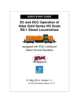
1
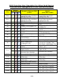
DC and DCC Operation
of Atlas Gold Series
Diesel Locomotives
Equipped with QSI Sound-Decoders
(Quantum™, Quantum Titan™, or
Quantum Titan™ with ET)
27 November 2013
Quick Start Revision 1.7
for Quantum Firmware Versions 7, 8, and 9
Quick Start Guide: DC and DCC Operation
Of Atlas Gold Series Diesel Locomotives
Equipped with QSI Sound-Decoders
(Quantum, Quantum Titan, or Quantum
Titan with ET)
Congratulations on purchasing an Atlas HO-scale or 2-rail O-scale Gold
Series sound-equipped locomotive that has a QSI sound decoder (Quantum,
Quantum Titan, or Quantum Titan with ET). The information in this section is
designed to help you get your new Atlas HO or 2-rail O-scale Gold Series
locomotive with QSI sound running on your layout as quickly as possible.
Atlas recommends that you get used to operating your new Atlas soundequipped diesel locomotive before exploring its more advanced features and
programming options.
The documentation for Atlas Gold Series HO-scale and 2-rail O-scale diesel
locomotives that are equipped with QSI sound decoders (Quantum, Quantum
Titan, or Quantum Titan with ET) is divided into three parts, with an increasing
level of detail included in each successive layer of the documentation:
•
Basic-Level Information: This document, the Quick Start Guide,
explains how to run a Gold Series locomotive on your layout and
operate a few basic functions such as
- Blowing the Horn
- Ringing the Bell
- Turning on and off the headlights: DCC (or DC with a
Quantum Engineer)
- Turning on and off the sound: DCC (or DC with a Quantum
Engineer)
Since it is essential that each DCC-equipped locomotive have a
unique address, information on programming a new DCC address is
included in the DCC section of this Quick Start Guide.
•
Intermediate Level Information: The document:
User Manual: DC and DCC Operation of Atlas Gold Series Diesel
Locomotives Equipped with QSI Sound-Decoders (Quantum™,
[1]
Quantum Titan™, or Quantum Titan™ with ET)
may be downloaded from the Atlas website: http://www.atlasrr.com/
by clicking first on the Support button and then on the DCC Support
button on the Atlas homepage. The User Manual explains, in
considerably more than the material in this document, how to:
2/24
-
Operate and program your Atlas Gold Series diesel
locomotive on a DC-powered layout,
- Use the (non-programming-related) functionality available in
your Atlas Gold Series diesel locomotive on a DCC–powered
layout,
- Program a number of commonly-used DCC Configuration
Variables (CVs).
Since the User Manual is written at a somewhat higher level than this
Quick Start Guide, Atlas recommends that you practice doing the
operations described in this Quick Start Guide before reading the
User Manual. Although the User Manual contains all the information
that many people will ever need to operate their locomotive, QSI
sound decoders (Quantum, Quantum Titan, or Quantum Titan with
ET) have many more capabilities than can be described in a
moderate-length document, such as the User Manual. If you wish to
take advantage of any of these advanced capabilities, please
download from the QSI Solutions website one of the two documents
(analog or DCC, as appropriate) listed in the next bullet item.
•
Advanced-Level Information: Advanced level information explains
in detail how to use all the operational and programming functionality
built into your Gold Series locomotive. Advanced-level information is
contained in two separate on-line documents, one for DC operation
and the other for DCC operation::
[2]
- DC: Quantum Analog Reference Manual Ver 4.0 (or later) ,
-
DCC: NMRA DCC Reference Manual for QSI Quantum 3, 2,
and 1 Equipped Locomotives, Version 5.1.0, February 4,
[3]
2013 (or later) .
Although intended primarily for advanced users, some of the
information in the above two documents will also be useful for
beginners or intermediate users who want to modify the behavior of
their locomotive in ways beyond the scope of the User Manual.
This document contains two Quick Start Guides: one for DC operation
(starting on page 4) and the other for DCC operation (starting on page 8).
Read the Quick Start Guide for the type of track power (DC or DCC) used on
your layout.
In addition, at the end of this document, there are procedures for:
• Resetting the QSI sound-decoder using the magnetic wand,
• Adjusting the overall sound system volume using the magnetic wand.
The two magnetic wand procedures listed above may be used in either DC or
DCC operation.
3/24
Quick Start Guide for DC Operation
If you have a DC-powered layout, read through this section and be up and
running with your new Gold Series locomotive in fewer than five minutes.
Controlling Speed and Direction of Gold Series
Locomotives on DC
Sound-equipped locomotives, such as Atlas Gold Series locos, behave
differently on a DC-powered layout from the way non-sound-equipped
locomotives operate. If you haven’t run sound-equipped locomotives on DC
before, the following two sections explain what to expect.
•
Running the Locomotive on a DC Layout
-
-
-
-
Use a variable voltage DC power pack with a standard
direction switch.
Set the direction switch to run your locomotive forward
Turn the throttle up slowly until you hear the Quantum
System™ begin to generate locomotive sounds. You will
have to move the throttle to a higher setting (about 4.5 volts)
than you would need to start a non-sound locomotive moving
just to get any sound from the Quantum System.
The sound-equipped locomotive will not start to move until
the track voltage exceeds 8.5 volts. At DC track voltages
between 4.5 and 8.5 volts, you will hear Start Up sounds, and
the Front and Rear Headlights will turn On in their Dim states.
(The Rear Headlight will be Off instead of Dim if your loco has
Version 7 firmware and Q1a hardware.) Continue to turn up
the throttle voltage (to about 9 volts) until the locomotive
begins to move forward. The directional Front Headlight will
turn from Dim to Bright, and locomotive sounds will continue.
The locomotive will start moving slowly due to special
Quantum inertia effects that resist rapid increases or
1
decreases in speed .
As you slow the locomotive down by gradually reducing the
throttle, squealing brake sounds will occur before the
locomotive comes to a stop
1
See Locomotive Inertia Effects in Section 3.1 of Reference [1] for a more complete description
of this feature. The inertial effects that occur with Regulated Throttle Control (RTC) can be
eliminated by programming your locomotive to use Standard Throttle Control (STC).
4/24
•
Reversing the Locomotive on a DC Layout
This simple operation is done in exactly the same manner as it is with
standard DC locos.
- Bring the locomotive to a stop, and turn the power all the way
off.
- Flip the direction switch, and reapply power to go in the
opposite direction.
- As you increase the track voltage, the Rear Headlight will
switch from Dim to Bright (Off to Bright if your loco has
Version 7 firmware and Q1a hardware), and the Front
Headlight will become Dim (assuming that the locomotive
was originally going forward).
Controlling Sound, Lighting, and Other Features of
Gold Series Locomotives on DC
Atlas Gold Series locos have many sound, lighting, and other features that the
user can control. Some of these features (Horn, Bell, and various
maintenance scenarios) can be triggered by moving the direction switch of a
variable-voltage DC power pack from one position to the other at a specified
rate. In order to trigger certain other features, you will need an add-on analog
control box called the Quantum Engineer. (The Quantum Engineer is
suitable ONLY for use with HO-scale locomotives.) The Quantum Engineer is
connected between the variable-voltage DC output of your power pack and
your layout.
Functions that Can be Triggered Using the DC Power
Pack Direction Switch
•
Blowing the Horn on DC
Blow the authentic diesel locomotive Horn for short or long blasts –
you control the duration
- To turn on the Horn while the locomotive is moving, flip the
direction switch quickly to its opposite position (e.g., if the
switch is set for the locomotive to move Forward, move it to
the Reverse position). If you flip the direction switch too
slowly from one position to the other, you can momentarily
lose power while the switch moves through its center position.
- The locomotive will NOT change direction when you blow the
Horn
- Leave the direction switch in the opposite position until the
horn has sounded for as long as you want it to sound. Then
to shut off the Horn, flip the direction switch back quickly to its
original position.
5/24
-
•
If your locomotive has Ditch Lights, these lights will flash
alternately for as long as the Horn is blowing and will continue
this alternate flashing for a short time afterwards.
Ringing the Bell on DC
You can turn the Bell on and leave it on while you operate other
functions on the locomotive.
- Turn the Bell On with a Quick flip-and-back operation of the
direction switch. The Bell will stay on until you do another
Quick flip-and-back operation of the direction switch to turn it
off, or if you interrupt the track power.
- Turn the Bell off with a second Quick flip-and-back operation
of the direction switch.
2
Note: Depending on the particular bell that you select , it can have a
slow start up effect where the pneumatic clapper gradually gains
power until it starts to strike the bell.
Note: When you turn the Bell off, it will continue ringing briefly with
less and less volume as the pneumatic clapper slows down, just like
the prototype.
If you do a Slow flip-and-back operation, you will get a short Horn
hoot instead of the Bell. If you try to do a very short Horn blast using a
Quick operation, you will activate the Bell instead. If you have trouble
doing the Quick flip-and-back operation, try holding the power pack in
place with your other hand to keep the pack from slipping.
•
Additional Features that can be Triggered from the
Direction Switch of a Variable-Voltage DC Power Pack
(firmware versions 8 and 9 only)
Four other features available in your HO scale or 2-rail O scale Atlas
Gold Series locomotive can be triggered by combinations of short and
long horn blasts. These features are:
- Doppler Effect (also available in version 7)
- Fuel Loading Scenario
- Maintenance Scenario
- Water Loading Scenario
[1]
See Section 3.2 of the User Manual for information on triggering
the Doppler Effect feature using the Direction Switch of your DC
[1]
Power Pack. Section 3.11 of the User Manual explains how to
2
The option of selecting among several different bells is available only in QSI firmware Versions
8 and 9.
6/24
trigger each of the three Scenarios using the Direction Switch of your
DC Power Pack.
Triggering Additional Features from a Quantum
Engineer (HO only)
Your Atlas Gold Series diesel locomotive is equipped with QSI’s QARC™
(Quantum Analog Remote Control) Technology. QARC Technology uses
special remote control signals to operate different Quantum features on a
conventional HO-scale DC-powered layout. With QARC Technology, you can
operate features that are otherwise available only with Digital Command
Control (DCC). In particular, QARC will allow you to:
• Turn on or off lights,
• Shut down and start up locomotives,
• Make up Consists easily,
• Simplify Analog programming,
• Set System Volume or Mute while train is operating,
• Trigger Coupler Crash sounds,
• Operate prototype-like Air Brakes,
• Turn Dynamic Brakes on and off,
• Activate verbal speedometer readout,
and operate many other features.
QSI’s QARC controller, called the Quantum Engineer, can be added to your
existing Analog power pack. Wiring is simple; two wires go to the variable DC
output from the power pack, and two wires go to the track on an HO layout.
All features on the power pack remain the same including throttle and reverse
switch control. For further information on the Quantum Engineer Controller,
[4]
see the Quantum Engineer Operating Instructions .
Programming Parameters of Gold Series
Locomotives on DC
The values of many parameters in an Atlas Gold Series locomotive can be
changed to the user’s preferred values. Examples of such programmable
parameters are:
• Volumes of particular sounds [e.g., horn volume and/or prime mover
(diesel engine) volume],
• Overall sound volume,
• Track voltage at which the locomotive first starts to move.
A number of these parameters may be programmed on either a DC or a DCC
layout. Once programmed, the changed value applies to both DC and DCC
[1]
operation. For more details, see Section 3.13 of the User Manual .
7/24
Quick Start Guide for DCC Operation
If you have a layout powered by any DCC system that is compatible with the
NMRA DCC specifications, read through this section and be up and running
with your new Gold Series locomotive in fewer than five minutes.
RECOMMENDATION: If you are new to DCC, before delving further into this
DCC Quick Start Guide, Atlas strongly recommends that you read the (DCC
manufacturer’s) instruction manual that came with your DCC system,
especially the sections that deal with:
• Running a (decoder-equipped) locomotive using that DCC system,
• Sending DCC function commands to the locomotive to operate the
horn, bell, headlights, and other functions,
• Programming the CVs in your decoder on the main line (usually
referred to as Ops Mode or Operations Mode programming).
Controlling Speed and Direction of Gold Series
Locomotives on DCC
• Running the Locomotive on DCC – Basic
Operation
Consult your DCC system manual if you have questions about how to
do any of the following operations.
- Select locomotive address number 3 on your DCC system (if
your locomotive has been programmed to a different address,
use that address instead),
- Set your DCC system to use either 128 (preferable) or 28
(acceptable) speed steps.
- Make sure that all DCC track power is turned off. Then put
your locomotive on the track and turn the DCC power back
on. Once you advance the throttle to the first DCC speed
step, you will hear the Prime Mover sounds.
- As you continue to turn up the DCC speed control, the
locomotive will start to move forward or backward, depending
To avoid confusion between these two entirely different meanings of Diesel Engine, the device that
powers the generator (or alternator) is called the Diesel Motor in the Quantum Programmer software.
The terminology Diesel Motor is not used in this document.
3
8/24
-
-
on which direction (Forward or Reverse) was selected on the
DCC controller. The locomotive sounds will continue.
When Regulated Throttle Control (RTC) is turned On (which
is the default setting), there will be noticeable momentum in
both acceleration and deceleration.
As you slow the locomotive down by gradually reducing the
throttle, Squealing Brake sounds will occur shortly before the
locomotive comes to a halt.
The Prime Mover of a Diesel Locomotive
Two major parts of the operating mechanism of a prototype diesel-electric
locomotive are (1) the diesel engine and (2) the DC generator (or the AC
alternator in some modern locomotives). The generator (or alternator) is
powered (mechanically) by the diesel engine and supplies (electric) power
to the truck-mounted traction motors that drive the locomotive. The diesel
engine and generator (or alternator) are mounted inside the locomotive’s
body, which is often called the carbody. Although the terminology Diesel
Engine is perfectly correct technically for the (major) component of a dieselelectric locomotive that drives the generator (or alternator), some people are
in the habit of calling a diesel locomotive a diesel engine 3 The term Prime
Mover in this document refers to the entire Power Unit consisting of the
Diesel Engine, the Generator or Alternator, and the Turbo (if present). Prime
Mover sounds include Exhaust, Labored Exhaust, and Rod Knock.
• Reversing the Locomotive on DCC
This simple operation is done in exactly the same manner as it is with
standard locomotives:
- The direction of motion of your locomotive will change each
you press the direction button on your DCC throttle.
- In order to avoid damage to the mechanism in your
locomotive, do not press the direction button when the
locomotive is moving.
• Behavior of Locomotive in the Neutral State of
DCC
When you reduce the setting of the speed control on the DCC
controller to zero, the locomotive will automatically enter the Neutral
state right after the locomotive stops moving. You will hear a Short Air
Release when the locomotive stops moving and a Long Air Release
about one second later, followed by Air Pumps and other background
sounds Neutral sounds also include Cooling Fans with Vents
opening and closing that turn on and off randomly, Air Pumps that
come on randomly in response to air consumed, random Spitter and
9/24
Air Dryer sounds (firmware versions 8 and 9 only), plus timed-out Low
Idle sound.
Controlling Sound, Lighting, and Other Features of
Gold Series Locomotives on DCC Layouts
Atlas Gold Series locos have many sound, lighting, and other features that the
user can control. These features can be triggered by pushing one (or
sometimes several) of the function keys on your DCC controller.
Controlling the Basic Functions
This section explains how to control four commonly-used functions on Atlas
Gold Series locomotives (Headlights, Bell, Horn, and Mute)
.
• Operation of Locomotive Headlights on DCC (F0
Key)
― When the locomotive is first powered up, the directional Front
Headlight and Rear Headlight may not be turned on. If this is
the case, press the F0 (or Headlight) key on your DCC
controller one or two times to turn on the directional lighting.
― Once turned on, the directional Headlights behave as follows:
o When the locomotive is moving forward, the Front
Headlight will be Bright; when the locomotive is stopped
or moving backwards the Front headlight will be Dim.
Hence, if the locomotive was moving forward and then
stops, the Front Headlight will switch from Bright to Dim
after the locomotive stops.
o When the locomotive is moving backwards, the Rear
Headlight will be Bright. When the locomotive is
stopped or moving forward, the behavior of the Rear
Headlight depends on the version of Quantum or
Quantum Titan hardware installed in your locomotive:
- If your locomotive has Q1a hardware, the Rear
Headlight will be Off when the locomotive is
stopped or moving forward.
- In all other cases (Quantum Q2 hardware or
Quantum Titan hardware with Version 8 or 9
firmware), the Rear Headlight will switch from Bright
to Dim when the locomotive is stopped or moving
forward.
10/24
• Operation of Auxiliary Lighting on DCC
Although not all Atlas Gold Series locomotives have Ditch Lights or
Mars Lights, if your locomotive does, this additional lighting behaves
as follows.
- If your Atlas sound-equipped locomotive has Ditch Lights,
these lights will behave as follows
o Turn On in the steady (non-flashing) state when the
locomotive starts to move Forward,
o Flash Alternately when you blow the Horn and the
locomotive is moving Forward,
o Turn Off in the Neutral state.
-
Alternatively, if your Atlas sound-equipped locomotive has a
Mars Light this light will
o Start Pulsing when the locomotive begins to move
Forward.
o Stop Pulsing and go Dim when the locomotive stops
• Ringing the Bell on DCC (F1 or Bell Key)
-
You can turn the Bell On and leave it On while you operate
other functions on the locomotive.
- Turn the Bell On by pressing the Bell or F1 key on your DCC
throttle.
- The Bell will stay On until you do another press of the Bell or
F1 key on your DCC throttle (or if you interrupt the track
power).
- Turn the Bell Off with a second press of the Bell or F1 key on
your DCC throttle
Note: When you turn the Bell Off, it will continue ringing briefly with
less and less volume as the pneumatic clapper slows down, just like
the prototype.
• Blowing the Horn on DCC (F2 or Horn Key)
Blow the diesel locomotive Horn for short or long blasts – you control
the duration. The operation of the Horn depends on how your DCC
system was designed and configured.
- If your DCC system has separate Horn and F2 keys,
o Pressing the Horn key will blow the Horn only for as
long as you are holding the button down. This behavior
is called momentary operation.
o Pressing the F2 key and releasing it will cause the Horn
to come on and stay on until you press F2 again. This
behavior is called latching operation.
11/24
-
-
If your DCC system has only an F2 key, this key may be set
at the factory for either latching or momentary operation,
depending on the DCC system. Some DCC systems allow
the user to configure a function key (such as F2) for either
latching or momentary operation.
If the Ditch Lights are On, the locomotive is moving forward,
and the Horn is blowing (Horn or F2 key pressed), the Ditch
Lights will flash alternately for as long as F2 is pressed and
will continue this alternate flashing for a short time after you
release the F2 or Horn key.
• Muting all Sounds on DCC (F8 Key)
The Quantum System allows you to reduce the System Volume to a
lower programmable Mute Volume level or increase it back to its
original setting using the F8 function key. To gradually decrease or
increase the locomotive’s sound volume, press the F8 key in Forward,
Reverse, or Neutral. The default Mute Volume is 0 (no sound during
Mute).
This capability is useful when you need to reduce the sound to
engage in a conversation or to answer the phone. In addition, if you
have many trains operating at once, you can reduce the volume on all
those that are running in the background of the layout and increase
the volume of the closest locomotive. The Mute feature changes the
sound gradually over a second or two, which allows the sound to
increase or decrease realistically as the locomotive approaches or
recedes from the observer.
Note: The Mute state is not maintained if power is turned off and back
on; instead, the locomotive will return to its full-volume setting.
12/24
Controlling Other DCC Functions Available in Atlas
Gold Series Locos
In addition to the four DCC functions just discussed (F0, F1, F2, and F8),
there are twenty five other DCC functions currently defined by the NMRA.
Depending on which QSI firmware version is installed in your Gold Series
locomotive, there are additional DCC functions that can be triggered by
pressing the appropriate key (e.g., press the “5” key on your DCC controller to
trigger DCC Function #5). The following table lists the DCC functions
available in various QSI firmware releases. The entries in this table are
subject to the following constraints:
•
•
•
•
•
•
Depending on the DCC system, the FL Key may be labeled in various
ways such as “F0”, “Headlights,” “Lights,” or “Directional Lighting.”
FL(f) and FL(r) activate/deactivate the automatic behavior of the
Headlight, Reverse Light, and Hazard Directional Lighting regardless
of which direction the train is moving.
Dynamic brakes cannot be turned on in Forward or Reverse unless
the locomotive is moving over 9 smph.
The F6 key may sometimes require a triple press to initiate Start Up.
The F9 key may sometimes require a triple press to initiate Shut
Down.
Automatic cab lights are not used in any Atlas Gold Series
locomotives equipped with QSI sound-decoders (Quantum™,
Quantum Titan™, or Quantum Titan™ with ET).
13/24
DCC Function Key Operation for Atlas Gold Series
Locomotives Equipped with QSI Sound-Decoders
Function
Key
QSI Version
Number
7
8
9
FL(f)
X
X
X
FL(r)
X
X
X
F1
X
X
X
F2
X
X
X
Locomotive Behavior in
Forward or Reverse (FWD
or REV)
Locomotive Behavior in
Neutral
(either NFF or NFR)
Headlight, Rear Headlight,
and Hazard Light (directional
lighting On or Off)
Headlight, Rear Headlight,
and Hazard Light (directional
lighting On or Off)
Bell on/off
Horn or Horn with Doppler
Effect
Headlight, Rear Headlight, and
Hazard Light (directional
lighting On or Off)
Headlight, Rear Headlight, and
Hazard Light (directional
lighting On or Off)
Bell on/off
F3
X
X
X
F4
X
X
X
F5
X
X
X
F6
X
X
X
F7
X
X
X
Squealing Brakes/Flanges
and Air Brakes
Diesel: Long Air Let-off
F8
X
X
X
Audio Mute On/Off
F9
X
X
X
Heavy Load On/Off
(single-press F9)
F10
X
X
X
Status Report (speed in
SMPH)
Audio Mute On/Off
Advance Shut Down State:
(Disconnect, Standby, Total
Shut Down) (double-press F9)
Status Report (Loco DCC
address, etc.)
Number Board or Marker
Lights On/Off
Number Board or Marker
Lights On/Off
X
F11
X
X
F121
F13
X
X
F14
X
X
F15
X
X
F16-F25
X
X
F26
X
X
F27
X
X
F28
X
X
Coupler Crash/Coupler Fire
Horn
Coupler Arm (Enable) or
Coupler Fire
Diesel Fans and Louvers
On/Off
Dynamic Brake function On/Off
(in Disconnect only)
Locomotive Start Up (doublepress F6)
Diesel Fans and Louvers
On/Off
Dynamic Brake function
On/Off
Doppler Shift (single-press
F6)
Alternate Horn Selection
Automatic Cab Lights On/Off
System Volume Decrease
(Titan only)
System Volume Increase
(Titan only)
Grade Crossing (Titan only,
works only in FWD or REV)
Short Air Let-off
14/24
Alternate Horn Selection
Automatic Cab Lights On/Off
System Volume Decrease
(Titan only)
System Volume Increase
(Titan only)
Short Air Let-off
Fuel Loading Scenario (Titan
only, works only in Neutral)
Maintenance Scenario (Titan
only, works only in Neutral)
Water Loading Scenario (Titan
only, works only in Neutral)
For detailed explanations of the DCC functions listed in the above table, see
[1]
Section 4.1 in the User Manual
Programming a New DCC Address for Your
Locomotive
The decoder in an Atlas Gold Series locomotive comes from the factory set to
use the short address “3.” However, in order to control (independently)
several locomotives on the same track at the same time, it is necessary that
each locomotive have a unique DCC address. A convenient choice for the
DCC address is the road number printed on the side of the locomotive’s cab.
Frequently, the number on the side of the cab is a 3- or 4-digit number, which
is treated in DCC as a Long (or 4-digit) Address.
Most DCC systems allow you to change the DCC address of a locomotive in
either of two ways:
• On a special section of track not connected in any way to your layout
and called the Program Track. (In DCC terminology, programming
locomotives on the program track is called Service Mode
Programming.)
• Anywhere on the Main Line (regular track) of your layout. [In DCC
terminology, programming a locomotive on the main line of your
layout is called either Programming on the Main (POM) or Operations
Mode (Ops Mode) Programming.]
If your DCC system allows you to program 4-digit addresses on the main line
(many DCC systems do), Atlas recommends that you take advantage of this
capability by programming the address of your Gold Series locomotive on the
main line using Operations Mode (Ops Mode) programming.
Although DCC systems differ in how (or if) they support programming of 4digit addresses on the main line, the following technique must be used with a
number of DCC systems commonly sold in North America:
•
•
•
NCE: all NCE DCC systems
Digitrax: all Digitrax DCC systems except for Zephyr and Zephyr
xtra,
2
MRC: Prodigy series [Advance, Advance (i.e., Advance Squared),
Wireless, or Express].
15/24
Follow These Steps to Program a New 4-digit Address on the
Main Line:
1. Operate the locomotive on the main line using its current DCC
address.
2. If you cannot determine the current DCC address of the locomotive,
transfer the locomotive to a DC or DCC powered track, and reset the
Quantum System decoder by following either the DC or the DCC
magnetic wand reset procedures given at the end of this Quick Start
Guide. After completing the reset, make sure that you can operate
the locomotive using the default DCC address “3.”
3. Disable verbal announcements by using Operations Mode
programming to set CV62 = 0. Consult your DCC system manual
for an explanation of how to program CVs. Since you have just
disabled verbal announcements, you will not hear any verbal
confirmation of the value of 0 that you just wrote into CV62.
4. Follow the procedure in your DCC system manual for programming a
new Long Address using Operations Mode programming on the main
line. After you have completed setting the Long Address, make sure
that your DCC system has activated this Long Address, i.e., it has set
CV29 to a value that supports 4-digit addresses (e.g., 34 or 38). In
particular, if you have a Digitrax DCC system that has a DT402 or
DT400 walk-around throttle, be certain to press the “Y+” key
IMMEDIATELY after you see “Ad4on?=y” displayed on the throttle
screen.
5. Change your DCC system from its configuration for Operations Mode
programming to its configuration for running a locomotive on the main
line (if the DCC system doesn’t perform this reconfiguration
automatically).
6. Verify that the locomotive can operate on the main line using its new
4-digit address. If the locomotive doesn’t operate on the address that
you just programmed, it may be worthwhile to verify that CV29 was
programmed correctly. To verify the value of CV29, do these checks:
a. Set your DCC system to run a loco with address “3” (or
whatever 2-digit address you last used)
b. If your locomotive runs on address 3, program CV29 = 38
(use CV29 = 34 instead, if you don’t want the locomotive to
run on DC) and see if the loco now runs on the 4-digit
address that you have just programmed.
7. If the locomotive responds properly to the new address, re-enable
verbal announcements by using Operations Mode programming
again to set CV62 = 1. In this case, you will hear verbal confirmation
16/24
of the CV62 value of “1” that you just entered since you have just reenabled verbal announcements.
If your DCC system is NOT one of the DCC systems listed above, refer to
[1]
Table 6 in the User Manual for the proper 4-digit address programming
procedure to use (instead of the procedure described above). Detailed
information on each of the alternate address programming procedures given
in Table 6 are included in the User Manual.
Program Track Operation (DCC)
This locomotive conforms to NMRA standards for program track operation.
However, the Quantum sound system, like most other sound-decoders,
requires more current to operate than standard (non-sound) decoders and
may not respond to the limited program track power available from many DCC
systems. If you cannot program your Atlas Gold Series locomotive on the
program track, you have two choices:
• All CV’s in your locomotive can be programmed on the main line
in Ops Mode. If you don’t know the loco’s current address, reset
it using the Magnetic Wand (as described in the next section) and
then program it on the main line using locomotive #3 as the
address.
• You can use Ops Mode programming of CV64 on the main line to
inquire about the current value of any CV. The value of that CV
will be spoken out by the locomotive. To use CV64, proceed as
follows:
- Operate the locomotive on the main line using its current
DCC address.
- Use Ops Mode programming to set the value of CV64 to the
number of the CV that you wish to query (e.g., set CV64 = 29
to hear the current value of CV29.
- You will hear the verbal message CV ‘X’ equals ‘Y’, where ‘X’
is the CV number and ‘Y’ is the value of that CV.
• Add a Program Track Booster between the program track output
of your DCC system and the program track. Atlas has found that
the PTB100 Program Track Booster from SoundTraxx solves
most programming problems. However, if the booster doesn’t
help, use Ops Mode programming instead.
17/24
Resetting your Locomotive to Factory Default
Values Using the Magnetic Wand (resets all
Analog and DCC parameters)
Resetting the firmware in the Quantum or Quantum Titan sound-decoder to its
factory-built configuration can resolve many problems that sometimes occur
with firmware-controlled electronics. In fact, we have found at Atlas that at
least 20 to 25 percent of the problems with the Gold Series locomotives that
we receive for repair can be resolved simply by resetting the sound-decoder.
Hence, the very first step you take to resolve a problem should be to reset the
Quantum or Quantum Titan sound-decoder in your locomotive.
There are two ways to reset the parameters of a Quantum, Quantum Titan or
sound-decoder (1) the DCC-only reset described in Section 4.2.6 of the Atlas
Gold Series Diesel Locomotive User Manual which resets only the DCC CVs
and (2) the magnetic wand reset described here that resets both DCC CVs
and analog parameters. Since a number of parameters (e.g., sound volumes)
are shared between DC and DCC operation, the magnetic wand reset does a
better job of resetting the decoder to its original factory configuration than
does the DCC-only reset. Hence, Atlas recommends resetting using the
magnetic wand whether your locomotive is normally operated on DC or on
DCC.
Every Atlas locomotive equipped with a QSI sound-decoder has a magnetic
reed switch located directly under the top of the plastic shell. This switch can
be activated by the Magnetic Wand (the T-shaped object packed with your
locomotive) without having to disassemble the locomotive. Resetting with the
magnetic wand can be done on either a DC-powered track or a DCC-powered
track. However, the procedure differs, depending on whether the track has
DC or DCC power.
18/24
The following items are needed in order to do a magnetic wand reset.
ITEMS REQUIRED FOR MAGNETIC WAND RESET
1. The Gold Series locomotive that you wish to reset
2. The magnetic wand (packed with your locomotive)
3. The three photographs on the last page of the 4-page
4
4.
5.
magnetic wand resetting booklet packed with your
locomotive titled Using the Magnetic Wand to Reset an Atlas
Gold Series (model) (scale) Locomotive Equipped with a QSI
Quantum Titan (with ET) Sound-Decoder that show where to
place the magnetic wand on the top of your locomotive
Either a power pack with a variable-voltage DC output or a
DCC system
A DC- or DCC-powered track
The magnetic wand reset procedures given below apply to all Atlas Gold
Series locomotives that have a QSI sound decoder (Quantum, Quantum
Titan, or Quantum Titan with ET), both HO-scale and Two-Rail O-scale.
Please note that, whether you are doing the reset on a DC-powered track or
on a DCC-powered track, you will be resetting ALL parameters, both DC and
DCC, to their default values. The details of the DC and DCC reset procedures
are given below.
Magnetic Wand Reset Procedure for DC-Powered
Track
1. Turn off all track power to your DC-powered layout.
2. Place your Atlas Gold Series sound-equipped locomotive on a section
of track that is powered by conventional DC.
3. Examine the three photographs on the last page of the 4-page
magnetic wand resetting booklet or the single photo at the top of page
3 of the 4-page locomotive information booklet (use whichever
booklet was packed with your locomotive) to determine where to
place the magnetic wand on the top of your locomotive.
4. Place the Magnetic Wand over the reed switch area on the top of the
locomotive at the location determined in Step 3 and with the metal
(shiny silver) part of the wand parallel to the ties of the track and
on or just above the top of the locomotive. The magnet (the
4 Instead of this 4-page magnetic wand resetting booklet, older (pre-Titan) Atlas Gold Series
locomotives included a 4-page locomotive information booklet (packed with the locomotive) that
showed (in a photo at the top of page 3) where to place the magnetic wand.
19/24
5.
6.
7.
8.
shiny silver cylinder) should be horizontal with one circular end
pointing towards one side (side NOT end) of the locomotive and
the other end pointing towards the other side. Keeping the wand
in the small plastic bag in which it was shipped prevents possible
marring or scratching of the locomotive.
Slowly and gradually apply conventional DC power to your track
until the track voltage increases from 0 to approximately 8 to 10
volts. If the magnetic wand is in the correct location (along the length
of the locomotive) and with the silver part parallel to the ties, the
locomotive will not move, and there will be no sound until you hear
“reset” spoken in Step 6 (below).
While continuing to hold the magnetic wand on or just above the top
of the locomotive, keep increasing the track voltage slowly until you
hear the word “reset” spoken from the locomotive.
Caution: if you don’t hear the word “reset” spoken, your locomotive
has NOT been reset.
Pull the Magnetic Wand straight up (away from the locomotive)
immediately after you hear “reset” so that the manual volume
adjustment procedure (described in Section 6.2.2 of the User Manual)
is not activated.
Magnetic Wand Reset Procedure for DCC-Powered
Track
1. Turn off all track power to your DCC-powered layout.
2. Set up the DCC system to run locomotive #3. (If you have to turn
your DCC system On to select locomotive #3, turn it Off after
completing this step.)
3. Place your Atlas Gold Series sound-equipped locomotive on a section
of track on the layout.
4. Examine the three photographs on the last page of the 4-page
magnetic wand resetting booklet or the single photo at the top of page
3 of the 4-page locomotive information booklet (use whichever
booklet was packed with your locomotive) to determine where to
place the magnetic wand on the top of your locomotive.
5. Place the Magnetic Wand over the reed switch area on the top of the
locomotive at the location determined in Step 4 and with the metal
(shiny silver) part of the wand parallel to the ties of the track and
on or just above the top of the locomotive. The magnet (the
shiny silver cylinder) should be horizontal with one circular end
pointing towards one side (side NOT end) of the locomotive and
the other end pointing towards the other side. Keeping the wand
in the small plastic bag in which it was shipped prevents possible
marring or scratching of the locomotive.
20/24
6. While you are holding the magnetic wand on the top of the locomotive
in the position described in Step 5, turn DCC power On for the track
on which the locomotive is resting.
7. You should hear the word “reset” spoken, either immediately after you
turn DCC track power on or right after you start to advance the DCC
throttle. Caution: if you don’t hear the word “reset” spoken, your
locomotive has NOT been reset.
8. Pull the Magnetic Wand straight up (away from the locomotive)
immediately after you hear “reset” so that the manual volume
adjustment procedure (Section 6.2.2 of the User Manual) is not
activated.
After you have successfully completed either of these reset procedures (DC
track power or DCC track power), the locomotive will operate on DCC as loco
#3.
Manual Volume Adjustment Using Reed Switch
(Analog and DCC)
1. Examine the three photographs on the last page of the 4-page
magnetic wand resetting booklet or the single photo at the top of page
3 of the 4-page locomotive information booklet (use whichever
booklet was packed with your locomotive) to determine where to
place the magnetic wand on the top of your locomotive.
2. Power up the locomotive and leave it in Neutral.
a. For a DC-powered layout,” leave it in Neutral” means turn up
track voltage to somewhere in the range of 7 to 8 volts so that
the decoder is producing sounds, but the locomotive is not
yet moving.
b. For a DCC-powered layout,” leave it in Neutral” means turn
on DCC track power, select the locomotive on your DCC
system, but do not turn up the DCC throttle (so that the
locomotive is not moving).
3. Place the silver part of the enclosed magnetic wand over the reed
5
switch area on the top of the locomotive (parallel to the ties and
perpendicular to the rails) and wait as you hear the volume increase
or decrease in incremental amounts as the Horn hoots about once
every second. Move the wand away and again place it over the reed
switch area to change the direction (louder or softer) of the volume
change. Remove the wand by pulling it straight up when you reach
the desired volume level.
5 The wand does not need to touch the body. It can be held a reasonable distance from the top of the
locomotive to prevent possible marring of the painted surface.
21/24
Note: Volume can also be adjusted digitally using the programming methods
[1]
described in the DC and DCC programming sections of the User Manual
REFERENCES
[1]. User Manual: DC and DCC Operation of Atlas Gold Series Diesel
Locomotives Equipped with QSI Sound-Decoders (Quantum™,
Quantum Titan™, or Quantum Titan™ with ET) Version 6.10, 27
November 2013 (or later). This User Manual is downloadable from
the Atlas Model website:
http://www.atlasrr.com/
by choosing Support, DCC Support, and then double clicking on the
document that you want.
[2]. Quantum Analog Reference Manual Ver 4.0 (or later). Available for
download from the QSI Solutions website:
http://www.qsisolutions.com/
From the QSI Solutions Home Page, single-click on DOWNLOADS &
MANUALS; scroll down almost to the bottom (under the heading
General): double-click on Quantum DC Analog Reference Manual,
Ver. 4.0 (or later)
[3]. NMRA DCC Reference Manual for QSI Quantum 3, 2, and 1
Equipped Locomotives, Version 5.1.0, February 4, 2013 (or later).
Available for download from the QSI Solutions website:
http://www.qsisolutions.com/
From the QSI Solutions Home Page, single-click on DOWNLOADS &
MANUALS; scroll down almost to the bottom (under the heading
General): Just below the heading General, double-click on Full DCC
Reference Manual for All QSI Decoders.
[4]. Quantum Engineer Operating Instructions, August 2, 2005. Available
for download from the QSI Solutions website:
http://www.qsisolutions.com/
From the QSI Solutions Home Page, single-click on DOWNLOADS &
MANUALS; scroll down close to the bottom until you see the heading
Quantum Engineer; double click on Quantum Engineer User Manual.
22/24
QS Industries License Agreement
These license terms are an agreement between QS Industries Inc. (QSI) and you. They apply to any hardware,
software, firmware, and any method by which you receive these items, if any. The terms apply to any QSI
•
Updates,
•
Firmware,
•
Network/Internal based
•
Software,
services,
•
Support services,
•
Hardware,
•
Sound records,
•
Anything incorporating any QSI technology
and/or QSI intellectual property.
By using any of the items listed above (herein “PRODUCT”), you accept these terms. If you do not accept
them, do not use this PRODUCT. Instead, return it the seller for a refund or credit.
If you comply with these terms, you have the rights described below to use this PRODUCT.
1.
OVERVIEW: This QSI PRODUCT may include one or more of the following:
a.
Sound Files: that incorporates sounds that may or may not been processed,
b.
Software: the software includes control and operation processes, methods, documentation,
c.
Firmware: code in QSI hardware product,
d.
Hardware: Product produced or licensed by QSI, and/or
e.
Anything that incorporates QSI technology and/or QSI Intellectual Property
2.
SCOPE OF LICENSE: The PRODUCT and incorporated intellectual property is provided with a license,
not sold. This agreement only gives you limited rights to use the PRODUCT. QSI reserves all other
rights. This PRODUCT is copyrighted and incorporates QSI technology and/or Intellectual Property.
Unless applicable law gives you more rights despite this limited license, you may use the PRODUCT only
as expressly permitted in this agreement. You may not
a.
Work around any technical limitation in the PRODUCT,
b.
Reverse engineer, decompile or disassemble the PRODUCT,
c.
Make copies of this PRODUCT ,
d.
Publish any portion of the PRODUCT for others to copy,
e.
Make a derivative work of this PRODUCT,
f.
Rent, lease or lend the PRODUCT, and
g.
Use any portion of PRODUCT together with an unauthorized product
QSI grants a limited license to use this PRODUCT for its normal intended purpose provided that
a.
Both the copyright notice and this limited permission notice appear in full,
b.
The use of such PRODUCT is for personal non-commercial use,
c.
This PRODUCT shall not be reproduced (in whole or in part in any manner) or posted
anywhere (in whole or in part) on any computer, included in any computer software, and/or
broadcast in any media,
d.
In the event that an injunction exists against QSI or an affiliate (any party working with QSI in
any capacity), the aforementioned permission to use PRODUCT in any manner is revoked,
e.
In the event that any lawsuit is filed against QSI or an affiliate, the permission to use the
PRODUCT by the plaintiff or any affiliates thereof and/or defendant or any affiliates thereof in
any manner is revoked,
f.
No derivative works or modifications of any of the PRODUCT may be made,
g.
Any oral or implied licenses are hereby revoked to the PRODUCT without a written agreement
signed by both parties, and
h.
Any other use of the PRODUCT requires express written permission signed by both parties.
3.
SERVERABILITY: In the event that any portion of this agreement is found invalid, all other portions
remain in effect
4.
AUTHORIZED PRODUCT: QSI Authorized Products are those products that are authorized by a mutual
signed agreement with QSI.
5.
APPLICABLE LAW
a.
United States. If you acquire the PRODUCT in the United States, Oregon State law governs
the interpretation of the agreement and applies to claims for breach of it, regardless of the
conflict of laws principals.
b.
Outside United States. If you acquire the product in any other country, the laws of that
country apply
23/24
6.
INTELECTUAL PROPERTY NOTICE: The PRODUCT (Quantum Hardware, Software and Firmware) is
covered by one or more U.S. Patent No. 4,914,431; 5,184,048; 5,267,318; 5,394,068; 5,448,142;
5,633,985; 5,832,431; 5,896,017; 5,940,005; 6,230,140 B1, 7,429,931 B1, 7,451,708 B1, 7,770,847 B1,
7,859,424 B2, RE42,284 E, 7.954,435 B2, 8,070,108 B2, 8,166,887 B2, 8,408,143 B2, and one or more
patents pending. QSI PRODUCTS are copyrighted and registered.
7.
LIMTATION ON AND EXCLUSION OF DAMAGES. You can recover from QSI and its suppliers only
direct damages up to the amount you paid for the PRODUCT. You cannot recover any other
damages including consequential, lost profits, special, indirect or incidental damages
This limitation applies to
•
Anything related to the hardware, software, firmware, sound files, services, content (including
code) on third party internet sites or third party program and
•
Claims form breach of contract, breach of warranty, guarantee or condition, strict liability,
negligence, or other tort to the extent permitted by applicable law
It also applies even if
•
Repair, replacement or a refund of the product does not fully compensate you for any losses
or
•
QSI knew or should have known about or the possibility of the damages
Some states do not allow the exclusion or limitation of incidental or consequential damages so the above
limitation of exclusion may or may not apply to you. They also may not apply to you because your
country many not allow the exclusion or limitation of inconsequential, consequential or other damages.
8.
NO OTHER RIGHTS: QS Industries, Inc. retains title and ownership of all Quantum Hardware designs,
the Quantum Programmer™, associated operating Software/Firmware code and PRODUCT. Except as
stated above, this agreement does not grant you any rights to intellectual property rights and or
Copyrights to the Quantum Software, Firmware, Hardware or PRODUCT. The use of any trademarks or
intellectual property as herein authorized does not give you any rights of ownership in that trademark or
any other Intellectual Property owned by QSI.
9.
LICENSE TERMINATION: If you breach any portion of this agreement (material and/or immaterial), your
license is automatically terminated, without notice
© 2013 All rights reserved. Information in this publication supersedes that in all previous published material.
The contents and the product it describes are subject to change without notice. QSI is a registered trademark of
QSindustries, Inc. Quantum, Quantum System, Sound-of-Power, Scale Sound, Regulated Throttle Control,
QARC, are trademarks of QSindustries, Inc. MRC is a trademark of Model Rectifier Corporation. All other
trademarks are the property of their respective holders. QSI makes no representations or warranties with
respect to this publication. In no event shall QSindustries, Inc. be liable for any damages, direct or incidental,
arising out of or related to the use of this publication. Issued 11/2013.
Atlas Model Railroad Company, Inc.
378 Florence Ave.
Hillside, NJ 07205
24/24