1
MITSUBISHI ELECTRIC
MELSEC A Series
Programmable Logic Controller
User's Manual
(For SW3DNF-CCLINK)
A80BDE-J61BT13
CC-Link Interface Board
01 09 1999
IB(NA)-0800036
Version A
MITSUBISHI ELECTRIC
INDUSTRIAL AUTOMATION
SAFETY PRECAUTIONS
(Read these precautions before using.)
When using Mitsubishi equipment, thoroughly read this manual and the associated manuals introduced
in this manual. Also pay careful attention to safety and handle the module properly.
These precautions apply only to Mitsubishi equipment. Refer to the CPU module user's manual for a
description of the PC system safety precautions.
These
SAFETY PRECAUTIONS
classify the safety precautions into two categories: "DANGER"
and "CAUTION".
Procedures which may lead to a dangerous condition and cause death or
DANGER
serious injury if not carried out properly.
Procedures which may lead to a dangerous condition and cause superficial
CAUTION
to medium injury, or physical damage only, if not carried out properly.
Depending on circumstances, procedures indicated by
CAUTION may also be linked to serious
results.
In any case, it is important to follow the directions for usage.
Store this manual in a safe place so that you can take it out and read it whenever necessary. Always
forward it to the end user.
[DESIGN PRECAUTIONS]
DANGER
!
When there is a communication error in the data link, the station where the communication is occurring
changes to the following status.
Construct an interlock circuit in the sequence program so that the system will operate on the safety side
using the communication status information.
There is the risk of an accident occurring due to output error or malfunctioning.
(1) All general purpose inputs from this I/F board (A80BDE-J61BT13) are turned off.
(2) All general purpose outputs from this I/F board are turned off.
!
A failure in the I/F board may cause I/O to change to on status or off status.
Establish a circuit to be observed externally for those I/O signals that may threaten to cause serious
accident.
CAUTION
!
Do not bunch the control wires or communication cables with the main circuit or power wires, or install them
close to each other.
They should be installed 100 mm (3.9 inch) or more from each other.
Not doing so could result in noise that would cause malfunction.
A-1
[INSTALLATION PRECAUTIONS]
CAUTION
!
Use the I/F board in an environment as described in the general specifications listed in this operating manual.
If the board is used in an environment outside the ranges described in the general specifications, it may
result in an electric shock, fire, malfunctioning, damage to or deterioration of the product.
!
Do not directly touch the conductive area of the I/F board.
This will result in malfunctioning or failure of the I/F board.
!
Fix the I/F board securely with the installation screws and tighten the installation screws within the specified
torque range.
If the screws are loose, this will lead to an error in operation.
If the screws are tightened too much, this will damage the screws and cause a short.
[WIRING PRECAUTIONS]
DANGER
!
Always turn off all external power before performing installation, wiring or other work.
If all power is not turned off, there is a risk of electric shock, damage to the product, or malfunctioning.
!
When turning on the power and operating the module after installation and wiring are completed, always
attach the terminal cover that comes with the product.
There is a risk of electric shock if the terminal cover is not attached.
[WIRING PRECAUTIONS]
CAUTION
!
Always ground the FG terminal on the PC side using D type grounding (Class 3 grounding) or higher
specifically for the PC. Otherwise, there is a risk of malfunctioning.
If a malfunctioning occurs even when the PC unit is grounded, ground both the FG terminal for the PC unit
and the SLD terminal for the I/F board.
!
Tighten the terminal screws within the specified torque range.
If the terminal screws are loose, this will lead to a short or malfunctioning.
If the terminal screws are tightened too much, this will damage the screws and I/F board, causing a short or
malfunctioning.
!
Take care that foreign objects such as chips or wiring debris do not get inside the I/F board.
This can result in fire, failure or malfunctioning.
!
Always house the communication cable and power cable connected to the I/F board in a duct or secure it
using clamps.
If the cables are not housed in a duct or secured with clamps, the cable may dangle, move or be pulled
inadvertently. This can cause damage to the I/F board or cable, or create a faulty contact with the cable
which may lead to.
!
When disconnecting the communication or power cable connected to the I/F board, do not grasp and pull
the cable.
First loosen the screws where the cable is connected to the I/F board and then remove the cable.
If the cable is pulled while it is connected to the I/F board, this can cause damage to the I/F board or cable,
or create a faulty contact with the cable and lead to malfunctioning.
A-2
[STARTING AND MAINTENANCE PRECAUTIONS]
DANGER
!
Do not touch the terminal when the power is turned on.
This can cause malfunctioning.
!
Always turn off all external power before doing any cleaning or re-tightening the terminal screws. If all
power is not turned off, this can cause a failure or malfunctioning of the I/F board.
If the screws are loose, this can cause the terminal to drop, short or operate in error.
If the screws are tightened too much, this can damage the screws and I/F board, causing the terminal to
drop, short or operate in error.
[STARTING AND MAINTENANCE PRECAUTIONS]
CAUTION
!
Do not dismantle or rebuild the I/F board.
This will result in breakdowns, malfunctioning, injury or fire.
!
Always turn off all external power before installing or removing the I/F board.
If all power is not turned off, this will result in failure of the I/F board or malfunctioning.
[DISPOSAL PRECAUTION]
CAUTION
!
When disposing of this product, treat it as industrial waste.
A-3
Revisions
* The manual number is noted at the lower left of the back cover.
Print Date
*Manual Number
Sep. 1999
IB(NA)-0800036-A
Revision
First printing
This manual does not imply guarantee or implementation right for industrial ownership or implementation of
other rights. Mitsubishi Electric Corporation is not responsible for industrial ownership problems caused by
use of the contents of this manual.
1999 Mitsubishi Electric Corporation
A-4
Precautions when Using
(1) When using Windows NT 4.0
When using Windows NT 4.0, only a user with the Administrator privilege can install or use the
board.
(2) Multi-thread communication
Multi-thread communication is not supported.
(3) Installation
Install the SW3DNF-CCLINK after uninstalling SW0DNF-CCLINK, SW1DNF-CCLINK and
SW2DNF-CCLINK.
(4) Overwrite installation
When performing an overwrite installation, install in the same folder where the previous
program is installed.
(5) Start menu
When the software package is uninstalled, items may remain in the start menu.
In this case, reboot the computer.
(6) Software version of the CC-Link master and local modules
For the CC-Link master and local modules, use software version "N" or later.
A module running software version "M" or earlier will not run properly.
(7) I/F board ROM version
When connecting to the QCPU (Q mode), be sure to use an I/F board whose ROM version is
"W" or later.
The system will not operate correctly if an I/F board of "V" or older ROM version is used.
(8) Multiprocessor PC
Multiprocessor PCs cannot be used because they are not supported by the driver.
(9) Accessing the CN device for the FXCPU
CN devices for the FXCPU with numbers 200 or after cannot be accessed (read, write).
A-5
Introduction
Thank you for purchasing the A80BDE-J61BT13 Model CC-Link Interface Board.
Before using the equipment, please read this manual carefully to develop full familiarity with the
functions and performance of the A80BDE-J61BT13 Model CC-Link Interface Board you have
purchased, so as to ensure correct use.
Please forward a copy of this manual to the end user.
Table of Contents
SAFETY PRECAUTIONS .......................................................................................................................................... A- 1
Revisions .................................................................................................................................................................. A- 4
Precautions when Using ......................................................................................................................................... A- 5
Table of Contents..................................................................................................................................................... A- 6
About This Manual ................................................................................................................................................... A- 9
How to Read the Manual ......................................................................................................................................... A-10
Abbreviations and General Terms Used in This Manual ...................................................................................... A-11
Product Structure..................................................................................................................................................... A-12
1.
OVERVIEW
1.1
1.2
Features............................................................................................................................................................ 1- 1
Compatibility with Existing Software ................................................................................................................. 1- 2
2.
EMC COMMAND
2.1
Requirements for EMC Command Compliance ................................................................................................ 22.1.1 EMC commands .................................................................................................................................... 22.1.2 Installation on the control panel ............................................................................................................. 22.1.3 Cable ..................................................................................................................................................... 22.1.4 Noise filter (power supply line filter)....................................................................................................... 2-
3.
SYSTEM CONFIGURATION
3.1
3.2
3.3
System Configuration for A80BDE-J61BT13 .................................................................................................... 3- 1
Applicable System ............................................................................................................................................ 3- 2
Operating Environment ..................................................................................................................................... 3- 3
4.
SPECIFICATION
4.1
4.2
4.3
4.4
4.5
General Specification........................................................................................................................................ 4Performance Specifications .............................................................................................................................. 4Total Extension Distance and Between-Station Distance in the CC-Link System ........................................... 4Twisted Cable Specifications ............................................................................................................................ 4List of Functions................................................................................................................................................ 4-
5.
PROCEDURE AND SETTINGS UP TO THE POINT OF OPERATION
5.1
5.2
Procedure Up to the Point of Operation ............................................................................................................ 5Installation......................................................................................................................................................... 55.2.1 Precautions when handling.................................................................................................................... 55.2.2 Installation environment......................................................................................................................... 55.2.3 How to remove the terminal block ......................................................................................................... 5Name and Setting for Each Part ....................................................................................................................... 5Wiring................................................................................................................................................................ 55.4.1 Precautions when handling the twisted cable........................................................................................ 55.4.2 How to wire to each module................................................................................................................... 5-
5.3
5.4
1-1 to 1-2
2-1 to 2-6
1
1
2
3
5
3-1 to 3-4
4-1 to 4-4
A-6
1
2
3
4
4
5-1 to 5-6
1
2
2
3
3
4
5
5
6
6.
INSTALLING AND UNINSTALLING SOFTWARE PACKAGES
6.1
Installing and Uninstalling Software Packages for Windows 95/98/NT 4.0....................................................... 66.1.1 Installing software packages for Windows 95/98/NT 4.0 ....................................................................... 66.1.2 Icons to be registered ............................................................................................................................ 66.1.3 Uninstalling software packages for Windows 95/98/NT 4.0................................................................... 6-
7.
UTILITY OPERATION
7.1
Utility Common Operations ............................................................................................................................... 7- 1
7.1.1 Starting an utility .................................................................................................................................... 7- 1
7.1.2 Starting the device monitor utility........................................................................................................... 7- 1
7.1.3 Ending an utility ..................................................................................................................................... 7- 2
7.1.4 Displaying the help screen..................................................................................................................... 7- 3
7.1.5 Verifying the version .............................................................................................................................. 7- 4
CC-Link Utility Operation................................................................................................................................... 7- 5
7.2.1 Operation procedure.............................................................................................................................. 7- 5
7.2.2 Card list screen operation...................................................................................................................... 7- 6
7.2.3 Operations on Card Information screen................................................................................................. 7- 7
7.2.4 Operations on Line Monitor (host) screen ............................................................................................. 7- 9
7.2.5 Operations on Line Monitor (other station) screen ................................................................................ 7-10
7.2.6 Operations on Memory I/O Test screen................................................................................................. 7-11
7.2.7 Operation of the test screen .................................................................................................................. 7-12
Device Monitor Utility ........................................................................................................................................ 7-13
7.3.1 Operation procedure.............................................................................................................................. 7-13
7.3.2 Setting as batch monitoring ................................................................................................................... 7-14
7.3.3 Setting as 16 point register monitor ....................................................................................................... 7-15
7.3.4 Setting the monitoring destination ......................................................................................................... 7-16
7.3.5 Setting the device to monitor ................................................................................................................. 7-17
7.3.6 Changing word device values ................................................................................................................ 7-18
7.3.7 Changing word device values continuously........................................................................................... 7-19
7.3.8 Tuning on/off a bit device....................................................................................................................... 7-20
7.3.9 Switching the display form ..................................................................................................................... 7-20
7.3.10 About the Numerical Input pad .............................................................................................................. 7-21
7.3.11 Other operations .................................................................................................................................... 7-22
Error Viewer ...................................................................................................................................................... 7-24
7.4.1 Screen description ................................................................................................................................. 7-24
7.4.2 Log menu............................................................................................................................................... 7-25
7.4.3 View menu ............................................................................................................................................. 7-26
7.2
7.3
7.4
6-1- to 6-8
7-1 to 7-28
8.
ACCESSIBLE DEVICES AND RANGES
8.1
8.2
Accessible Devices ........................................................................................................................................... 88.1.1 Host (personal computer (local station equivalent)) .............................................................................. 88.1.2 Other station .......................................................................................................................................... 8Accessible Range ............................................................................................................................................. 8-
9.
MELSEC DATA-LINK LIBRARY
9.1
9.2
9.3
Overview of the MELSEC Data-Link Library ..................................................................................................... 9Function List...................................................................................................................................................... 9Settings for Using Functions ............................................................................................................................. 99.3.1 When using Visual Basic 5.0 and Visual Basic 6.0 ............................................................................... 99.3.2 When using Visual C++ 5.0 and Visual C++ 6.0 ................................................................................... 9Procedure for Programming.............................................................................................................................. 9Channel............................................................................................................................................................. 9Station Number Settings ................................................................................................................................... 9Device Types .................................................................................................................................................... 9-
9.4
9.5
9.6
9.7
1
1
5
6
8-1 to 8-4
1
1
2
4
9-1 to 9-8
A-7
1
2
3
3
3
4
5
5
6
10. ERROR CODE
10-1 to 10-6
11. TROUBLESHOOTING
11-1 to 11-18
11.1 When Performing Troubleshooting .................................................................................................................11- 1
11.2 Troubleshooting Table by the Type of Error Occurring ...................................................................................11- 2
11.3 Flowchart to Use when the Board or PC do not Operate ................................................................................11- 3
11.3.1 Table of error event messages that may occur during driver startup...................................................11- 5
11.4 Flowchart to Use when the Data Link could not be Completed ......................................................................11- 7
11.4.1 Flowchart to use when RUN LED is unlit .............................................................................................11- 8
11.4.2 Flowchart to use when SD/RD LED does not turn on..........................................................................11- 9
11.4.3 Flowchart to use when there is a communication error between the master station and I/F board.....11-10
11.5 Flowchart to Use when an Error Occurs During Data Linking.........................................................................11-12
11.5.1 Flowchart to use when unexpected value is input to specific link device.............................................11-12
11.5.2 Flowchart to use when reading from and writing to the device cannot be done using
the communication function .................................................................................................................11-13
11.5.3 Flowchart to use when communication is disabled from time to time during user program execution 11-14
11.5.4 Flowchart to use when the system goes down or resets during the user program execution .............11-15
11.6 Information Needed when Calling with Inquiry................................................................................................11-17
APPENDIX
Appendix-1 to Appendix-3
Appendix 1 External Dimensions ....................................................................................................................Appendix- 1
Appendix 2 Measures Regarding Year 2000 Problem ....................................................................................Appendix- 2
A-8
About This Manual
The following are manuals related to this product.
Request for the manuals as needed according to the chart below.
Related Manuals
Manual No.
(Type code)
Manual Name
CC-Link System Master/ Local type AJ61BT11/A1SJ61BT11 User’s Manual
This manual explains the system configuration, performance specifications, functions,
handling, wiring and troubleshooting for the AJ61BT11 and A1SJ61BT11.
(Sold separately)
CC-Link System Master/Local Module type AJ61QBT11/A1SJ61QBT11 User’s Manual
This manual explains the system configuration, performance specifications, functions,
handling, wiring and troubleshooting for the AJ61QBT11 and A1SJ61QBT11. (Sold separately)
IB-66721
(13J872)
IB-66722
(13J873)
CC-Link System Master/Local Module type QJ61BT11 User’s Manual
This manual explains the system configuration, performance specifications, functions,
handling, wiring and troubleshooting for the QJ61BT11.
(Sold separately)
A-9
————
How to Read the Manual
"How to Read the Manual" is listed according to the objective when using the I/F board.
Refer to the following when using this manual.
(1) To learn about the features of the I/F board (Section 1.1)
The features are described in Section 1.1.
(2) To learn about compatibility with existing software (Section 1.2)
Compatibility with existing software is described in Section 1.2.
(3) To learn about the correspondence to the EMC command (Chapter 2)
Correspondence to the EMC command is described in Chapter 2.
(4) To learn about the system configuration (Section 3.1 to Section 3.2)
Configuration of a system using the I/F board is described.
(5) To learn about the operating environment for the I/F board (Section 3.3)
The operating environment for the I/F board is described in Section 3.3.
(6) To learn about specifications and functions for the I/F board (Chapter 4)
The specifications and functions for the I/F board are described in Chapter 4.
(7) To learn about I/F board settings (Chapter 5)
I/F board settings are described in Chapter 5.
(8) When installing or uninstalling a software package (Chapter 6)
How to install and uninstall a software packaged is described in Chapter 6.
(9) To learn about utilities operating procedure (Chapter 7)
The operating procedure for utilities is described in Chapter 7.
(10) To learn about devices that can be accessed and range of access (Chapter 8)
Device specifications and contents stored in the system-area information are described in
Chapter 8.
(11) To learn about how to use functions (Chapter 9)
How to use functions is described in Chapter 9.
(12) To learn about error contents (Chapter 10)
The contents of errors is described in Chapter 10.
(13) To learn about the actions to take when the system does not run (Chapter 11)
How to troubleshoot is described in Chapter 11.
A-10
Abbreviations and General Terms Used in This Manual
Unless specifically noted, this manual uses the abbreviations and general terms listed below to
explain the A80BDE-J61BT13 model CC-Link interface boards.
Abbreviation/general term
Description of the abbreviation/general term
I/F board
Abbreviation for the A80BDE-J61BT13 model CC-Link interface board.
CC-Link
Abbreviation for the Control & Communication Link system.
Windows NT 4.0
Abbreviation for Microsoft Windows NT Workstation 4.0 (English version).
Windows 95
Abbreviation for Microsoft Windows 95 (English version).
Windows 98
Abbreviation for Microsoft Windows 98 (English version).
Windows
General term for Microsoft Windows 95 (English version), Windows 98 (English version) and
Windows NT Workstation 4.0 (English version).
IBM PC/AT compatible PC
An IBM PC/AT compatible PC.
AnNCPU
General term for A0J2HCPU, A1SCPU, A1SCPU-S1, A1SCPUC24-R2, A1SHCPU,
A1SJCPU, A1SJCPU-S3, A1SJHCPU, A1SJHCPU-S8, A1NCPU, A2CCPU, A2CCPUC24,
A2CCPUC24-PRF, A2CJCPU, A2NCPU, A2NCPU-S1, A2SCPU, A2SCPU-S1, A2SHCPU,
A2SHCPU-S1 and A1FXCPU.
AnACPU
General term for A2ACPU, A2ACPU-S1, A2ACPUP21/R21, A2ACPUP21/R21-S1,
A3ACPUP21/R21, A3NCPU and A3ACPU.
AnUCPU
General term for A2UCPU, A2UCPU-S1, A2ASCPU-S1, A2ASCPU-S30, A2USHCPU-S1,
A3UCPU and A4UCPU.
QnACPU
General term for Q2ACPU, Q2ACPU-S1, Q2ASCPU, Q2ASCPU-S1, Q2ASHCPU,
Q2ASHCPU-S1, Q3ACPU, Q4ACPU and Q4ARCPU.
ACPU
General term for AnNCPU, AnACPU and AnUCPU.
QCPU
A mode
General term for Q02CPU-A, Q02HCPU-A and Q06HCPU-A.
Q mode
General term for Q02CPU, Q02HCPU, Q06HCPU, Q12HCPU and Q25HCPU.
Master station
The station controlling the remote station, local station and intelligent device station.
Local station
A station that has a CPU and can communicate with the master station and local station.
Remote I/O station
A remote station that can only handle bit information.
(AJ65BTB"-"", AJ65BTC"-"")
Remote station
General term for the remote I/O station and remote device station.
Intelligent device station
A slave station such as the AJ65BT-R2 in the CC-Link system that can perform transient
transmission.
Master and local modules
General term for the AJ61QBT11, A1SJ61QBT11, AJ61BT11, A1SJ61BT11 and QJ61BT11.
Master module
General term when the AJ61QBT11, A1SJ61QBT11, AJ61BT11, A1SJ61BT11 and
QJ61BT11 are used as master stations.
Remote module
General term for AJ65BTB "-"", AJ65BTC "-"", AJ65BT-64AD, AJ65BT-64DAV,
AJ65BT-64DAI, A852GOT, etc.
Intelligent module
A module such as the AJ65BT-R2 that can perform transient transmission.
Cyclic transmission
Function that periodically updates the contents of the remote I/O and remote register.
Transient transmission
Function that communicates data to the specified station when there is an access request
from the PLC CPU.
SB
Link special relay
SW
Link special register
RX
Remote input
RY
Remote output
RWw
Remote register (write area)
RWr
Remote register (read area)
Microsoft Windows, Microsoft Windows NT, Microsoft Visual Basic, Microsoft Visual C++ and MS-DOS are
registered trademarks of Microsoft Corporation in the United States.
Other company names or product names found in the text are trademarks or registered trademarks of
each company.
A-11
Product Structure
The product structure for the I/F board is given in the table below.
Product name
Quantity
A80BDE-J61BT13 model CC-Link interface board
1
SW3DNF-CCLINK model CC-Link software package
1 (Floppy disks; set of 5)
Type A80BDE-J61BT13 CC-Link interface board user's manual (this manual)
1
Software use agreement
1
User entry card
1
Note
The terminal resistor is packaged with the CC-Link system master and local modules.
A-12
1. OVERVIEW
MELSEC
1. OVERVIEW
This manual explains the specifications for, and how to handle and monitor the A80BDE-J61BT13
model CC-Link interface board that is included in the CC-Link system, and loaded as an optional
board in the PCI* bus of an IBM PC/AT compatible PC.
The A80BDE-J61BT13 is applicable to the following CC-Link system.
• Applicable to the CC-Link system local station(s).
* : PCI is the abbreviation for Peripheral Component Interconnect.
1.1
Features
The I/F board has the features described below.
(1) An IBM PC/AT compatible PC can be built into the CC-Link system.
The I/F board can be installed in an IBM PC/AT compatible PC and that PC can be used as a
local station.
(2) Using a PCI bus eliminates troublesome switch settings.
Simply installing the board in the PCI bus automatically executes initial setting.
(3) Displays test and monitor information related to the CC-Link.
Operation becomes easy since the CC-Link system testing and monitoring statuses can be
displayed in the IBM PC/AT compatible PC.
(4) Various functions are available to accommodate user programming.
By using various functions that are compatible with Visual C++ and Visual Basic, user
applications to perform remote control for the PLC CPU as well as reading from and writing to
devices can easily be created.
(5) Drivers for various operating systems are avaliable.
A variiety of drivers are provided to make it easier to construct a system that is compatible with
the user’senvironment.
Compatible operating systems :
• Windows 95 (English version)
• Windows 98 (English version)
• Windows NT Workstation 4.0 (English version)
1-1
1. OVERVIEW
1.2
MELSEC
Compatibility with Existing Software
Compatibility with existing software is indicated in the table below.
SW3DNF-CCLINK
SW0DNF-CCLINK
×
SW1DNF-CCLINK
×
SW2DNF-CCLINK
×
SW0IVDWT-MNET10P
×
SW1IVDWT-MNET10P
!
SW2DNF-MNET10
!
SW1D5F-CSKP-E
×
SW2D5F-CSKP-E
!
SW3DNF-MNET10
!
SW3D5F-CSKP-E
!
Remark
Earlier software package
—
! : Simultaneous operation possible × : Simultaneous operation not possible
Point
(1) User program EXE files generated using the MDFUNC32.LIB of the earlier software package
must be relinked using the MDFUNC32.LIB contained in the new driver software package.
(2) When connecting to the QCPU (Q mode), be sure to use an I/F board whose ROM version is
"W" or later.
The system will not operate correctly if an I/F board of "V" or older ROM version is used.
1-2
2. EMC COMMAND
MELSEC
2. EMC COMMAND
2.1
Requirements for EMC Command Compliance
EMC commands, which are among the European command sets, are now enforced.
The EMC commands regulate "emission (electromagnetic interference)," which requires that a device
not emit strong electromagnetic waves externally, and "immunity (electromagnetic sensitivity)," which
requires that a device have the ability to resist external electromagnetic waves.
The precautionary items when configuring a machine device using an I/F board to conform to EMC
commands are described in sections 2.1.1 through 2.1.4.
Although we tried very hard to document these materials according to the requirements for regulation
and the standards we have researched, the compatibility to the above commands of the entire device
created according to the contents of this material, is not guaranteed. The methods to enable a device
to conform to the commands and the compatibility must be determined by the manufacturer who
produces the machine device.
2.1.1
EMC commands
The standards relating to EMC commands are listed in the table below:
With all test items, the standard has been tested with each device installed in an IBM PC/AT
compatible PC bearing a CE certification logo.
Specification
EN50081-2 :
1995
Test item
EN55011
Radiated noise
Test description
Measure the electric wave released by
the product.
Standard values
30 M-230 MHz QP : 50 dBµV/m
(3 m measurement) *1
230 M-1000 MHz QP : 57 dBµV/m
(3 m measurement)
prEN50052-2 :
1991
EN50082-2 :
1995
150 k-500 kHz QP: 79 dB, Mean: 66 dB *1
EN55011
Conduction noise
Measure the noise released by the
product to the power line.
IEC801-2
Static electricity immunity
Immunity test by applying static electricity
to the unit enclosure.
4 kV contact discharge
IEC801-3
Radiated electromagnetic field
Immunity test by radiating an electric field
to the product.
10 V/m, 27 - 500 MHz
IEC801-4
First transient burst noise
Immunity test by applying burst noise to
the power line and signal line.
2 kV
EN61000-4-2
Static electricity immunity
Immunity test by applying static electricity
to the unit enclosure.
4 kV contact discharge
EN61000-4-4
First transient burst noise
Immunity test by applying burst noise to
the power line and signal line.
2 kV
ENV50140
Radiated electromagnetic field
AM modulation
Immunity test by radiating an electric field
to the product.
10 V/m, 80-1000 MHz, 80 % AM
modulation@1 kHz
ENV50204
Radiated electromagnetic field
Pulse modulation
Immunity test by radiating an electric field
to the product.
10 V/m, 900 MHz, 200 Hz pulse
modulation, 50 % duty
ENV50141
Conduction noise
Immunity test by inducting
electromagnetic field to the power line
and signal line.
10 Vrms, 0.15-80 MHz, 80 % AM
modulation@1 kHz
*1
QP (Quasi-Peak) : Quasi-peak value, Mean: Average value
2-1
500 k-30 MHz QP: 73 dB, Mean: 60 dB
8 kV air discharge
8 kV air discharge
2. EMC COMMAND
2.1.2
MELSEC
Installation on the control panel
Installing devices on the control panel has a considerable effect not only in securing safety but also in
shutting down the noise generated from the PC by the control panel.
(1) Control panel
(a) Use an electrically conductive control panel.
(b) When fastening tightening the control panel's top or bottom panel with bolts, mask the
coating so that surface contact is feasible.
(c) To ensure the electrical contact between the inside panel of the control panel and the main
control panel, mask any coating around the installation bolts connecting to the main unit to
secure conductivity in the largest surface area possible.
(d) Ground the control panel main unit using a thick ground cable so that a low impedance can
be secured even with a high frequency.
(e) Make the holes on the control panel less than 10 cm (3.94 in.) in diameter. A hole larger
than 10 cm (3.94 in.) may leak electric waves.
(2) Layout of power supply cable and ground cable
The layout of power supply cable and ground cable for a PC should be set as described below.
(a) Specify a grounding point that enables grounding of the control panel close to the power
supply to the PC and ground the FG (frame ground) terminal of the PC or the SLD (shield)
terminal of the I/F board using the thickest, shortest cable possible (about 30 cm (11.81 in.)
or less in length). Since the FG and SLD terminals play a role in grounding the noise
generated in the PC, it is necessary to ensure the lowest possible impedance. Because the
power line is used to allow the noise to escape, it actually contains a great deal of noise.
Therefore, shortening the wire length prevents the power line from becoming an antenna.
Note : A long conductive material can become an antenna that emits noise more efficiently.
(b) Twist the ground cable leading to the ground point with the power supply cable. By twisting
them with the ground cable, the noise leaking out of the power supply cable may be
grounded at a higher rate. However, when a noise filter is installed to the power supply
cable, twisting with the ground cable may not be necessary.
2-2
2. EMC COMMAND
2.1.3
MELSEC
Cable
Because the cable that runs from the control panel contains high frequency noise, outside the control
panel it acts as an antenna and radiates noise. Always use shielded cable for cable that runs outside
the control panel.
Except for certain models, using the ferrite core is not mandatory. However, the noise radiated via
cable can be suppressed more effectively by mounting a ferrite core.
Using a shielded cable is also effective in raising noise resistance. The signal lines used for PLC
input/output and special units are designed to ensure a noise resistance level of 2 kV (IEC8014/EN61000-4-4) if a shielded cable is used. If a shielded cable is not used, or when a shielded cable is
not grounded properly, the noise resistance will drop below 2 kV.
Note :
With the EN50082-2, the noise resistance of each signal line is specified based on the
application of the signal.
Signals related to control (process control)
: 2 kV
Signals not related to control (process control))
: 1 kV
In the EN50082-2, the meaning of “(signals) related to control” is not defined. However, considering
the original intent of the EMC command, the signal line that poses possible danger to person or
equipment when the panel is incorrectly operated shall be defined as the “signal related to control,”
and high noise resistance is considered mandatory.
(1) Grounding treatment for shields
(a) Perform shielding processing at a position near the exit of the control panel. If the grounding
point is far from the exit position, the cable portion after the grounding point will cause
electromagnetic induction and generates high-frequency noise.
(b) Use a grounding method that allows the shield a surface grounding in a large area against
the control panel. A clamping fixture as shown below may alternatively be used. When
such a fixture is used, mask the coating in the area inside the control panel where the fixture
contacts.
Screw
Shielded section
Clamping fixture
Coating mask
Shielded cable
Note : The method shown below in which a PVC electric wire is soldered to the shield of the
shielded cable and that end is grounded, increases the high frequency impedance and
the effectiveness of the shield is lost.
Shielded cable
PVC electric wire
Crimp contact
2-3
2. EMC COMMAND
MELSEC
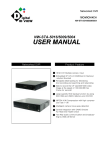
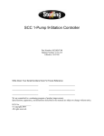
(2) Grounding treatment for the CC-Link cable
(a) Always ground the twisted cable connected to the CC-Link master station, local station and
remote station.
Since the twisted cable is a shielded cable, remove part of the outer sheath. Then ground
the exposed part of the shield indicated in the figure below as wide a surface area as
possible.
Control panel
CC-Link cable
Shield
Remote station
Local station
All of this area should be grounded.
Always use the cable specified for
this cable.
Remote station
Control panel
Also, ground within 30 cm (11.81.in.) from the board terminal area in addition to grounding at
the position closest to the exit of the control panel.
(b) Always use the specified cable for the CC-Link cable.
(c)
For each module, do not use a ferrite core for the CC-Link cable from the board.
(d) For each module, ground both the FG terminal and SLD terminal of the board.
Shielded, twisted cable
Terminal
resistor
Master module
Remote module
Local module
DA
DA
DA
DB
DB
DB
DG
DG
DG
SLD
SLD
SLD
FG
2-4
24V
24V
24G
24G
FG
FG
Terminal
resistor
2. EMC COMMAND
2.1.4
MELSEC
Noise filter (power supply line filter)
A noise filter is a part that has a considerable effect in preventing conductive noise. Except for a few
models, installation of a noise filter to the power supply line is not mandatory. However, the
installation of a noise filter can suppress noise at a higher rate (a noise filter is effective for reducing
noise emitted in the range below 10MHz). Use a noise filter equivalent to the models shown below.
Model
FN343-3/01
FN660-6/06
ZHC2203-11
Manufacturer
SCHAFFNER
SCHAFFNER
TDK
Rated current
3A
6A
3A
Rated voltage
250 V
Precautions when installing a noise filter are noted below.
(1) Do not bundle the wiring on the input and output side of the noise filter. If they are bundled, noise
on the output side will be inducted to the wiring on the input side where the noise has been
removed by a filter.
Input side
(power supply side)
Filter
Induction
Output side
(device side)
Input side
(power supply side)
Filter
Induction
Output side
(device side)
(2) Ground the ground terminal for the noise filter to the control panel using as short wiring as
possible (about 10 cm (3.94 in.)).
2-5
2. EMC COMMAND
MELSEC
MEMO
2-6
3. SYSTEM CONFIGURATION
MELSEC
3. SYSTEM CONFIGURATION
The configuration for a system using the I/F board is explained below.
3.1
System Configuration for A80BDE-J61BT13
The following indicates the system configuration when an I/F board is used.
The I/F board can be connected to a maximum of up to 26 modules per 1 master station.
However, the following conditions must be fulfilled.
(1) {(1×
×a)+(2×
×b)+(3×
×c)+(4×
×d)} ≤ 64
a : Number of modules occupied by 1 station
b : Number of modules occupied by 2 stations
c : Number of modules occupied by 3 stations
d : Number of modules occupied by 4 stations
(2) {(16×
×A)+(54×
×B)+(88×
×C)} ≤ 2304
A : Number of remote I/O stations ≤ 64
B : Number of remote device stations ≤ 42
C : The number of local stations, standby master stations and intelligent device stations ≤ 26
An IBM PC/AT Compatible PC equipped
with a PCI bus *1
Either Windows 95, Windows 98,
or Windows NT Workstation 4.0
has been installed
Software package
SW3DNF-CCLINK
Master module
Local board
Model A80BDE-J61BT13
CC-Link interface board
Terminal resistor
(mandatory) *2
Shielded, twisted cable
Terminal resistor
(mandatory) *2
*1 : A multiprocessor PC cannot be used, since the drivers are not compatible.
*2 : The terminal resistor comes with the master module.
3-1
3. SYSTEM CONFIGURATION
3.2
MELSEC
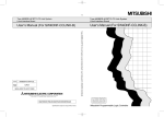
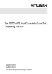
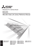
Applicable System
The CC-Link system master module which can use an I/F board is explained below.
The master module that can use an I/F board is the product with function version B or later and
software version N or later.
The product with earlier versions than those listed above cannot use an I/F board.
The function version is recorded in the DATE column of the rated plate.
<Large type>
<Small type>
CPU UNIT
PROGRAMMABLE CONTROLLER
MODEL
DATE
DATE
9712
9712
B
B
MITSUBISHI ELECTRIC CORPORATION JAPAN
BD992D008H40
Year and month
of manufacture
BD992D008H40
MITSUBISHI ELECTRIC
Function
version
Year and month
of manufacture
Function
version
*The function version is noted only on products with version B or later.
The software version is indicated on the module version tag located on the front of the module.
A1SJ61BT11
AJ61BT11
RUN
ERR.
MST
S MST
LOCAL
CPU R/W
E
R
R
O
R
SW
M/S
PRM
TIME
LINE
156K
625K
2.5M
5M
10M
RUN
ERR.
MST
S MST
LOCAL
CPU R/W
L RUN
L ERR.
B
R
A
T
E
STATION NO.
TEST
S0
S1
S2
SW
M/S
PRM
TIME
LINE
E
R
R
O
R
SD
RD
MODE
T
E
S
T
Software version
L RUN
L ERR.
SD
RD
Hardware version
Software version
Hardware version
3-2
3. SYSTEM CONFIGURATION
3.3
MELSEC
Operating Environment
The operating environment for the I/F board is shown below.
Item
Description
PC unit
PC with a Pentium 133 MHz or higher, one or more PCI bus slots, and running Windows 95,
Windows 98, or Windows NT Workstation 4.0
PCI bus specification
5 V DC, 32 bit bus
Basic clock: 33 MHz
Operating system
Either of Windows 95 (English version), Windows 98 (English version), or Windows NT
Workstation 4.0 (English version)
Programming language
Visual Basic Ver5.0 (English version), Visual Basic Ver6.0 (English Version), Visual C++
Ver5.0 (English version), Visual C++ Ver6.0 (English Version)
Required memory size
32 MB or more
Hard disk space
15 MB or more
Disk drive (required when installing the driver)
3.5 inch (1.44 MB) floppy disk drive
Note
A multiprocessor PC cannot be used, since the drivers are not compatible.
3-3
3. SYSTEM CONFIGURATION
MELSEC
MEMO
3-4
4. SPECIFICATION
MELSEC
4. SPECIFICATION
The performance specifications and functions of the I/F board are explained below.
4.1
General Specification
(1) The following table indicates general specifications of the I/F board.
Item
Specification
Usage ambient temperature
0 to 55 °C
Storage ambient
temperature
-20 to 75 °C
Usage ambient humidity
10 to 90 %RH, no condensation
Storage ambient humidity
10 to 90 %RH, no condensation
Frequency
When there is
Conforming intermittent
to JIS B
vibration
3501, IEC
61131-2 When there is
continuous
vibration
Vibration durability
Acceleration
Amplitude
10 to 57 Hz
—
0.075 mm
(0.0030 inch)
57 to 150 Hz
9.8 m/s2
—
10 to 57 Hz
—
0.035 mm
(0.0013 inch)
57 to 150 Hz
4.9 m/s2
—
Sweep count
10 times in each
direction X, Y, Z
(80 minutes)
Conforming to JIS B 3501, IEC61131-2 (147 m/s2, 3 times each in 3 directions)
Shock durability
Usage environment
No corrosive gas
Usage height
Less than 2000 m (less than 6562 ft.)
Installation area
Within the control board
Over-voltage category *1
Less than II
Pollution level *2
Less than 2
*1
*2
Indicates the location where the device is connected from the public cable network to the device
structure wiring area.
Category II applies to the devices to which the power is supplied from a fixed equipment.
Surge withstand voltage for devices with up to 300 V of rated voltage is 2500 V.
This is an index which indicates the degree of conductive object generation in the environment
Pollution level 2 is when only non-conductive pollution occurs.
A temporary conductivity caused by condensation must be expected occasionally.
(2) General specifications of the I/F board after it has been installed conform to the IBM PC/AT
compatible PC unit.
4-1
4. SPECIFICATION
4.2
MELSEC
Performance Specifications
The following table indicates the performance specifications for the I/F board.
Item
Transmission speed
Maximum transmission distance
Specification
156 kbps, 625kbps, 2.5 Mbps, 5 Mbps or 10 Mbps can be selected
Differs depending on the transmission speed. (See Section 4.3)
Number of occupied stations
Maximum number of link points per 1
system
1 or 4 station(s) (switches depending on the setting)
Remote I/O (RX, RY)
Remote registers (RWr) : 256 (local station to master station)
Remote I/O (RX, RY)
Number of link points per 1 station
: 2048
Remote registers (RWw) : 256 (master station to local station)
: 30
Remote registers (RWw) : 4 (master station to local station)
Remote registers (RWr) : 4 (local station to master station)
Communication method
Polling method
Synchronous method
Frame synchronous method
Encoding method
NRZI method
Transmission path
Bus (RS485)
Transmission format
Conforms to HDLC
Error control system
CRC(X16+X12+X5+1)
Cable
Shielded, twisted cable (Section 4.4 Recommended cable)
• Automatic return function
• Slave station separation function
• Error detection using the link special relay and register
RAS functions
• Data link status verification
• OFF-line test (hardware test, line test)
• Abnormal temperature detection
• Watchdog timer error (WDT) detection
Number of boards that can be loaded
Loading slot
Maximum of 4
IBM PC/AT compatible PC
Number of slots occupied
1 slot
Internal voltage consumption (5 V DC)
0.4 A
Weight
0.16 kg (0.35 lb)
4-2
PCI bus slot
4. SPECIFICATION
4.3
MELSEC
Total Extension Distance and Between-Station Distance in the
CC-Link System
The following indicates the total extension distance and between-station distance in the CC-Link
system.
1)
2)
Regardless of the transmission speed setting, the length of the cable must be "2 m (6.56 ft.) or
more" between master stations, local stations, as well as intelligent device stations and each of
their previous and next stations, respectively.
When the transmission speed is 5 Mbps or 10 Mbps, it is necessary to note that the maximum
transmission distance varies depending on the length of the cable between the remote I/O station
and remote device station.
Local station
Standby station
Intelligent device
station
Master
station
Remote I/O station
Remote device station
1)
Remote I/O station
Remote device station
2)
1)
Local station
Standby station
Intelligent device
station
Remote I/O station
Remote device station
1)
Remote I/O station
Remote device station
2)
Maximum transmission distance
(1) When a CC-Link dedicated cable is used (terminal register 110 Ω is used)
Transmission speed
2)
Maximum transmission distance
156 kbps
30 cm (11.81 in.) or more
1200 m (3937.2 ft)
625 kbps
30 cm (11.81 in.) or more
600 m (1968.6 ft)
2.5 Mbps
30 cm (11.81 in.) or more
200 m (656.2 ft)
60 cm (23.62 in.) or more
150 m (492.15 ft)
30 to 59 cm (11.81 to 23.23 in.)
110 m (360.91 ft)
5 Mbps
1)
2 m (6.56 ft) or more
10 Mbps
1 m (3.28 ft) or more
100 m (328.1 ft)
60 to 99 cm (23.23 to 38.98 in.)
80 m (262.48 ft)
30 to 59 cm (11.81 to 23.23 in.)
50 m (164.05 ft)
(2) When a CC-Link dedicated high-quality cable is used (terminal register 130 Ω is used)
Transmission speed
2)
Maximum transmission distance
156 kbps
1)
30 cm (11.81 in.) or more
1200 m (3937.2 ft)
625 kbps
30 cm (11.81 in.) or more
600 m (1968.6 ft)
2.5 Mbps
5 Mbps
30 cm (11.81 in.) or more
200 m (656.2 ft)
60 cm (23.62 in.) or more
150 m (492.15 ft)
30 to 59 cm (11.81 to 23.23 in.)
110 m (360.91 ft)
2 m (6.56 ft) or more
10 Mbps
4-3
1 m (3.28 ft) or more
80 m (262.48 ft)
70 to 99 cm (27.6 to 39 in.)
50 m (164.05 ft)
4. SPECIFICATION
4.4
MELSEC
Twisted Cable Specifications
The following table indicates the specifications for the twisted cable that can be used with the CC-Link
and the recommended cable.
The performance of the CC-Link cannot be guaranteed when cable other than the one recommended
below is used.
Item
Specification
FANC-SB 0.5 mm2 × 3
Model
Cable type
Shielded, twisted cable
Conductor sectional area
0.5 mm2
Conductor resistance (20 °C)
37.8 Ω/km or less
Insulation resistance
10,000 Ω-km or more
Dielectric withstand voltage
500 V DC 1 minute
Electrostatic capacity (1 kHz)
60 nF/km or less
Characteristic impedance (1 MHz)
100 ±15 Ω
DA
Sheath
Shield
blue
Cross-section
white yellow
DB
Aluminum tape
DG
Grounding wire
4.5
Overall dimensions
7 mm (0.28 in.)
Approximate weight
65 kg/km
List of Functions
The following table lists the I/F board functions.
Name
Data communication function
Contents
(1)
Communication for remote input (RX), remote output (RY), remote register (RWw,
RWr) via the CC-Link is possible using the cyclic transmission function.
• Number of link points per station
Remote I/O (RX, RY) : 30
Remote register (RWw) : 4
Remote register (RWr) : 4
(2)
Communication with the master station and intelligent device station is possible
using the transient transmission function.
Test function
Tests can be performed and the hardware checked using the test mode setting.
RAS functions
Automatic return function, slave station separation function, verification of data link
status, off-line test
Self-diagnostic function
• An error message is displayed according to the error code.
• Contents of the fault detected are stored in the special relay or special register.
4-4
5. PROCEDURE AND SETTINGS UP TO THE POINT OF OPERATION
MELSEC
5. PROCEDURE AND SETTINGS UP TO THE
POINT OF OPERATION
This section explains the operating procedure up to the point the I/F board is operated, as well as the
names and setting for each part of the I/F board, wiring method and hardware testing.
5.1
Procedure Up to the Point of Operation
An outline of the procedure up to the point of I/F board operation is explained below.
Start
· · · · · · See Section 5.3, "Name and Setting for Each Part."
Perform I/F board settings.
If the power to the PC is on, turn the power off.
Remove the A80BDE-J61BT13 terminal block.
Install the A80BDE-J61BT13 into the PC.
Fix the A80BDE-J61BT13 with the PC's board fixing screws.
Install the A80BDE-J61BT13 terminal block.
Do the wiring between the I/F board and the master module.
· · · · · · See Section 5.4, "Wiring."
Turn on the power to the PC and install the software package.
· · · · · · See Chapter 6,
"INSTALLING AND UNINSTALLING SOFTWARE PACKAGE."
Test the I/F board.
· · · · · · See Section 7.2.7,
"Operation of the test screen"
Perform data link settings for the I/F board.
· · · · · · See Section 7.2,
"CC-Link Utility Operation"
Startup the CC-Link system.
Execute PC programs.
Complete
Note
Setting on the master module side is mandatory in order to run the CC-Link system. Perform the
settings for the master module side as required.
See the user manual for the master module regarding the master module settings.
5-1
5. PROCEDURE AND SETTINGS UP TO THE POINT OF OPERATION
5.2
MELSEC
Installation
This section gives precautions when handling the I/F board and explains the installation environment.
5.2.1
Precautions when handling
The followings are precautions to be noted when handling the I/F board.
DANGER
CAUTION
• Do not touch the terminal or the connector while the power is turned on.
Doing so may result in electric shock or cause malfunctioning.
• Fasten the I/F board securely using the installation screws and tighten the
installation screws securely within the specified torque range.
If the screws are loose, this may cause malfunctioning.
If the screws are tightened too much, this could cause damage to the screws or
module, leading to malfunctioning.
• Do not directly touch the conductive section of the I/F board.
Doing so could result in malfunctioning or breakdown of the I/F board.
• Tighten the terminal screws within the specified torque range.
If the terminal screws are loose, this may lead to a short or malfunctioning.
If the terminal screws are tightened too much, this could cause damage to the
screws or I/F board, leading to a short or malfunctioning.
• Handle the I/F board in a location where there is no static electricity.
Static electricity could result in failure or malfunctioning.
• Take care that foreign objects such as chips or wiring debris do not get into the PC.
This could result in fire, breakdowns or malfunctioning.
• Do not dismantle or rebuild the I/F board.
This will result in failure, malfunctioning, injury or fire.
• Always turn off all external power before installing or removing the I/F board. If
power is not turned off at all phases, there is a risk of electric shock or damage to
the product.
• When discarding the product, handle it as an industrial waste.
• Do not drop the I/F board or subject it to strong impact.
This will result in failure or malfunctioning of the board.
(1) The tightening torque for the I/F board terminal screws and fixing screws should fall within the
range indicated in the table below.
Screw locations
Tightening torque range
Terminal block terminal screws (M3.5 screw)
59 to 88 N⋅cm
Terminal block installation screws (M3.5 screw)
59 to 88 N⋅cm
(2) See the manual attached to the PC unit for the tightening torque of I/F board installing screws.
5-2
5. PROCEDURE AND SETTINGS UP TO THE POINT OF OPERATION
5.2.2
MELSEC
Installation environment
See the instruction manual accompanying the PC unit regarding installation of the PC unit in which the
I/F board is mounted.
CAUTION
5.2.3
• Always ground the PC unit using grounding type D (Class 3 grounding). Otherwise,
there is the risk of malfunctioning.
If there is an error in operation even when the PC unit is grounded, ground the FG
terminal of the PC unit as well as the SLD terminal of the I/F board.
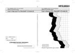
How to remove the terminal block
The I/F board uses a two-piece terminal block, so that the I/F board can be replaced without
disconnecting the signal line to the terminal block.
The illustration below shows how to remove the block.
Screwdriver
HIGH
LOW
Remove the two screws at both ends
of the terminal block and pull them out.
5-3
5. PROCEDURE AND SETTINGS UP TO THE POINT OF OPERATION
5.3
MELSEC
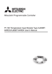
Name and Setting for Each Part
This section explains the name and settings for each part of the I/F board.
4)
RUN ERR
HIGH
1)
LOW
SD
RD
2)
1 2
3)
BD
NO.
Number
Name
1)
Operation display LED
RUN ERR
SD
2)
RD
Terminal block for the
data link
Contents
LED
nomenclature
Contents
ON
RUN
Lights when the I/F board is running
I/F board is normal
properly and turns off when a WDT error
occurs
• WDT error
ERR.
Lights when there is an error in the
network communication status
Data link
communication error
Data link
communication normal
SD
Flashes when the data link is
transmitting data
Flashes while the data link is transmitting
RD
Flashes when the data link is receiving
data
Flashes while the data link is receiving
Connect a twisted cable to perform the data link.
(2-piece terminal block)
Upper surface
of the board
DA
DB
DG
SLD
5-4
OFF
• PC power is OFF
5. PROCEDURE AND SETTINGS UP TO THE POINT OF OPERATION
Name
Number
3)
MELSEC
Contents
Notes
1 2
ON
Channel number setting Sets the channel number for the I/F board.
switch
Board number Channel
Switch
number
1
2
BD
NO.
0
81
OFF
OFF
1
82
ON
OFF
2
83
OFF
ON
3
84
ON
ON
Default setting
Set the board number, so that there is no duplication when two or more I/F boards are installed.
4)
Switch setting pin for
abnormal temperature
detection
Sets the temperature at which to be detected when there is an abnormal temperature.
Setting
Contents
Notes
HIGH
Set the detect temperature at 55 °C.
LOW
Set the detect temperature at 45 °C.
Default setting
HIGH
LOW
5.4
Wiring
5.4.1
Precautions when handling the twisted cable
There is the risk of damage to the twisted cable if it is handled in an extreme fashion. Therefor, do not
handle the cable in the following manner.
(1) Crushing the cable.
(2) Twisting the cable with extreme force.
(3) Pulling the cable with extreme force. (greater than the allowable tension)
(4) Stepping on the cable.
(5) Placing objects on top of the cable.
(6) Damaging the cable cover.
5-5
5. PROCEDURE AND SETTINGS UP TO THE POINT OF OPERATION
5.4.2
MELSEC
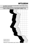
How to wire to each module
The following indicates how to wire the twisted cable for the master module, remote module and I/F
board.
Terminal
resistor
Module other
than QJ61BT11
QJ61BT11
NC
DA
NC
DB
NC
DG
NC
NC
NC
DA
SLD
DB
FG
A80BDE-J61BT13
Remote module
DG
SLD
DA
DB
DG
SLD
DA
DG
+24V
24G
NC
FG
DB
Terminal
resistor
Shielded, twisted cable
SLD
FG
Ground the SLD terminal for
the A80BDE-J61BT13 as required.
[Simplified diagram]
Master module
A80BDE-J61BT13
Remote module
DA
DA
DA
DB
DB
DB
Terminal
resistor
DG
SLD
FG
CAUTION
DG
Shielded,
twisted cable
Terminal
resistor
DG
Shielded,
twisted cable
SLD
Ground the SLD terminal
for the A80BDE-J61BT13
as required.
SLD
FG
• Always ground the PC unit using grounding type D (Class 3 grounding). Otherwise,
there is the risk of malfunctioning.
If there is an error in operation even when the PC unit is grounded, ground the FG
terminal of the PC unit as well as the SLD terminal of the I/F board.
Point
(1) There is a difference in layout between the terminal block for QJ61BT11 and that of other
than QJ61BT11.
(2) Always connect the "terminal resistor" that comes with the master module to the modules at
both ends for the data link. (Connect between DA and DB)
5-6
6. INSTALLING AND UNINSTALLING SOFTWARE PACKAGES
MELSEC
6. INSTALLING AND UNINSTALLING
SOFTWARE PACKAGES
This chapter explains methods on how to install and uninstall software packages to run the board for
each operating system.
6.1
Installing and Uninstalling Software Packages for Windows
95/98/NT 4.0
This section explains methods on how to install and uninstall software packages for Windows
95/98/NT 4.0.
6.1.1
Installing software packages for Windows 95/98/NT 4.0
The following shows the preparation before installation and installation procedure of software
packages for Windows 95/98/NT 4.0.
Point
(1) If operating system is Windows NT 4.0, log on as a user whose privilege is an administrator.
(2) Remove all applications that are included in the Start up menu, then restart Windows before
installing.
(3) The floppy diskettes, 1/5 (first disk) to 5/5 (5th disk) are used for installation.
(4) Uninstall SW0DNF-CCLINK, SW1DNF-CCLINK and SW2DNF-CCLINK before installing
SW3DNF-CCLINK.
Also, the utility setting needs to be configured again as all setting data using each utility is
erased.
(5) SW3DNF-CCLINK performs installation from "Add/Delete Applications" in the "Control
Panel." The other method is to execute "SETUP.EXE". When "SETUP.EXE" is clicked,
installation begins starting from the sixth item.
(1) Preparation before installation (Required only when Windows 95 or 98 is used as OS)
The following explains the preparation procedure to be performed before installing the SW3DNFCCLINK.
1.
2.
Turn on the power to the PC and start Windows.
When the screen shown to the left is displayed, click the
[Next>] button.
↓
(To the next page)
6-1
6. INSTALLING AND UNINSTALLING SOFTWARE PACKAGES
MELSEC
(From the previous page)
↓
3.
When the screen shown to the left is displayed, select
"Search for the best driver for your device.
(Recommended)," and then click the [Next>] button.
4.
When the screen shown to the left is displayed, place a
check in the "Specify a location" check box, then enter
"A:\US" as the search location.
When the setting is completed, insert the floppy disk
marked "5/5" (fifth disk) into the floppy disk drive, and then
click the [Next>] button.
5.
The system searches for a device driver file.
Click the [Next>] button.
6.
The operation is complete when the screen shown to the
left is displayed.
Click the [Finish] button.
↓
↓
6-2
6. INSTALLING AND UNINSTALLING SOFTWARE PACKAGES
MELSEC
(2) Installing SW3DNF-CCLINK
Install SW3DNF-CCLINK according to the following procedure.
1.
2.
Turn on the power to the PC and start Windows.
Open "Start" – "Setting" – "Control Panel".
3.
Open "Add/Remove Programs".
Click [Install · · · ].
4.
When the next screen is displayed, insert the 1/5 (first)
floppy diskette into FDD.
After inserting the floppy diskette, click the [Next>] button.
↓
↓
↓
(To the next page)
6-3
6. INSTALLING AND UNINSTALLING SOFTWARE PACKAGES
MELSEC
(From the previous page)
↓
5.
When the next screen is displayed, it indicates that
"SETUP.EXE" is found. Click the [Finish] button, and start
the installation.
If "SETUP.EXE" was not found, click the [Browse …] button
and change to the directory where "SETUP.EXE" is
located.
6.
After a few moments, the screen similar to what shown left
will be displayed. Select "English (United States)" and click
the [OK] button.
7.
Verify the content, and click the [Next>] button.
8.
Specify the installation destination folder.
The default installation destination folder for SW3DNFCCLINK is "C:\MELSEC".
If the default is fine, click the [Next>] button.
When changing the installation destination folder, click the
[Browse] button and change it.
↓
↓
↓
↓
(To the next page)
6-4
6. INSTALLING AND UNINSTALLING SOFTWARE PACKAGES
MELSEC
(From the previous page)
↓
9.
As the installation starts, follow the instructions and insert
the floppy diskettes in order.
↓
10. When the dialog box shown left is displayed, it indicates
that installation is completed.
To restart, verify that "Yes, I want to restart my computer
now". is checked, then click the [Finish] button.
To restart later, check "No, I will restart my computer later".
and click the [Finish] button.
Point
(1) When the installation fails to complete successfully, and if software packages can be
uninstalled, execute uninstallation.
(2) When performing the re-installation, reinstall after performing the uninstallation.
6.1.2
Icons to be registered
Installing the software packages will register the icons shown below.
The icons shown below are registered in [Start] – [Program] – [MELSEC].
(1)
MELSEC CC-Link Utility
Starts CC-Link Utility.
(2)
Error viewer (for Windows 95/Windows98 only)
Starts Error viewer.
Point
(1) If other I/F board software packages are installed, the icon for the device monitor utilities may
be registered.
(2) If other I/F board software packages are installed, the board diagnosis utilities may be
registered.
A80BDE-J61BT13 cannot use the board diagnosis utilities.
6-5
6. INSTALLING AND UNINSTALLING SOFTWARE PACKAGES
6.1.3
MELSEC
Uninstalling software packages for Windows 95/98/NT 4.0
The following shows uninstallation method for the software packages.
Point
Be sure to execute uninstallation from the control panel.
Do not directly start "UnInstaller.exe" that has been installed.
1.
2.
Select [Start] – [Settings] – [Control Panel] menu.
As control panel is displayed, double-click "Add/Remove
Programs".
3.
Select "SW3DNF-CCLINK", and click the [Add/Remove
(R)] button.
↓
↓
(To the next page)
6-6
6. INSTALLING AND UNINSTALLING SOFTWARE PACKAGES
MELSEC
(From the previous page)
↓
4.
Clicking the [Yes] button starts uninstallation.
5.
If the screen shown left is displayed, click [No to All] button.
Clicking the [Yes] or [Yes to All] button deletes common
files for the MELSEC software packages group, and other
software packages may not start normally.
6.
Upon completing uninstallation, click the [OK] button.
↓
↓
6-7
6. INSTALLING AND UNINSTALLING SOFTWARE PACKAGES
MEMO
6-8
MELSEC
7. UTILITY OPERATION
MELSEC
7. UTILITY OPERATION
Point
If the operating system is Windows NT4.0, use each utility after logging on as the user with an
attribute of administrator.
7.1
Utility Common Operations
This section explains the common operations for each utility.
7.1.1
Starting a utility
An utility can be started by clicking on the following menus found in the [Start] – [Program] –
[MELSEC] menu.
Starts the CC-Link Utility.
Starts the Error Viewer.
*1
*1 : The error viewer is registered only when the operating system
is Windows 95/98.
7.1.2
Starting the device monitor utility
The following explains how to start the device monitor utility from the CC-Link utility.
The device monitor utility can be started by clicking on the [Device Monitor] button found at the bottom
of the CC-Link utility screen.
Click!
7-1
7. UTILITY OPERATION
7.1.3
MELSEC
Ending an utility
This section explains how to end an utility.
(1) To end the utility, click the [Exit] button at the bottom of the utility screen.
Click!
(2) To end the device monitor utility, click [Menu] – [Exit] from the menu bar.
When a dialog box is displayed, clicking the [Yes] button ends the device monitor utility.
Click!
(3) To end the error viewer, click [Log] – [Exit] menu from the menu bar.
Click!
7-2
7. UTILITY OPERATION
7.1.4
MELSEC
Displaying the help screen
This section explains how to display the utility's help screen.
(1) To display the utility's help screen, click the [Help] button at the lower right-hand corner of the
utility screen.
Click!
(2) To display the help screen for the device monitor utility and error viewer, click [Help] – [Help] from
the menu bar.
Click!
7-3
7. UTILITY OPERATION
7.1.5
MELSEC
Verifying the version
This section explains how to verify the utility version.
(1) To verify a utility's version, click the "Version" tab.
Click!
(2) To verify the version for the device monitor utility and error viewer, click [Help] - [Version] from the
menu bar.
Click!
7-4
7. UTILITY OPERATION
7.2
MELSEC
CC-Link Utility Operation
This section explains how to operate the CC-Link utilities.
7.2.1
Operation procedure
The following explains the operation procedure for the CC-Link utilities.
Start
· · · · · · See section 5.1.
Connect a PC to CC-Link.
Perform settings using the CC-Link utilities.
Perform settings using the card
information screen.
· · · · · · See Section 7.2.3.
Confirm the host line status using the line
monitor (host) screen.
· · · · · · See Section 7.2.4.
To check the list of boards, use the card
list screen.
· · · · · · See Section 7.2.2.
To confirm the line status of other
stations, use the line monitor
(other stations) screen.
· · · · · · See Section 7.2.5.
To perform a diagnosis of the memory and
I/O and board reset use, the memory and
I/O diagnostic screen.
· · · · · · See Section 7.2.6.
To perform a network test, use the test
screen.
· · · · · · See Section 7.2.7.
End
7-5
7. UTILITY OPERATION
7.2.2
MELSEC
Card list screen operation
The hardware information that is set for I/F board is displayed.
Item
Description
Channel No.
Displays the channel number.
Board Model Name
Displays the model of CC-Link board that is connected.
IRQ No.
Displays the IRQ number that I/F board uses.
Memory Address
Displays the range of dual-port memory that I/F board occupies.
I/O Port no.
Displays the ranges of I/O port that I/F board occupies.
ROM Ver.
Displays the ROM version of I/F board.
7-6
7. UTILITY OPERATION
7.2.3
MELSEC
Operations on Card Information screen
The card information screen is used to set and to display various information about the installed I/F
board.
Point
When switching screens, set the mode setting to "On-line" or "Off-line."
Item
Channel
Description
Sets a channel to be used.
Sets information on the host.
Item
Board Setting
Setting
Station number
Station 1 to 64
Number of stations occupied
1 station/4 stations
Data entered at fault
Retain/clear
Transmission speed
156 k/625 k/2.5 M/5 M/10 Mbps
7-7
7. UTILITY OPERATION
MELSEC
Item
Description
Display present status of I/F board.
LED name
RUN
CC-Link system normal
ERR.
Communication abnormal
MST
LOCAL
CPU R/W
SW
LED
LED On
Master station
Local station
Communicating
Switch setting error
M/S
Master station duplication error
PRM
Parameter error
TIME
Time over
LINE
Cable disconnection error
L RUN
Data link running
L ERR.
Communication error
156k
625k
2.5M
LED for the set baud rate lights up
5M
10M
TEST
Off-line test executing
SD
Data transmitting
RD
Data receiving
Perform the mode setting for the I/F board, and display the present mode status.
Mode
Mode Setting
"Apply" button
Data
Online (automatic
return yes)
Used for normal communication
Offline
Becomes the state when not connected to the
network.
H/W test mode
Executes a test of the A80BDE-J61BT13
hardware.
[Procedure]
Connect a terminal resistor between the
terminal DA and DB.
Set the mode setting to "H/W test mode" and
press the "Update" button.
The contents of the setting with respect to the I/F board selected by the channel
are updated.
7-8
7. UTILITY OPERATION
7.2.4
MELSEC
Operations on Line Monitor (host) screen
This screen monitors the line status of the host.
Item
Description
Channel
Displays the channel number.
St.
Displays the station number of the host.
Monitors and displays the startup status of the data link.
Status
Contents
Initial status
Data link is in initial status.
No parameter
Parameters have not been received.
Data linking
The data link is being executed.
Data link stopping
The data link has stopped.
Disconnecting (Not poling)
There is no inquiry from the master station and
the link is disconnected.
Disconnecting (Line Error)
The link is disconnected due to an error in the line.
Disconnecting (others)
The link is disconnected due to other reasons.
Data Link Status
Line testing
A line test is being performed.
Parameter Set testing
A test is being performed on the parameter
settings from the master station.
Automatic returning
A return is automatically being processed.
Resetting
The board is being reset.
Monitors and displays the error status.
Display
Normal
Error Status
Link Scan Time
Contents
Normal status
Transmission Error
Error in communication path was detected.
Parameter Error
Error in parameters was detected.
CRC Error
CRC error was detected.
Time Out Error
Timeout error was detected.
Abort Error
An error in the CC-Link board (gate array) was detected.
Setting Error
Error in the setting was detected.
Other Error
Error arising from some other cause was detected.
Max
Displays the maximum value for the link scan time.
(1 ms unit)
Current
Displays the current value for the link scan time.
(1 ms unit)
Min
Displays the minimum value for the link scan time.
(1 ms unit)
7-9
7. UTILITY OPERATION
7.2.5
MELSEC
Operations on Line Monitor (other station) screen
Displays the line status of another station.
Point
The line monitor (other station) only monitors when the host status is "data linking."
Item
Channel
Description
Sets the channel to be used.
Board Setting
Displays information on the host.
St.
Displays the station number that has been set.
Occupy St.
Displays the number of stations occupied.
Displays the type of the station that is set.
Display
Type
Remote Device
Contents
Remote device station
Remote I/O
Remote I/O station
Intelligent
Intelligent station, local station
Displays the status of another station.
Display
Communicating
Status
Other Station
Status
Contents
Normal
Communication interrupted
Communication is stopped
Link error
There is a link error
WDT error
A watchdog timer error occurred
Fuse brake off
A station has blown a fuse
Repeated station
There are duplicate station numbers
Moved switch
Switch was changed
Displays the station with an error invalid.
Invalid
Display
Contents
Error invalid station
There is a setting
(Free)
No setting
Displays the status of a transient error.
Transient Err
Display
Contents
Transient Error
There is an error
(Free)
No error
7-10
7. UTILITY OPERATION
MELSEC
Item
Description
A list of communication status for other stations is displayed.
When a reserve station has been set in the data link parameter that is to set in the
master station, the reserve station is displayed as a normal communication station
in the following list of other station communication statuses.
Other station communication
status list
7.2.6
Operations on Memory I/O Test screen
Diagnoses the dual-port memory and I/O port used by the CC-Link board.
Point
(1) Start the diagnostic operation after disconnecting the external cable.
(2) To switch the screens during the diagnostic operation, click the "Stop" button to terminate the
diagnosis and then switch screens.
Item
Description
Channel
Set the channel to be used.
Diagnose
Displays the address being diagnosed and number of the diagnosis and status.
"Start" button
Starts the memory and I/O diagnosis.
"Stop" button
Terminates the memory and I/O diagnosis.
"Board Reset" button
Resets the CC-Link board.
7-11
7. UTILITY OPERATION
7.2.7
MELSEC
Operation of the test screen
Tests the CC-Link board that is loaded.
Item
Description
Channel
Sets the channel to be used.
Board Setting
Displays information on the host.
Sets the items to be tested.
Test Mode
Item
Network Test
Setting
Performs a test for data link start and stop.
The following dialog box is displayed by clicking.
Select when starting data link.
Select when stopping data link.
"Start" button
Closes the dialog box without performing the test.
Clicking this starts the test.
7-12
7. UTILITY OPERATION
7.3
MELSEC
Device Monitor Utility
This section explains how to operate and set the device monitor utility.
Point
In the device monitor utility, SB (special relay) and SW (special register) are indicated as SM and
SD, respectively.
7.3.1
Operation procedure
The following explains how to operate the device monitor utility.
Start
Select [Setting] - [Network setting] from the menu bar and
set the channel to be used.
· · · · · · See Section 7.3.4
Set the device to be monitored.
· · · · · · See Section 7.3.5.
Change the monitoring method, device value or display
format as necessary.
· · · · · · See Section 7.3.2,
7.3.3, 7.3.6 to 7.3.11
End
7-13
7. UTILITY OPERATION
7.3.2
MELSEC
Setting as batch monitoring
Monitors only one device that has been specified.
(1) Selecting the menu
Select [Menu] – [Batch monitor] from the menu bar.
(Selectable for 16-point register monitor only.)
(2) Display screen
1)
2)
Item
3)
Description
1) Device information
Displays the current device status.
2) Network status
Displays the network status currently set.
3) Data Format
Shows a display form and device types being displayed (word device and bit
device).
See Section 7.3.9 when the display form is changed.
See Section 7.3.4 when the network is set.
See Section 7.3.5 when the device type is changed.
And, see Section 7.3.9 when the display form is changed.
7-14
7. UTILITY OPERATION
7.3.3
MELSEC
Setting as 16 point register monitor
Monitors up to five bit devices and one word device simultaneously.
(1) Selecting the menu
Select [Menu] – [16 point register monitor] from the menu bar.
(Selectable at batch monitoring only.)
(2) Display screen
1)
2)
Item
3)
Description
1) Device information
Displays the current device status.
2) Network status
Displays the network status currently set.
3) Data Format
Shows a display form and device types being displayed (word device and bit
device).
See Section 7.3.9 when changing the display form.
See Section 7.3.4 when setting the network.
See Section 7.3.5 when changing the device type.
And, see Section 7.3.9 when changing the display form.
7-15
7. UTILITY OPERATION
7.3.4
MELSEC
Setting the monitoring destination
Sets the network to be used for device monitoring.
Set this when starting the device monitor utility.
(1) Selecting the menu
Select [Setting] – [Network Setting] from the menu bar.
(2) Dialog box
Item
Description
Channel
Sets the channel to be used.
Network Setting
Sets the host and other stations along with network number and station number.
Logical Sta. No.
Sets the logical station number.
Point
Do not specify a CC-Link remote I/O station or intelligent device station as the monitor
destination.
Specifying a remote I/O station or intelligent device station generates a corresponding error.
7-16
7. UTILITY OPERATION
7.3.5
MELSEC
Setting the device to monitor
Set the device to perform monitoring.
(1) Selecting the menu
Select [Setting] – [Device Setting] from the menu bar.
(2) Dialog box
Batch monitoring
16-points registration monitoring
Item
Description
Sets the device type, block number, and network number to monitor.
And, to monitor the host station device on the CC-Link board, set as follows.
Device Type
Device No.
Register Device List
“Setting” button
“Change” button
“Delete” button
Host station device to monitor
Device type to specify
RX
RY
SB
SW
RWw
Rwr
Random access buffer
Buffer memory
X
Y
SM
SD
Ww
Wr
RAB
SPB
Sets the head number of device to monitor.
(HEX: Hexadecimal, DEC: Decimal, OCT : Octal)
Displays a list of the devices entered .
Enters the data set in device type and device number, and adds them to register
device list.
Selects the device to change, and click this button to change the entered data.
Selects the device to be deleted, and click this button to delete from the register
device list.
Point
The only devices that may be monitored using the 16-point entry monitor are those that have
random access capability. If a device that is not capable of random-access is specified, a device
type error (-3) will occur.
See Chapter 8, "ACEESSIBLE DEVICES AND RANGES," to determine whether or not a device
has random-access capability.
7-17
7. UTILITY OPERATION
7.3.6
MELSEC
Changing word device values
Changes the specified word device data.
(1) Selecting the menu
Select [Device Write] – [Data Changing] from the menu bar.
(2) Dialog box
Item
Description
Device Type
Sets the device type, block number, and network number to change the data.
Device No.
Sets the device number to change the data.
Setting Data
Sets the data to be changed.
(HEX : Hexadecimal, DEC : Decimal, OCT : Octal)
(HEX : Hexadecimal, DEC : Decimal)
DANGER
• Configure the interlock circuit over the sequence program so that the entire system
works safely at all times for data change control to the PLC in operation.
Also, decide on corrective actions for an event of data communication error between
the PC and PLC CPU in use.
7-18
7. UTILITY OPERATION
7.3.7
MELSEC
Changing word device values continuously
Change the specified word device data for the number of specified points being set.
(1) Selecting the menu
Select [Device Write] – [Continuous Change in Data] from the menu bar.
(2) Dialog box
Item
Description
Device Type
Sets the device type, block number, and network number to change the data.
Device No.
Sets the head address to change the data.
(HEX : Hexadecimal, DEC : Decimal, OCT : Octal)
Setting Data
Sets the data to be continuously changed.
Points
Sets the number of points to perform continuos change of the data.
(HEX : Hexadecimal, DEC : Decimal)
(HEX : Hexadecimal, DEC : Decimal, OCT : Octal)
DANGER
• Configure the interlock circuit over the sequence program so that the entire system
works safely at all times for data change control to the PLC in operation.
Also, decide on corrective actions for an event of data communication error between
the PC and PLC CPU in use.
7-19
7. UTILITY OPERATION
7.3.8
MELSEC
Tuning on/off a bit device
Turns on/off the specified bit device.
(1) Selecting the menu
Select [Device Write] – [Bit Device Setting (reset)] from the menu bar.
(2) Dialog box
Item
Description
Device Type
Sets the bit device type, block number, and network number to turn on/off.
Device No.
Sets the bit device number to turn on/off.
(HEX : Hexadecimal, DEC : Decimal, OCT : Octal)
DANGER
7.3.9
• Configure the interlock circuit over the sequence program so that the entire system
works safely at all times for data change control to the PLC in operation.
Also, decide on corrective actions for an event of data communication error between
the PC and PLC CPU in use.
Switching the display form
Switches the display form for device monitor to the selected display form.
The batch monitoring and 16 point entry monitor have different sets of selectable menu.
(1) Selecting the menu
Select [Display switch] – [Word (Bit) Device] from the menu bar.
7-20
7. UTILITY OPERATION
7.3.10
MELSEC
About the Numerical Input pad
By choosing [Option]-[Numerical Pad] on the menu bur, you can use the numerical pad when setting
the device value, etc.
1.
Click the numerical input column.
2.
As the Numerical Pad appears, enter the value with the buttons.
Then, click the “OK” button.
3.
The value is entered.
7-21
7. UTILITY OPERATION
7.3.11
MELSEC
Other operations
Changing data in word device and turning on/off a bit device can be performed by double-clicking the
device number on the screen while monitoring.
(1) Word device
The following shows the operation for changing a word device.
(Only when the display form is 16 bit.)
1.
Double-click the number of the word device to be changed.
2.
As the dialog box shown below is displayed, set any desirable value.
Then, click the [Execute] button.
3.
Select [Yes] in the dialog box shown below if the change is acceptable. Select [No] to cancel it.
DANGER
• Configure the interlock circuit over the sequence program so that the entire system
works safely at all times for data change control to the PLC in operation.
Also, decide on corrective actions for an event of data communication error between
the PC and PLC CPU in use.
7-22
7. UTILITY OPERATION
MELSEC
(2) Bit device
The following shows the operation for turning on/off a bit device.
However, this is operable only when the display form is "Portrait."
1.
Double-click the number of the bit device to be changed.
2.
Select [Yes] in the dialog box shown below, if the change is acceptable.
Select [No] to cancel it.
DANGER
• Configure the interlock circuit over the sequence program so that the entire system
works safely at all times for data change control to the PLC in operation.
Also, decide on corrective actions for an event of data communication error between
the PC and PLC CPU in use.
7-23
7. UTILITY OPERATION
7.4
MELSEC
Error Viewer
This section explains how to operate or set the error viewer.
7.4.1
Screen description
The following explains the error viewer screen.
Item
Type
Description
The error types are displayed by symbols shown below.
Normal message
(Indicates comments that are generated from normal
processing.)
Warning message (Messages that are generated to elicit attention even
though it is not an error.)
Error message
(Displays the error contents that are generated from
each module. For the lines with this symbol, doubleclick to see the detailed message contents, and
remove the cause promptly.)
Date and Time
Displays the date an error occurred.
Time
Displays the time an error occurred.
Source
Displays the source of an error.
Error No.
Displays the number for an error.
Message Contents
Displays the content of an error.
7-24
7. UTILITY OPERATION
7.4.2
MELSEC
Log menu
The following explains the contents of log menu.
Item
Selecting error-entry source
type
Description
Select the error-entry source type to be displayed in the error viewer.
Driver .......................... Displays the messages generated by drivers such as
common memory device.
Basic Middle Ware ..... Displays the messages generated by the common
memory data server and tab control process.
Applied Middle Ware Displays the messages generated by XMOP and OLEX.
Others......................... Displays the messages generated by the application
packages.
Open the Selected File
Open the error log file (*.ELF).
Save with a Name
Save the error log data of the error entry source (driver, etc. ...) currently being
selected to the specified file.
Delete
Erase the error log data of the error entry source (driver, etc. ...) currently being
displayed.
Perform operations according to direction displayed on the dialog box.
Log Setting
Select processing method for which the number of error logs exceeds the number
of maximum entry.
Overwrite in historical order.
Do not register information unless
space is reserved by old information
deletion.
Exit
End the error viewer.
7-25
7. UTILITY OPERATION
7.4.3
MELSEC
View menu
The following explains the contents of display menu.
Item
Description
All Errors
Displays all the errors that occurred per type of error entry source.
Specific Error
Sets the errors displayed on the screen according to the conditions in the dialog
box shown below.
Start display from the first error log.
Start error display from the
specified date.
Display logs up the last error log.
Display errors up to the specified
date.
Display only the errors of a
specified source.
Display only error with the
specified error No.
Search
Search error information of the source name and error code from the error log data
currently being displayed using the dialog box shown below. (pressing the F3 key
will display the same.)
Set a source file name find.
Find the next error information.
Input an error code to find.
7-26
7. UTILITY OPERATION
MELSEC
Item
Detail
Description
Displays detailed information on the error log currently being selected.
(pressing the Enter key after selecting a display item will display the same.)
Displays the details of the error.
No details are given according to the
type of the source.
Displays when the contents of a driver
or buffer memory are referenced.
No data may be displayed according
to the type of the source.
Displays the details of the next error
log information.
Close this dialogue box.
Renew
Display the details of next error log
information.
Updates the data currently being displayed.
7-27
7. UTILITY OPERATION
MELSEC
MEMO
7-28
8. ACCESSIBLE DEVICES AND RANGES
MELSEC
8. ACCESSIBLE DEVICES AND RANGES
This chapter describes the devices and ranges that can be accessed during CC-Link communication.
8.1
Accessible Devices
The following lists the devices that can be accessed during CC-Link communication.
Point
The "Batch" in the following table indicates Batch Read and Batch Write. The "Random" in the
table indicates Random Read, Random Write, Bit Set, or Bit Reset.
8.1.1
Host (personal computer (local station equivalent))
Device
X (RX)
Y (RY)
SB
SW
Ww (RWw)
Wr (RWr)
Accessible/not accessible
Batch
Random
Batch
Random
Batch
Random
Batch
Random
Batch
Random
Batch
Random
Batch
SPB
(Host buffer memory)
Random
MRB
(Host random access buffer)
Random
Batch
8-1
!
!
!
!
!
!
!
!
8. ACCESSIBLE DEVICES AND RANGES
8.1.2
MELSEC
Other station
Access destination
A1N
A0J2H
A1S (-S1)
A1SC24-R2
A1SH
A1SJ (-S3)
A1SJH (-S8)
A2C (J)
A2CC24
(-PRF)
A2S (-S1)
A2SH (-S1)
A2A (-S1)
A2U (-S1)
A2AS
(-S1/S30)
A2USH-S1
Q02 (H) -A
Q06H -A
A3N
A3A
A3U
!
!
!
!
!
!
A4U
Q2A (-S1)
Q3A
Q4A
Q4AR
Q2AS (-S1)
Q2ASH (-S1)
Q02 (H)
Q06H
Q12H
Q25H
Personal
computer
!
!
!
×
!
!
!
!
×
!
!
!
!
!
×
!
!
!
!
!
!
×
!
!
!
!
!
!
×
!
!
!
!
!
!
×
!
!
!
!
!
!
!
!
!
!
!
!
!
!
!
!
!
!
!
!
!
!
!
!
!
!
×
!
!
!
!
!
!
×
!
!
!
!
!
!
×
!
!
!
!
!
!
×
Batch
!
!
!
!
!
Random
×
×
×
×
×
×
×
×
×
! *1
!
!
×
×
×
×
×
×
×
×
×
×
×
×
×
×
×
×
×
Device
Batch
X
Random
Batch
Y
Random
Batch
L
Random
Batch
M
Random
Batch
Special
M (SM), SB
Random
Batch
F
Random
Batch
T (contact)
Random
Batch
T (coil)
Random
Batch
C (contact)
Random
Batch
C (coil)
Random
T (present value)
C (present value)
Batch
Random
Batch
Random
Batch
D
Random
Batch
Special
D (SD), SW
Random
T (set value main)
T (set value sub 1)
T (set value sub 2)
T (set value sub 3)
Batch
Random
Batch
Random
Batch
Random
*1 : A2A(-S1) cannot be accessed.
8-2
!
×
!
×
!
×
!
×
!
×
!
×
×
×
×
×
8. ACCESSIBLE DEVICES AND RANGES
MELSEC
Access destination
A1N
A0J2H
A1S (-S1)
A1SC24-R2
A1SH
A1SJ (-S3)
A1SJH (-S8)
A2C (J)
A2CC24
(-PRF)
A2S (-S1)
A2SH (-S1)
A2A (-S1)
A2U (-S1)
A2AS
(-S1/S30)
A2USH-S1
Q02 (H) -A
Q06H -A
A3N
A3A
A3U
A4U
Batch
!
!
!
!
!
Random
×
×
×
×
×
×
×
! *1
!
!
×
×
×
×
×
×
×
×
×
×
×
!
!
!
!
!
!
!
!
!
×
Q2A (-S1)
Q3A
Q4A
Q4AR
Q2AS (-S1)
Q2ASH (-S1)
Q02 (H)
Q06H
Q12H
Q25H
Personal
computer
×
×
×
×
×
×
×
×
!
×
×
!
!
!
×
!
!
!
×
×
!
!
!
!
!
×
×
!
!
!
!
!
×
!
!
!
!
!
!
×
!
!
!
!
!
!
×
×
×
×
×
×
!
×
×
×
×
×
×
×
×
×
×
×
×
×
×
×
×
!
×
×
×
×
×
×
!
×
×
×
×
×
×
×
×
×
×
×
×
×
!
×
×
×
×
×
×
×
×
×
×
×
×
×
×
×
×
×
×
×
×
×
×
Device
C (set value main)
C (set value sub 1)
C (set value sub 2)
C (set value sub 3)
Batch
Random
Batch
Random
Batch
Random
Batch
A
Random
Batch
Z
Random
V (index register)
Batch
Random
Batch
R (file register)
Random
ER
(extended file resister)
Batch
Random
Batch
B
Random
Batch
W
Random
Batch
Q/QnA link special relay
(within Q/QnA CPU)
Random
Retentive timer
(contact)
Random
Batch
Retentive timer (coil)
Batch
Random
Batch
Q/QnA link special register
(within Q/QnA CPU)
Random
Q/QnA edge relay
(within Q/QnA CPU)
Random
Batch
Batch
Host random-access
buffer
Random
Retentive timer
(present value)
Random
Host link register
(for transmission)
Random
Batch
Batch
Batch
Host link register
(for reception)
Random
Q/QnA SEND function
(Arrival acknowledgment)
Random
Batch
*1 : A2A(-S1) cannot be accessed.
8-3
!
×
!
×
!
×
!
×
×
×
8. ACCESSIBLE DEVICES AND RANGES
MELSEC
Access destination
A1N
A0J2H
A1S (-S1)
A1SC24-R2
A1SH
A1SJ (-S3)
A1SJH (-S8)
A2C (J)
A2CC24
(-PRF)
A2S (-S1)
A2SH (-S1)
A2A (-S1)
A2U (-S1)
A2AS
(-S1/S30)
A2USH-S1
Q02 (H) -A
Q06H -A
A3N
A3A
A3U
×
×
×
×
×
×
A4U
Q2A (-S1)
Q3A
Q4A
Q4AR
Q2AS (-S1)
Q2ASH (-S1)
Q02 (H)
Q06H
Q12H
Q25H
Personal
computer
×
×
×
×
×
×
×
!
×
×
×
×
×
!
×
×
×
×
×
×
!
×
×
×
×
×
×
!
×
×
×
×
×
×
!
×
×
×
×
×
×
!
×
×
×
×
×
×
Device
Q/QnA SEND function
(Arrival acknowledgment)
Batch
Random
Batch
Direct link input
Random
Direct link output
Batch
Random
Batch
Direct link relay
Random
Direct link register
Direct link special relay
(network module side)
Batch
Random
Batch
Random
Batch
Direct link special register
(network module side)
Random
Special direct buffer
register
Random
Other station buffer
memory *1
Batch
!
!
!
!
!
!
Random
×
×
×
×
×
×
×
Batch
!
!
!
!
!
!
!
Other station random
access buffer
Other station RX *1
Other station RY *1
Other station link
register
Other station SB *1
Other station SW *1
Batch
!
×
×
!
Random
×
×
×
×
×
×
×
Batch
!
!
!
!
!
!
!
Random
×
×
×
×
×
×
×
Batch
!
!
!
!
!
!
!
Random
×
×
×
×
×
×
×
Batch
!
!
!
!
!
!
!
Random
×
×
×
×
×
×
×
!
Batch
!
!
!
!
!
!
Random
×
×
×
×
×
×
×
Batch
!
!
!
!
!
!
!
Random
×
×
×
×
×
×
×
*1 : Access to the CC-Link (intelligent device station) module buffer memory installed into each CPU.
8.2
Accessible Range
The range of access during CC-Link communication includes only the module master station, local
station PLC and the intelligent device station for the CC-Link connected by the I/F board, and PC with
I/F board installed.
8-4
9. MELSEC DATA-LINK LIBRARY
MELSEC
9. MELSEC DATA-LINK LIBRARY
This chapter describes the functional overview of the functions included in the library.
9.1
Overview of the MELSEC Data-Link Library
These functions are used when creating a user program that communicates with a PLC CPU. With the
functions, the user can perform communication without being conscious of the hardware type on the
opposite side or the communication protocol.
Personal computer
The user can communicate
with a specified PLC easily
without being conscious of
the communication protocol.
MELSEC data-link library
CC-Link board
CC-Link
CC-Link module
9-1
9. MELSEC DATA-LINK LIBRARY
9.2
MELSEC
Function List
The following table lists the functions comprising the MELSEC data-link library that is provided with the
software package.
Function name
Description
mdOpen
Opens a communication line.
mdClose
Closes a communication line.
mdSend
Performs batch write of devices.
mdReceive
Performs batch read of devices.
mdRandW
Writes devices randomly.
mdRandR
Reads devices randomly.
mdDevSet
Sets a bit device.
mdDevRst
Resets a bit device.
mdTypeRead
Reads the type of PLC CPU.
mdControl
Remote RUN/STOP/PAUSE
mdInit
Refreshes the PLC device address.
mdBdRst
Resets the board itself.
mdBdModSet
Sets the board itself.
mdBdModRead
Reads the board itself.
mdBdLedRead
Reads the LED information of the board itself.
mdBdSwRead
Reads the switch status of the board itself.
mdBdVerRead
Reads the version information of the board itself.
Point
For details of the functions, see HELP on MELSEC communication functions provided in the
software package.
The HELP on MELSEC communication functions can be found in the following directory.
C:\
<MELSEC>
<DrvCommon>
<Help>
9-2
Mdfunc.hlp
9. MELSEC DATA-LINK LIBRARY
9.3
MELSEC
Settings for Using Functions
This section explains the setting procedure in order to use functions.
9.3.1
When using Visual Basic 5.0 and Visual Basic 6.0
The following describes the setting procedure when using Visual Basic 5.0 and Visual Basic 6.0.
1.
Start Visual Basic 5. 0 and Visual Basic 6.0 and select [Project] – [Add standard module]
menu.
2.
Select the "Existing files" tab and select "MDFUNC.BAS."
"MDFUNC.BAS" has been saved in the following directory during installation:
<User-specified folder> – <COMMON> – <INCLUDE>
9.3.2
When using Visual C++ 5.0 and Visual C++ 6.0
The following describes the setting procedure when using Visual C++ 5.0 and Visual Basic 6.0.
(1) When setting an include file
1.
Start Visual C++ 5.0 and Visual C++ 6.0 and select [Tool] – [Option] menu.
2.
Select the "Directory" tab and set the directory type to "Include files."
3.
Double-click the item to set and reference the include file.
"MDFUNC.H" has been saved in the following directory during installation:
<User-specified folder> – <COMMON> – <INCLUDE>
4.
Add "#include<mdfunc.h>" at the beginning of your program.
(2) When setting a library file
1.
Start Visual C++ 5.0 and Visual C++ 6.0 and select [Tool] – [Option] menu.
2.
Select the "Directory" tab and set the directory type to "Library files" in the same
manner as in (1).
3.
Open the workspace to create and select [Project] – [Set].
4.
Select the "Link" tab, set "General" as the category, then type "mdfunc32.lib" in the
object/library module field.
9-3
9. MELSEC DATA-LINK LIBRARY
9.4
MELSEC
Procedure for Programming
The following describes the procedure for programming using the MELSEC data-link library.
In this section, it is assumed that the software package has already been installed.
1) Start the power to the personal computer and start Windows.
Has the utility setting
been performed?
Yes
No
2) Perform utility setting.
See Chapter 7 for the operation.
Yes
Change the setting?
No
3) Perform setting so that the MELSEC data-link library can be used.
· · · · · · See Section 9.3.
4) Create a user application using the MELSEC data-link library.
Open the communication port.
(mdOpen)
Communicate with the PLC CPU and
communication board using various
functions.
No
End program?
Yes
Close the port that was opened by
the mdOpen function. (mdClose)
(To the next page)
9-4
· · · · · · See HELP on MELSEC
communication functions
in the software package.
9. MELSEC DATA-LINK LIBRARY
MELSEC
(From the previous page)
5) Invoke the created user application.
6) Access with the PLC CPU and communication board.
7) End the user application.
Point
Perform the processing for opening and closing a communication line (mdOpen / mdClose) only
once at the beginning and end of a program.
Repeating opening and closing of a communication line for each transaction will degrade the
communication performance.
When accessing the PLC CPU and communication board again with the user created application
program, they can be accessed by performing steps 5) to 7) only.
9.5
Channel
The following is the channel used by the MELSEC data library:
Number
81 to 84
9.6
Channel name
CC-Link (1st board to 4th board)
Description
This is used when communication via the CC-Link board.
This is set using the BD No. DIP switch on the back of the CC-Link board.
The following will be set using the SW1 and SW2 settings.
81: OFF, OFF 82: ON, OFF 83: OFF, ON 84: ON, ON
Station Number Settings
The following lists the station numbers specified via functions.
Communication
CC-Link
Station number specification
Host: 255 (0xFF)
Other station: 0 to 64(0x40) *3
9-5
9. MELSEC DATA-LINK LIBRARY
9.7
MELSEC
Device Types
Either code number or device name can be specified for functions as the device type.
(1) Only when via I/F board
The following table shows the CC-Link dedicated device type when accessing to the device via
I/F board.
Device type
Device
Code specification
Device name specification
Decimal
Hexadecimal
1
1H
Dev X
2
2H
Dev Y
Host RY
5
5H
Dev SM
Host SB (link special B for CC-Link)
Host SW (link special W for CC-Link)
Host RX
14
EH
Dev SD
33
21H
Dev MRB
Host random access buffer
36
24H
Dev Ww
Host link register (for transmitting)
37
25H
Dev Wr
Host link register (for receiving)
50
32H
Dev SPB
Host buffer memory
32768
8000H
Dev RBM
Other buffer memory *1
32800
8020H
Dev RAB
Other random access buffer *1
32801
8021H
Dev RX
Other RX *1
32802
8022H
Dev RY
Other RY *1
32804
8024H
Dev RW
Other link register *1
32867
8063H
Dev SB
Other SB (link special; B for CC-Link) *1
32868
8064H
Dev SW
Other SW (link special; W for CC-Link) *1
*1 : Cannot use with mdRandR, mdRandW, mdDevSet and mdDevRst functions.
9-6
9. MELSEC DATA-LINK LIBRARY
MELSEC
(2) Common
The following table shows the common device type for all communication course.
Device type
Device
Code specification
Device name specification
Decimal
Hexadecimal
1
1H
DevX
X
2
2H
DevY
Y
3
3H
DevL
L
4
4H
DevM
M
5
5H
DevSM
Special M (SM), SB (link special B for MNET/10)
6
6H
DevF
F
7
7H
DevTT
T (contact)
8
8H
DevTC
T (coil)
9
9H
DevCT
C (contact)
10
AH
DevCC
C (coil)
11
BH
DevTN
T (present value)
12
CH
DevCN
C (present value)
13
DH
DevD
D
14
EH
DevSD
Special D (SD), SW (link special W for MNET/10)
15
FH
DevTM
T (set value main)
16
10 H
DevTS
T (set value sub 1)
16002
3E82 H
DevTS2
T (set value sub 2)
16003
3E83 H
DevTS3
T (set value sub 3)
17
11 H
DevCM
C (set value main)
18
12 H
DevTS
C (set value sub 1)
18002
4652 H
DevTS2
C (set value sub 2)
18003
4653 H
DevTS3
C (set value sub 3)
19
13 H
DevA
A
20
14 H
DevZ
Z
21
15 H
DevV
V (index register)
22
16 H
DevR
R (file register)
22001 to 22256
55F1H to 56F0 H
DevER to DevER256
ER (extension file register)
23
17 H
DevB
B
24
18 H
DevW
W
25
19 H
DevQSB
Q/QnA link special relay (within the Q/QnA CPU)
26
1A H
DevSTT
Retentive timer (contact)
27
1B H
DevSTC
Retentive timer (coil)
28
1C H
DevQSW
Q/QnA link special register (within the Q/QnA CPU)
30
1E H
DevQV
Q/QnA edge relay (within the Q/QnA CPU)
9-7
9. MELSEC DATA-LINK LIBRARY
MELSEC
Device type
Device
Code specification
Device name specification
Decimal
Hexadecimal
33
21H
DevMRB
35
23H
DevSTN
Retentive timer (present value)
36
24H
DevWw
Host link register (for transmitting) *1
37
25H
DevWr
Host link register (for receiving) *1
40
28H
DevFS
FXCPU S-device
50
32H
DevSPB
Host buffer memory *1
101
65H
DevMAIL
Q/QnA SEND/RECV function (Arrival acknowledgment)
102
66H
DevMAILNC
Q/ QnA SEND/RECV function (No arrival acknowledgment)
Host random access buffer *1
1001 to 1255
3E9H to 4E7H
DevLX1 to DevLX255
Direct link input
2001 to 2255
7D1H to 8CFH
DevLY1 to DevLY255
Direct link output
23001 to 23255
59D9H to 5AD7H
DevLB1 to DevLB255
Direct link relay
24001 to 24255
5DC1H to 5EBFH
DevLW1 to DevLW255
Direct link register
25001 to 25255
61A9H to 62A7H
DevLSB1 to DevLSB255
Direct link special relay (network module side)
28001 to 28255
6D61H to 6E5FH
DevLSW1 to DevLSW255
Direct link special register (network module side)
29000 to 29255
7148H to 7247H
DevSPGO to DevSPG255
Special direct buffer register
31000 to 31255
7918H to 7A17H
DevEMO to DevEM255
EM (shared device)
32000 to 32255
7D00H to 7DFFH
DevEDO to DevED255
ED (shared device)
*1 : Dedicated device for accessing the buffer memory for the I/F board (host).
9-8
10. ERROR CODE
MELSEC
10. ERROR CODE
An error code is returned as the return value when a function is executed.
The error definition and corrective action that correspond to each error code are described.
Return value
(HEX)
Error definition
Corrective action
0
Normal completion
1
Driver not started
The driver has not been started.
The interrupt number/I/O address are overlapping with other board.
Correct the error occurred during driver startup.
Check the board setting.
2
Board response error
Time out has occurred while waiting for a response to the corrective
action.
Check the operation status of the access
station(s) and loading condition of the board(s).
Retry in an application program.
65
(41)
Channel error
An unregistered channel number was specified.
Check the channel number.
66
(42)
OPEN error
The specified channel has already been opened.
Open only once.
67
(43)
CLOSE error
The specified channel has already been closed.
Close only once.
68
(44)
PATH error
A path other than the opened line was set.
Specify the station with an open path.
69
(45)
Processing code error
An unsupported processing code was issued.
Use the supported processing code.
70
(46)
Station specification error
The specified station is incorrect.
A process that should have been requested to other station was
requested to the host. Or, the station number corresponds to the host
(0xFF) but the network number is not 0.
Correct the specification of the station number in
the application program.
71
(47)
Reception data error (during RECV request)
Data has not been received.
Wait until data is received.
72
(48)
Waiting for mode setting
Mode setting has not been performed.
Perform mode setting.
Mode error
Processing was requested to other station when the mode setting was not Set the mode to online. Or, cancel the request.
online.
73
(49)
Interrupt number error
The interrupt number is overlapping with other board.
I/O address error
The I/O address is overlapping with other board.
Check the board setting.
77
(4D)
Memory error
Enough memory could not be secured.
Terminate other application(s) currently running.
Check if the system is operating normally.
Reboot the system.
78
(4E)
Time out error during mode setting
Mode setting was attempted but failed due to time out.
Restart after checking that the dual-port memory
is not overlapping with other board.
Hardware fault.
79
(4F)
S/W setting data error
Incorrect data was found in the argument parameter when setting S/W.
Check the argument parameter of S/W setting
data.
80
(50)
Unsuccessful mapping of common memory address.
Check if the common address is overlapping
with other I/F board.
81
(51)
Channel response error at source (When a SEND request is issued)
Received an abnormal response to the SEND request.
Retry.
Check if the system is operating normally.
Reboot the system.
85
(55)
Channel number error (during RECV request)
A channel number error.
Check the channel number used during the
RECV request.
100
(64)
Accessing host board
An access request was issued to the host board while the host board is
being accessed.
Retry.
101
(65)
Routing parameter error
The routing parameter is not set.
Correct the routing parameter.
102
(66)
Data transmission error
Data transmission has failed.
Retry.
Check if the system is operating normally.
Reboot the system.
10-1
10. ERROR CODE
Return value
(HEX)
MELSEC
Error definition
Corrective action
103
(67)
Data receiving error
Data receiving has failed.
Retry.
Check if the system is operating normally.
Reboot the system.
129
(81)
Device type error
The specified device type is invalid.
Check the device type.
130
(82)
Device number error
The specified device number is out of range.
When specifying the bit device, the device number is not a multiple of 8.
Check the device number.
131
(83)
Device points error
The specified number of points is out of device range.
When specifying the bit device, the device number is not a multiple of 8.
Check the size.
132
(84)
Number of bytes written error
The specified number of bytes written is out of range.
Set a number of bytes written that is within the
range.
133
(85)
Link parameter error
The link parameter is corrupt.
The total number of slave station is 0.
Reset the link parameter.
136
(88)
Random write specification error
A value other than 0 through 2 was specified for random write.
Set a new value between 0 and 2.
Reception data length error
The length of reception data or byte length is out of range.
Retry.
Check the cable.
Request data buffer length over
The length of request data is out of request data area.
Reduce the request data size.
216
(D8)
Protocol error
The communication procedure is abnormal.
The requested code does not exist.
Check the cable.
217
(D9)
Address error
The address is out of access range.
Check the request data.
219
(DB)
Write error
Unable to write.
Check the request data.
224
(E0)
PC number error
The destination station does not exist.
Correct the station number.
225
(E1)
Processing mode error
A processing code that cannot be processed by the destination ACPU
was set.
(It is checked by the destination ACPU.)
Check the destination ACPU and processing
code.
226
(E2)
Special module specification error
The specified special module is not a module that can be processed.
Correct the Y number.
227
(E3)
Other data error
Incorrect data was found in the address, head step or shift value of the
request data.
Correct the request data.
228
(E4)
Link specification error
A processing code that cannot be processed by the destination station
was set.
(It is checked by the destination link module.)
Check the destination station number and
processing code.
232
(E8)
Remote error
The keyword did not match for the remote RUN/STOP/PAUSE request.
Check the destination station number and processing code.
Check the destination station number and
processing code.
233
(E9)
Link time over
The destination disconnected the link while processing.
Check the hardware of the special module.
234
(EA)
Special module BUSY
Either the receive buffer is full at the destination due to transmission of
general data, or preparation for receiving data has not been completed.
Check the hardware of the special module.
236
(EC)
Destination BUSY
Either the receive buffer is full at the destination due to transmission of
general data, or preparation for receiving data has not been completed.
Execute the request when the destination can
receive data.
240
(F0)
Link error
A request was issued to a disconnected link station.
Return the link.
241
(F1)
Special module bus error
Processing preparation has not been completed for the specified special
module.
Check the hardware of the special module.
215
(D7)
10-2
10. ERROR CODE
Return value
(HEX)
MELSEC
Error definition
Corrective action
Special module time over
No response from the specified special module.
Check the hardware of the special module.
No response from the MELSECNET (II) board.
Check the hardware of the MELSECNET (II)
board.
1280
(500)
Host board memory access error
Check the switch setting on the host board and
move the memory address to the area that is not
effected by other board.
Change the memory access setting to 16 bit if it
is set to 8 bit.
1281
(501)
Unable to access I/O port
Check the I/O port address setting.
Perform a board self-loopback test and check
the hardware.
16386
(4002)
A request that cannot be processed was received.
Change the request destination.
16432
(4030)
The specified device type does not exist.
Check the specified device type.
16433
(4031)
The specified device number is out of range
Check the specified device number.
16448
(4040)
The module does not exist.
Do not issue a request that generated an error to
the specified special module.
16449
(4041)
The number of device points is out of range.
Check the head address and number of access
points and access within the existing range.
16450
(4041)
Corresponding module error
Check if the specified module is operating
normally
16451
(4043)
The module does not exist at the specified location.
Check the head I/O number of the specified
module.
40577
(9E81)
Device type error
The device type specified for the destination station is invalid.
(It is checked by the destination link module).
Check the device type.
40578
(9E82)
Device number error
The device number specified for the destination station is out of range.
When specifying the bit device, the device number is not a multiple of 8.
(It is checked by the destination link module).
Check the device number.
40579
(9E83)
Devices points error
The number of points specified for the destination station is out of range.
When specifying the bit device, the device number is not a multiple of 8.
(It is checked by the destination link module).
Check the size.
-1
(FFFF)
Path error
The specified path is invalid.
Check the bus that was returned by the mdOpen
function.
-2
(FFFE)
Device number error
The specified device number is out of range.
When specifying the bit device, the device number is not a multiple of 8.
Check the head device number for the specified
device.
-3
(FFFD)
Device type error
The specified device type is invalid.
Check if the device type used is in the device
list.
-4
(FFFC)
CPU error
An invalid station was specified.
Check the status of the communication station.
Check the specified station number.
-5
(FFFB)
Size error
The device number and size are over the device range.
Access was attempted using an odd device.
The device number and size are over the range for the same block.
Check the specified device size.
Check the device number and size.
-6
(FFFA)
Number of block error
The number of blocks specified in dev[0] for device random read/write is
out of range.
Check the number of blocks specified in dev [0].
-8
(FFF8)
Channel number error
The channel number specified in the mdOpen function is invalid.
Check the specified channel number.
242
(F2)
10-3
10. ERROR CODE
Return value
(HEX)
MELSEC
Error definition
Corrective action
-11
(FFF5)
Insufficient buffer area
The read area size of the read data storage array variable is too small.
Check the read size and read data destination
size.
-12
(FFF4)
Block error
The specified block number of the extension file register is invalid.
Check the block number (device type) of the
extension file register.
-13
(FFF3)
Write protect error
The specified block number of the extension file register is overlapping
with the write protect area of the memory cassette.
Check the block number (device type) of the
extension file register.
Check the write protect DIP switch of the
accessed memory cassette.
-14
(FFF2)
Memory cassette error
No memory cassette is loaded to the accessed CPU, or an incorrect
memory cassette is loaded.
Check the accessed memory cassette.
-15
(FFF1)
Read area length error
The read area size of the read data storage array variable is too small.
Check the read size and read data destination
size.
-16
(FFF0)
Station number/network number error
The station number/network number is out of range.
Check the specified station number/network
number
-17
(FFEF)
All-station/group number specification error
A function that does not support all-station specification/group-number
specification was specified.
Check if all-station specification/group number
specification is enabled for the function.
-18
(FFEE)
Remote instruction error
A code that is not designated was specified.
Check the specified code.
-19
(FFED)
SEND/RECV channel number error
The channel number specified with the SEND/RECV function is out of
range.
Check the specified channel number.
-21
(FFEB)
Error in gethostbyname (•)
An error occurred in the function, gethostbyname (•).
Check if the specified host name exists in the
HOSTS file.
-24
(FFE8)
Time out error in select (•)
A time out error occurred in the function, select (•).
Check if MGW server service has been started
on the server machine.
-25
(FFE7)
Error in sendto (•)
An error occurred in the function, sendto (•).
-26
(FFE6)
Error in recvfrom (•)
An error occurred in the function, recvfrom (•).
-28
(FFE4)
Error response reception
An error response was received.
-29
(FFE3)
Reception data length over
Too much data was received.
-30
(FFE2)
Sequence number error
The received sequence number is abnormal.
-31
(FFE1)
DLL load error
An attempt to load a DLL, which is necessary to execute the function, has
failed.
Setup the package again.
-32
(FFE0)
Other task/thread is occupying the resource and the resource is not
released within 30 seconds.
Retry.
There may be a problem of insufficient memory.
Terminate other application(s) currently running.
Check if the system is operating normally.
Reboot the system.
-33
(FFDF)
Incorrect access destination
The setting for the communication destination is incorrect.
-34
(FFDE)
Registry error
An attempt to open the registry has failed.
Check if normal Ethernet communication can be
performed with the server machine.
10-4
Check if the communication destination is
correctly set by the utility.
10. ERROR CODE
Return value
(HEX)
MELSEC
Error definition
-35
(FFDD)
Registry read error
An attempt to read from the registry has failed.
-36
(FFDC)
Registry write error
An attempt to write to the registry has failed.
-37
(FFDB)
-38
(FFDA)
-39
(FFD9)
Corrective action
Check if the communication destination is
correctly set by the utility.
Communication initialization setting error
An attempt to perform initial setting for communication has failed.
Ethernet communication error
An attempt to set for Ethernet communication has failed.
COM communication setting error
An attempt to set for COM communication has failed.
Retry.
There may be a problem of insufficient memory.
Terminate other application(s) currently running.
Check if the system is operating normally.
Reboot the system.
Retry.
Check if the communication destination is
correctly set by the utility.
There may be a problem of insufficient memory.
Terminate other application(s) currently running.
Check if the system is operating normally.
Reboot the system.
-41
(FFD7)
COM control error
Control cannot be performed properly during COM communication.
-42
(FFD6)
Close error
Communication cannot be closed.
-43
(FFD5)
ROM operation error
A TC setting value was written to the CPU during ROM operation.
Change the TC setting value during RAM
operation.
-44
(FFD4)
LLT communication setting error
An attempt to set for LLT communication has failed.
Retry.
Check if the communication destination is
correctly set by the utility.
There may be a problem of insufficient memory.
Terminate other application(s) currently running.
-45
(FFD3)
Ethernet control error
Control cannot be performed properly during Ethernet communication.
Retry.
Check if the system is operating normally.
-46
(FFD2)
USB open error
Failed to initialize and open the USB port.
There may be a problem of insufficient memory.
Terminate other application (s) currently running.
Check if the system is operating normally.
Reboot the system.
-47
(FFD1)
Random read condition disable error
The random read condition is not enabled and random read cannot be
performed.
A conditional random read has been set via a
switch such as GPPW. Wait until the condition is
enabled. Alternatively, cancel the condition.
-50
(FFCE)
Opened path maximum value over
The number of open paths exceeds the maximum value (32).
Close several paths.
-51
(FFCD)
Exclusive control error
An error occurred in the exclusive control.
Retry.
Check if the system is operating normally.
-2174
(F782)
Destination station number specification error
The destination station number for the processing request is specifying
the host.
Check the destination station number.
-16386 to
-20222
(B102 to
BFFE)
See AJ61QBT11/A1SJ61QBT11 CC-Link system master local module
user's manual.
Same as left.
-18560
(B780)
Transient was issued to the remove I/O.
Check the destination station to request.
-18575
(B771)
A device for other station only was accessed to the host.
Check the device type.
-24957
(9E83)
Device points error
The number of points specified for the destination station is out of device
range.
When specifying the bit device, the device number is not a multiple of 8.
(It is checked by the destination link module.)
Check the size.
-24958
(9E82)
Device number error
The device number specified for the destination station is out of range.
When specifying the bit device, the device number is not a multiple of 8.
(It is checked by the destination link module.)
Check the device number.
-24959
(9E81)
Device type error
The device type specified for the destination station is invalid.
(It is checked by the destination link module.)
Check the device type.
10-5
Retry.
Check if the system is operating normally.
Reboot the system.
10. ERROR CODE
Return value
(HEX)
MELSEC
Error definition
Corrective action
-25056
(9E29)
Processing code error
A processing code that cannot be processed by the destination station
was set.
(It is checked by the destination link module.)
Check the destination station number and
processing code.
-26333
(9923)
The ROM version of the I/F board does not match the QCPU (Q mode).
Access a CPU other than the QCPU (Q mode).
Use the I/F board supplied with the module
(ROM version: "W" or later) after the SW3DNFCCLINK.
-26334
(9922)
Board reset error
Other process has executed a board reset using the same channel while
other station is being accessed.
Retry.
-26336
(9920)
Request error for other loop
Routing to other loop was performed.
Change the routing destination to AnUCPU or
QnACPU.
-28150
(920A)
Data link disconnecting error
A host link device was accessed while the data
link is being disconnected.
-28151
(9209)
APS No. error.
An incorrect response data was received.
Change the equipment at the process request
destination.
-28156
(9204)
Dual-port hand-shake error
Remove other optional board.
-28158
(9202)
WDT error
Reset the board.
Reboot the PC.
10-6
11. TROUBLESHOOTING
MELSEC
11. TROUBLESHOOTING
This chapter describes how to determine the cause of trouble that may occur during system
construction as well as appropriate corrective actions.
11.1
When Performing Troubleshooting
Ideally occurrence of trouble should be kept to a minimum in order to startup the system effectively.
However, once an error occurs, it is important that we identify the cause as quickly as possible.
The followings are the three basic points that must be kept in mind when performing troubleshooting.
(1) Visual check
Check the following points.
1) Movement of the external device (status when stopped or during operation)
2) On/off status of power supply
3) Wiring condition (cable)
4) LED display status (power supply display LED)
5) Checks whether the PC is one suitable for the operating environment
After checking 1) through 5), connect the external device and check the operation of the user
program.
(2) Confirming the error
Examine how the error status changes by the following operation.
1) Change the input status and check if the change can be read correctly using the test
program.
2) Repeat on/off of output and check if the status of the external device changes accordingly.
(3) Narrowing the range
Based on the steps 1) and 2) above, deduce the range of error location as one of the following.
1) PC side or external device side
2) PC main body or board
3) Cable
4) User program
11-1
11. TROUBLESHOOTING
11.2
MELSEC
Troubleshooting Table by the Type of Error Occurring
When trouble occurs, refer to the methods in Table 11.1 for determining the cause of the trouble.
Table 11.1 Troubleshooting table by the type of error occurring
No.
[Error content]
[Cause determination method]
1
An I/F board did not operate normally upon startup.
See the flowchart found in
Section 11.3 for when the board
and PC do not operate.
2
There was no data linking although the master station and other station were
connected to the I/F board.
See the flowchart found in
Section 11.4 for when the data
link could be completed.
When an error occurs during the data link
1) An unexpected value is entered in the special device.
3
2) The device is being accessed using a function in the user program, but
data cannot be read or written.
3) Communication stops occasionally while the user program is executing.
4) The system goes down (blue screen) or resets while the user program is
executing in Windows NT 4.0 or Windows 95/98.
11-2
See the flowchart found in
Section 11.5 for when an error
occurs during data linking.
11. TROUBLESHOOTING
11.3
MELSEC
Flowchart to Use when the Board or PC do not Operate
The following indicates a check procedure in the PC unit when the I/F board does not run normally
during startup.
START
Is the A80BDE-J61BT13
"RUN" LED lit?
NO
YES
Is the operating system
starting normally?
NO
Remove any other optional
boards and leave only the
A80BDE-J61BT13 in.
YES
Is there
a driver message in the
management tool event
viewer? *1
NO
2)
Replace the A80BDE-J61BT13.
YES
Is a WDT error occurring?
NO
Replace the A80BDE-J61BT13.
YES
Start the utility.
With the board information screen,
press the update button and reset
the board.
Is a WDT error occurring?
YES
Replace the A80BDE-J61BT13.
NO
END
When the
operating system was
started, did the screen change
to blue, then displayed
a system error?
YES
Remove all A80BDE-J61BT13.
NO
When the
operating system was
started, did the screen change
to blue, then displayed
a system error?
YES
NO
Replace the A80BDE-J61BT13.
1)
11-3
Reinstall Windows NT4.0 or
Windows 95/98, or contact the
Microsoft Corp.
11. TROUBLESHOOTING
MELSEC
2)
1)
Is there a driver
message in the control tool
event viewer? *1
YES
NO
Start the monitor function (utility).
Did the monitor
function (utility) start
normally?
Check switching settings, etc.
according to the error contents in
the event viewer.
NO
Remove any other optional
boards and leave only the
A80BDE-J61BT13 in.
YES
Did the monitor function
(utility) start normally?
Are the
correct numbers
of A80BDE-J61BT13 that
have been loaded
displayed?
NO
YES
Check the I/O, IRQ and memory
address settings for other optional
boards.
NO
YES
END
Replace the A80BDE-J61BT13.
NO
Is everything OK?
YES
Replace the PC.
*1 : With Windows 95 or 98, check the driver message in the error viewer.
11-4
END
11. TROUBLESHOOTING
11.3.1
MELSEC
Table of error event messages that may occur during driver startup
The table below lists the errors displayed in the event viewer/error viewer.
Event ID
(HEX)
Error content
Corrective action
256
(100)
The driver could not be executed because an error
occurred during driver startup.
Reinstall the driver package. If the error
occurs again, reinstall Windows NT 4.0 or
Windows 95/98.
257
(101)
The I/F board could not be detected.
Check the installation status of the I/F
board.
258
(102)
No response from hardware.
Replace the I/F board.
259
(103)
The number of boards detected exceeds the maximum
number that can be loaded.
Remove boards until the number falls within
the maximum limit.
262
(106)
An attempt to link the device name has failed.
Reinstall Windows NT 4.0 or Windows
95/98.
268
(10C)
An error occurred during receiving process.
(The request packet is incorrect).
269
(10D)
An error occurred during transmission process.
Check the PC and PLC program for which
the processing is being requested to this
PC.
279
(117)
An error occurred when writing to the registry.
Reinstall the software package.
280
(118)
A request that cannot be processed was received from
other station.
(A request for which a response request cannot be
processed was received )
Check the PC and PLC program for which
the processing is being requested to this
PC.
282
(11A)
Mapping of the I/O port has failed.
The I/O port is overlapping with another
resource. Remove other optional boards.
283
(11B)
The shared memory area of the I/F board is
overlapping with other hardware.
Remove other optional boards.
284
(11C)
The I/F board IRQ is overlapping with other hardware.
Remove other optional boards.
285
(11D)
It is possible the I/F board will not operate normally,
since it detected a temperature abnormality.
Install the PC in a location with a suitable
temperature.
286
(11E)
Failed to secure the memory area required to start the
driver.
Increase system memory.
288
(120)
A WDT error occurred.
Remove other optional boards.
289
(121)
Handshaking with the shared memory area has failed.
Reset the board. If the error occurs again,
replace the board.
290
(122)
The board number of the I/F board is a duplicate.
Reset so there are no duplicate board
numbers.
291
(123)
Failed in mapping the shared memory area.
Remove other optional boards.
293
(125)
Interrupt registration has failed.
Remove other optional boards.
294
(126)
The I/O port for the I/F board is overlapping with other
hardware.
Remove other optional boards. *1
11-5
11. TROUBLESHOOTING
MELSEC
Event ID
(HEX)
Error content
DUMP
value
1281
(501)
Initialization
of the I/F
board has
failed.
Corrective action
Error contents (details)
————————
01h
There is no response from the
hardware.
Replace the I/F board.
02h
The IRQ or memory is
overlapping. *2
Remove other optional boards.
03h
There is no response from the
hardware.
Replace the I/F board.
04h
Handshaking with the shared
memory area has failed.
Restart. If the error occurs again, replace
the board.
66h
There is no response from the
hardware.
Replace the I/F board.
DUMP value ............. Value of the 1 byte at the head of the data contents details area
*1 : If this event error occurs in the Windows NT 4.0 event viewer, restart the PC that has the BIOS
setup shown below after setting the "Plug & Play O/S" in [No] and "Reset Configuration Data" in
[Yes] as in the following example.
Example )
BIOS Setup Utility
Set
Plug & Play O/S : [YES]
Reset Configuration Data: [No]
→ [No]
→ [YES]
Then restart.
*2 : This event error may occur when the PCI bus controller is not operating correctly.
When the PC being used comes pre-installed with Windows 95/98, use the drivers for Windows
95/98 and the PCI bus controller that come in the PC unit.
If Windows 95/98 have been purchased separately, obtain the drivers for the PCI bus controller
suggested by the PC manufacturer and install.
11-6
11. TROUBLESHOOTING
11.4
MELSEC
Flowchart to Use when the Data Link could not be Completed
The following flowchart indicates when the data link could not be completed even though the I/F board
was connected to another station.
START
Check the A80BDE-J61BT13 LED.
Is the "RUN" LED unlit?
YES
See Section 11.4.1,
"Flowchart to use when RUN LED
is unlit."
NO
Is the "SD/RD" LED lit?
YES
See Section 11.4.2,
"Flowchart to use when the SD/RD LED
does not light."
NO
Start the monitor function (utility) and
select line monitor from the menu.
Is an error occurring?
NO
Complete
YES
See Section 11.4.3.
"Flowchart to use when there is a
communication error in the master
station and I/F boards."
11-7
11. TROUBLESHOOTING
11.4.1
MELSEC
Flowchart to use when RUN LED is unlit
START
Is it unlit during
communication with
other stations?
YES
Is communication with
other station continued?
NO (The "RUN" LED has been off since the power was turned on.)
Replace the A80BDE-J61BT13.
NO (The "RUN" LED turned
off while communicating)
YES
Replace the A80BDE-J61BT13.
Is the "RUN"
LED still unlit even after the
A80BDE-J61BT13 was
replaced?
NO
YES
Adjust PC hardware, etc.
11-8
Complete
11. TROUBLESHOOTING
11.4.2
MELSEC
Flowchart to use when SD/RD LED does not turn on
An error occurs.
Are the
parameters for the
master station
OK?
NO
Check the parameters for
the master station.
NO
Does the
"RD" LED remain
unlit?
YES
YES
Does the
"SD" LED remain
unlit?
NO
YES
Using the PC, turn the
RX, RY, RWw and RWr
assigned to the host
on/off.
Using the other station,
turn the RX, RY, RWw
and RWr being used in
the PC on/off.
Monitor the RX, RY,
RWw and RWr with the
other station.
Monitor the RX, RY, RWw
and RWr with the PC.
Did the RX,
RY, RWw and RWr
turn on/off with
the PC?
NO
NO
Replace the
A80BDE-J61BT13.
YES
NO
Are the
monitor condition
and user program
normal?
YES
YES
Replace the
A80BDE-J61BT13, since
the "SD" and "RD" LEDs
are broken.
Check the monitor
condition or user program.
Did the RX,
RY, RWw and RWr
turn on/off with
the PC?
Did the RX,
RY, RWw and RWr
turn on/off with
the PC?
NO
Contact our sales agent
or branch office nearby.
YES
Normal
11-9
Replace the
A80BDE-J61BT13.
11. TROUBLESHOOTING
11.4.3
MELSEC
Flowchart to use when there is a communication error between the
master station and I/F board
When a station number duplicate bit turns on in the link special register SW0098 to SW009B (station
number duplicate status), check the I/F board of the relevant station number using the following
procedure.
Troubleshooting flowchart when the "ERR." LED for the master station is flashing
"ERR." LED for the master
station is flashing
Do the
parameter settings
match the loaded system
configuration?
YES
Is the
master station
link special register
SW0080 to SW0083
(other station data
link status)
on?
NO
Revise the parameter
settings or loaded system
configuration
NO
Failure in the master station
YES
Is the
master station link
special register SW0098 to
SW009B (station number
duplication status)
on?
NO
YES
Check the module for which
the SW0098 to SW009B is on
Is the station number
set correctly?
YES
Check the master station side
Check the module for which
the SW0098 to SW009B is on
NO
Is the power
turned on?
Set the correct station
number
Check the A80BDE-J61BT13 side
NO
YES
Turn on the power
Reset the board
Failure in the
A80BDE-J61BT13
Is the "RUN" LED lit?
YES
NO
Is the
communication cable
wired correctly? *1
YES
NO
Correct the communication
cable wiring
Failure in the applicable
module
1)
2)
11-10
3)
11. TROUBLESHOOTING
1)
MELSEC
2)
Is the "RUN" LED lit?
3)
NO
YES
NO
Is the "SD" LED
lit (flashing)?
YES
Is the "SD" LED
lit (flashing)?
YES
Is the baud rate
setting correct?
NO
YES
Failure in the
A80BDE-J61BT13
NO
Correct the baud rate setting
Reset the board
Is the
communication
cable wired
correctly? *1
YES
NO
Reset the board
Failure in the
A80BDE-J61BT13
Is the
station number
switch set correctly?
(Is there a duplication
with another
station?)
YES
NO
Set the correct station
number
Reset the board
Failure in the
A80BDE-J61BT13
Is the
station number
switch set correctly?
(Is there a duplication
with another
station?)
YES
NO
Set the correct station
number
Reset the board
Failure in the
A80BDE-J61BT13
Complete
*1 : Check for shorts, reversed connection, broken connection, terminal resistor, FG connection, total
extended distance, and distance between stations
11-11
11. TROUBLESHOOTING
11.5
MELSEC
Flowchart to Use when an Error Occurs During Data Linking
The following flowchart indicates when an error occurs during data linking is shown.
Contents of generated error
A value different from the schedule
enters the special link device
Section 11.5.1
Flowchart to use when a value different
from the schedule enters the special link
device
Reading from and writing to the
device cannot be done using the
communication function
Section 11.5.2
Flowchart to use when reading from
and writing to the device cannot be
done using the communication function
Communication stops during the user
program execution
Section 11.5.3
Flowchart to use when communication
is disabled from time to time during
user program execution
System goes down or resets during the
user program execution
Section 11.5.4
Flowchart to use when the system goes
down or resets during the user program
execution
11.5.1
Flowchart to use when unexpected value is input to specific link
device
Check the following items.
1)
2)
3)
4)
Check for a station with link error using the network monitor in the monitoring function.
Check the link parameter assignment range at the master station.
Check the device range used in the PLC program at the PLC.
Check, in the user program, argument data for the communication function accessing the specific
link device.
11-12
11. TROUBLESHOOTING
11.5.2
MELSEC
Flowchart to use when reading from and writing to the device cannot
be done using the communication function
START
Is the communication
function's return value
abnormal?
YES
See Ch-10 ERROR CODE
NO
Monitor the device to be accessed from
the monitoring function's (utility) device
monitor.
Also, perform a data change to see if
data can be written.
Can the device be monitored?
(Was the data written?)
YES
Check the user program.
NO
Did an error occur?
YES
See Ch-10 ERROR CODE
NO
Was it host access?
YES
Check the board number setting for the
A80BDE-J61BT13. (See if there is
duplication with the system or another
board)
NO
Check by following the flowchart in 11.4
for when data linking could not be
completed.
11-13
11. TROUBLESHOOTING
11.5.3
MELSEC
Flowchart to use when communication is disabled from time to time
during user program execution
START
Did the user program
return an error code?
YES
Check the contents of the error using
the ERROR CODE, and check the user
program and station accessed.
NO
Start the line monitor utility.
Is there any faulty station?
YES
Replace the link cable or faulty station.
NO
Change system configuration with only
the master station and host.
Is the link normal?
NO
Replace the link cable or additional
station connected.
YES
Add the adjacent stations one after the
other, and allow ample time for line
monitoring.
Is the monitor normal?
YES
END
NO
11-14
11. TROUBLESHOOTING
11.5.4
MELSEC
Flowchart to use when the system goes down or resets during the
user program execution
START
Remove all optional boards and restart.
Did the operating system
start normally?
NO
After formatting the hardware, reinstall
Windows NT 4.0, Windows 95/98 and
each application software, then reboot.
YES
Did the operating system
start normally?
NO
Contact the PC manufacturer.
YES
Install the A80BDE-J61BT13 only, then
install the software package.
Did the operating system
start normally?
NO
Section 11.3 Flowchart to use when
the PC and board do not operate
YES
Change the user program in which the
error occurred and create a program
that is valid only in the areas of
communication functions. Execute the
program continuously for a sufficient
period.
Did the same error
occur again?
YES
Check Section 11.6, "Information
Needed when Calling with Inquiry", then
consult with a dealer.
NO
If other optional boards have been used,
load the additional boards.
Did the same error
occur again?
YES
2)
NO
1) Check the settings for the added
optional board.
2) Replace the added optional board.
1)
11-15
11. TROUBLESHOOTING
2)
MELSEC
1)
Change the user program in which the
error occurred and create a program
that is valid only in the areas of
communication functions, then slowly
add processes to the program. Execute
the program continuously for a sufficient
period.
Did the operating system
start normally?
YES
Check the added sections of the user
program.
NO
Did the user
program return to the
original state?
NO
YES
Execute the program continuously for a
sufficient period to confirm that the error
does not recur.
11-16
11. TROUBLESHOOTING
11.6
MELSEC
Information Needed when Calling with Inquiry
The following conditions and status must be reported when calling us with an inquiry regarding a
damaged board.
(1) Error state (be specific)
Example) The system does not start during the startup process after turning on the power,
displaying a "board Not response" message.
(2) PC manufacturer, PC name/model
(3) Main memory capacity, hard disk capacity, CPU model
(4) OS name : Windows NT Workstation 4.0, Windows 95/98
(5) Position of installation slot, number of boards installed
(6) Use of optional boards made by other companies.
(7) When optional boards made by other companies are installed, have the following items for
each board available.
• Board model
• Board manufacturer
• Memory address (head address and occupied size)
• I/O address (head address and occupied size)
• IRQ number, DMA number
(8) Whether a comparison check in another PC has been done
(9) Switch setting
(10) Details of the CC-Link driver error registered in the event viewer (for Windows NT 4.0) or
the error viewer (Windows 95/98)
11-17
11. TROUBLESHOOTING
MELSEC
MEMO
11-18
APPENDIX
MELSEC
APPENDIX
Appendix 1 External Dimensions
188 (7.4 in.)
6 (0.24 in.)
RUN ERR
HIGH
LOW
107 (4.21 in.)
122 (4.80 in.)
98 (3.86 in.)
RD
126 (4.96 in.)
SD
1 2
BD
NO.
176 (6.93 in.)
192 (7.56 in.)
18
(0.17 in.)
(Unit : mm)
Appendix-1
APPENDIX
MELSEC
Appendix 2 Measures Regarding Year 2000 Problem
Our software packages are all Y2K ready, being capable of recognizing years prior to 1999 and after
2000 as well as making leap-year date corrections.
The table below shows the Y2K compliance status of our products.
OS
Software Package
SW3DNF-CCLINK
Windows 95
Windows 98
Windows NT 4.0
A
B
A
B
A
B
! *1
!
! *1
!
!
!
A: Normal year transition
!: Y2K-ready
B: Automatic date correction for leap year
×: Countermeasure necessary
*1 : [When personal computer is year 2000 compatible model]
Measures are not required.
[When personal computer is not year 2000 compatible model]
If continuous operation is being carried out when shifting from the year 1999 to year 2000, the
date will be updated and the leap year will be compensated normally.
However, if the system is reset or the power is turned ON again after the year 2000, the date may
be illegal depending on the model.
If a log is recorded in the error viewer when the above date data is incorrect (i.e., when a driver
error occurs), the log will be recorded with the incorrect date.
<Measures>
When starting up the system for the first time after the year 2000, reset the date with the
BIOS setting utility or with “Date/Time” in the Windows 95 or Windows 98 control panel.
Appendix-2
APPENDIX
MELSEC
MEMO
Appendix-3
WARRANTY
Please confirm the following product warranty details before starting use.
1. Gratis Warranty Term and Gratis Warranty Range
If any faults or defects (hereinafter “trouble”) found to be the responsibility of Mitsubishi occurs during use of the product within
the gratis warranty term, the product shall be repaired at no cost via the dealer or Mitsubishi Service Company.
Note that if repairs are required at a site overseas, on a detached island or remote place, expenses to dispatch an engineer shall
be charged for.
[Gratis Warranty Term]
The gratis warranty term of the product shall be for one year after the date of purchase or delivery to a designated place.
Note that after manufacture and shipment from Mitsubishi, the maximum distribution period shall be six (6) months, and the
longest gratis warranty term after manufacturing shall be eighteen (18) months. The gratis warranty term of repair parts shall
not exceed the gratis warranty term before repairs.
[Gratis Warranty Range]
(1) The range shall be limited to normal use within the usage state, usage methods and usage environment, etc., which follow
the conditions and precautions, etc., given in the instruction manual, user’s manual and caution labels on the product.
(2) Even within the gratis warranty term, repairs shall be charged for in the following cases.
1. Trouble occurring from inappropriate storage or handling, carelessness or negligence by the user. Trouble caused by
the user’s hardware or software design.
2. Trouble caused by unapproved modifications, etc., to the product by the user.
3. When the Mitsubishi product is assembled into a user’s devise, trouble that could have been avoided if functions or
structures, judged as necessary in the legal safety measures the user’s devise is subject to or as necessary by
industry standards, had been provided.
4. Trouble that could have been avoided if consumable parts (battery, backlight, fuse, etc.) designated in the instruction
manual had been correctly serviced or replaced.
5. Trouble caused by external irresistible forces such as fires or abnormal voltages, and trouble caused by force majeure
such as earthquakes, lightning, wind and water damage.
6. Trouble caused by reason unpredictable by scientific technology standards at time of shipment from Mitsubishi.
7. Any other trouble found not to be the responsibility of Mitsubishi or the user.
2. Onerous repair term after discontinuation of production
(1) Mitsubishi shall accept onerous product repairs for seven (7) years after production of the product is discontinued.
Discontinuation of production shall be notified with Mitsubishi Technical Bulletins, etc.
(2) Product supply (including repair parts) is not possible after production is discontinued.
3. Overseas service
Overseas, repairs shall be accepted by Mitsubishi’s local overseas FA Center. Note that the repair conditions at each FA Center
may differ.
4. Exclusion of chance loss and secondary loss from warranty liability
Regardless of the gratis warranty term, Mitsubishi shall not be liable for compensation to damages caused by any cause found
not to be the responsibility of Mitsubishi, chance losses, lost profits incurred to the user by troubles in Mitsubishi products,
damages and secondary damages caused from special reasons regardless of Mitsubishi’s expectations, compensation for
accidents, and compensation for damages to products other than Mitsubishi products and other duties.
5. Changes in product specifications
The specifications given in the catalogs, manuals or technical documents are subject to change without prior notice.
6. Product application
(1) In using the Mitsubishi MELSEC programmable logic controller, the usage conditions shall be that the application will not
lead to a major accident even if any trouble or fault should occur in the programmable logic controller device, and that
backup and fail-safe functions are systematically provided outside of the device for any trouble or fault.
(2) The Mitsubishi general-purpose programmable logic controller has been designed and manufactured for applications in
general industries, etc. Thus, applications in which the public could be affected such as in nuclear power plants and other
power plants operated by respective power companies, and applications in which a special quality assurance system is
required, such as for each Japan Railways company or the Department of Defense shall be excluded from the
programmable logic controller applications.
Note that even with these applications, if the user approves that the application is to be limited and a special quality is not
required, application shall be possible.
When considering use in aircraft, medical applications, railways, incineration and fuel devices, manned transport devices,
pleasure equipment and safety devices, in which human life or assets could be greatly affected and for which a particularly
high reliability is required fin terms of safety and control system, please consult with Mitsubishi and discuss the required
specifications.
MITSUBISHI ELECTRIC
HEADQUARTERS
EUROPEAN REPRESENTATIVES
EUROPEAN REPRESENTATIVES
MITSUBISHI ELECTRIC EUROPE B.V.
EUROPE
German Branch
Gothaer Straße 8
D-40880 Ratingen
Phone: +49 (0)2102 / 486-0
Fax: +49 (0)2102 / 486-1120
MITSUBISHIELECTRICEUROPEB.V.-org.sl. CZECH REP.
Czech Branch
Avenir Business Park, Radlická 714/113a
CZ-158 00 Praha 5
Phone: +420 - 251 551 470
Fax: +420 - 251-551-471
MITSUBISHI ELECTRIC EUROPE B.V.
FRANCE
French Branch
25, Boulevard des Bouvets
F-92741 Nanterre Cedex
Phone: +33 (0)1 / 55 68 55 68
Fax: +33 (0)1 / 55 68 57 57
MITSUBISHI ELECTRIC EUROPE B.V.
IRELAND
Irish Branch
Westgate Business Park, Ballymount
IRL-Dublin 24
Phone: +353 (0)1 4198800
Fax: +353 (0)1 4198890
MITSUBISHI ELECTRIC EUROPE B.V.
ITALY
Italian Branch
Viale Colleoni 7
I-20041 Agrate Brianza (MB)
Phone: +39 039 / 60 53 1
Fax: +39 039 / 60 53 312
MITSUBISHI ELECTRIC EUROPE B.V.
POLAND
Poland Branch
Krakowska 50
PL-32-083 Balice
Phone: +48 (0)12 / 630 47 00
Fax: +48 (0)12 / 630 47 01
MITSUBISHI ELECTRIC EUROPE B.V.
RUSSIA
52, bld. 3 Kosmodamianskaya nab 8 floor
RU-115054 Мoscow
Phone: +7 495 721-2070
Fax: +7 495 721-2071
MITSUBISHI ELECTRIC EUROPE B.V.
SPAIN
Spanish Branch
Carretera de Rubí 76-80
E-08190 Sant Cugat del Vallés (Barcelona)
Phone: 902 131121 // +34 935653131
Fax: +34 935891579
MITSUBISHI ELECTRIC EUROPE B.V.
UK
UK Branch
Travellers Lane
UK-Hatfield, Herts. AL10 8XB
Phone: +44 (0)1707 / 27 61 00
Fax: +44 (0)1707 / 27 86 95
MITSUBISHI ELECTRIC CORPORATION
JAPAN
Office Tower “Z” 14 F
8-12,1 chome, Harumi Chuo-Ku
Tokyo 104-6212
Phone: +81 3 622 160 60
Fax: +81 3 622 160 75
MITSUBISHI ELECTRIC AUTOMATION, Inc.
USA
500 Corporate Woods Parkway
Vernon Hills, IL 60061
Phone: +1 847 478 21 00
Fax: +1 847 478 22 53
GEVA
AUSTRIA
Wiener Straße 89
AT-2500 Baden
Phone: +43 (0)2252 / 85 55 20
Fax: +43 (0)2252 / 488 60
TEHNIKON
BELARUS
Oktyabrskaya 16/5, Off. 703-711
BY-220030 Minsk
Phone: +375 (0)17 / 210 46 26
Fax: +375 (0)17 / 210 46 26
ESCO DRIVES & AUTOMATION
BELGIUM
Culliganlaan 3
BE-1831 Diegem
Phone: +32 (0)2 / 717 64 30
Fax: +32 (0)2 / 717 64 31
Koning & Hartman b.v.
BELGIUM
Woluwelaan 31
BE-1800 Vilvoorde
Phone: +32 (0)2 / 257 02 40
Fax: +32 (0)2 / 257 02 49
INEA BH d.o.o.
BOSNIA AND HERZEGOVINA
Aleja Lipa 56
BA-71000 Sarajevo
Phone: +387 (0)33 / 921 164
Fax: +387 (0)33/ 524 539
AKHNATON
BULGARIA
4 Andrej Ljapchev Blvd. Pb 21
BG-1756 Sofia
Phone: +359 (0)2 / 817 6044
Fax: +359 (0)2 / 97 44 06 1
INEA CR d.o.o.
CROATIA
Losinjska 4 a
HR-10000 Zagreb
Phone: +385 (0)1 / 36 940 - 01/ -02/ -03
Fax: +385 (0)1 / 36 940 - 03
AutoCont C.S. s.r.o.
CZECH REPUBLIC
Technologická 374/6
CZ-708 00 Ostrava-Pustkovec
Phone: +420 595 691 150
Fax: +420 595 691 199
Beijer Electronics A/S
DENMARK
Lykkegårdsvej 17
DK-4000 Roskilde
Phone: +45 (0)46/ 75 76 66
Fax: +45 (0)46 / 75 56 26
Beijer Electronics Eesti OÜ
ESTONIA
Pärnu mnt.160i
EE-11317 Tallinn
Phone: +372 (0)6 / 51 81 40
Fax: +372 (0)6 / 51 81 49
Beijer Electronics OY
FINLAND
Peltoie 37
FIN-28400 Ulvila
Phone: +358 (0)207 / 463 540
Fax: +358 (0)207 / 463 541
UTECO
GREECE
5, Mavrogenous Str.
GR-18542 Piraeus
Phone: +30 211 / 1206 900
Fax: +30 211 / 1206 999
MELTRADE Kft.
HUNGARY
Fertő utca 14.
HU-1107 Budapest
Phone: +36 (0)1 / 431-9726
Fax: +36 (0)1 / 431-9727
Beijer Electronics SIA
LATVIA
Ritausmas iela 23
LV-1058 Riga
Phone: +371 (0)784 / 2280
Fax: +371 (0)784 / 2281
Beijer Electronics UAB
LITHUANIA
Savanoriu Pr. 187
LT-02300 Vilnius
Phone: +370 (0)5 / 232 3101
Fax: +370 (0)5 / 232 2980
ALFATRADE Ltd.
MALTA
99, Paola Hill
Malta- Paola PLA 1702
Phone: +356 (0)21 / 697 816
Fax: +356 (0)21 / 697 817
INTEHSIS srl
MOLDOVA
bld. Traian 23/1
MD-2060 Kishinev
Phone: +373 (0)22 / 66 4242
Fax: +373 (0)22 / 66 4280
HIFLEX AUTOM.TECHNIEK B.V.
NETHERLANDS
Wolweverstraat 22
NL-2984 CD Ridderkerk
Phone: +31 (0)180 – 46 60 04
Fax: +31 (0)180 – 44 23 55
Koning & Hartman b.v.
NETHERLANDS
Haarlerbergweg 21-23
NL-1101 CH Amsterdam
Phone: +31 (0)20 / 587 76 00
Fax: +31 (0)20 / 587 76 05
Beijer Electronics AS
NORWAY
Postboks 487
NO-3002 Drammen
Phone: +47 (0)32 / 24 30 00
Fax: +47 (0)32 / 84 85 77
Fonseca S.A.
PORTUGAL
R. João Francisco do Casal 87/89
PT - 3801-997 Aveiro, Esgueira
Telefono: +351 (0)234 / 303 900
Fax: +351 (0)234 / 303 910
Sirius Trading & Services srl
ROMANIA
Aleea Lacul Morii Nr. 3
RO-060841 Bucuresti, Sector 6
Phone: +40 (0)21 / 430 40 06
Fax: +40 (0)21 / 430 40 02
Craft Con. & Engineering d.o.o.
SERBIA
Bulevar Svetog Cara Konstantina 80-86
SER-18106 Nis
Phone:+381 (0)18 / 292-24-4/5
Fax: +381 (0)18 / 292-24-4/5
INEA SR d.o.o.
SERBIA
Izletnicka 10
SER-113000 Smederevo
Phone: +381 (0)26 / 617 163
Fax: +381 (0)26 / 617 163
SIMAP s.r.o.
SLOVAKIA
Jána Derku 1671
SK-911 01 Trencín
Phone: +421 (0)32 743 04 72
Fax: +421 (0)32 743 75 20
PROCONT, spol. s r.o. Prešov
SLOVAKIA
Kúpelná 1/A
SK-080 01 Prešov
Phone: +421 (0)51 7580 611
Fax: +421 (0)51 7580 650
INEA d.o.o.
SLOVENIA
Stegne 11
SI-1000 Ljubljana
Phone: +386 (0)1 / 513 8100
Fax: +386 (0)1 / 513 8170
Beijer Electronics AB
SWEDEN
Box 426
SE-20124 Malmö
Phone: +46 (0)40 / 35 86 00
Fax: +46 (0)40 / 93 23 01
Omni Ray AG
SWITZERLAND
Im Schörli 5
CH-8600 Dübendorf
Phone: +41 (0)44 / 802 28 80
Fax: +41 (0)44 / 802 28 28
GTS
TURKEY
Bayraktar Bulvari Nutuk Sok. No:5
TR-34775 Yukarı Dudullu-Ümraniye-İSTANBUL
Phone: +90 (0)216 526 39 90
Fax: +90 (0)216 526 3995
CSC Automation Ltd.
UKRAINE
4-B, M. Raskovoyi St.
UA-02660 Kiev
Phone: +380 (0)44 / 494 33 55
Fax: +380 (0)44 / 494-33-66
EURASIAN REPRESENTATIVES
TOO Kazpromavtomatika
Ul. Zhambyla 28
KAZ-100017 Karaganda
Phone: +7 7212 / 50 10 00
Fax: +7 7212 / 50 11 50
KAZAKHSTAN
MIDDLE EAST REPRESENTATIVES
ILAN & GAVISH Ltd.
ISRAEL
24 Shenkar St., Kiryat Arie
IL-49001 Petah-Tiqva
Phone: +972 (0)3 / 922 18 24
Fax: +972 (0)3 / 924 0761
CEG INTERNATIONAL
LEBANON
Cebaco Center/Block A Autostrade DORA
Lebanon - Beirut
Phone: +961 (0)1 / 240 430
Fax: +961 (0)1 / 240 438
AFRICAN REPRESENTATIVE
CBI Ltd.
Private Bag 2016
ZA-1600 Isando
Phone: + 27 (0)11 / 977 0770
Fax: + 27 (0)11 / 977 0761
SOUTH AFRICA
Mitsubishi Electric Europe B.V. /// FA - European Business Group /// Gothaer Straße 8 /// D-40880 Ratingen /// Germany
Tel.: +49(0)2102-4860 /// Fax: +49(0)2102-4861120 /// [email protected] /// www.mitsubishi-automation.com