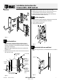
1
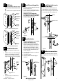
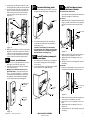
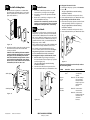
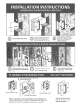
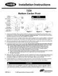
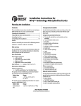
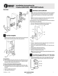
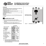
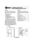
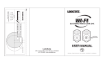
Installation Instructions for
V Series 34HV–35HV Locksets
Overview
2 Mark the vertical centerline of the lock on the door’s edge.
3 Mark the vertical centerline of the lock on both sides of the door as
measured from the vertical centerline on the door’s edge.
4 Mark the horizontal centerline of the strike on the door jamb 3/8“
above the horizontal centerline of the lock.
2
Position template
1 Cut the template along the dotted line and align the horizontal and
vertical arrows to the marked centerlines on the door.
2 Tape the template onto the door.
3 Center punch the drill points.
Figure 1
1
Mark centerlines
Note 1: If the door is a fabricated hollow metal door, determine
whether it is properly reinforced to support the lock. If the door reinforcement is not adequate, consult the door manufacturer for information on proper reinforcement.
Note 2: The suggested height from the floor to the centerline of the
knob/lever is 38“.
1 Mark the horizontal centerline of the lock on both sides of the door
and on the door’s edge.
Recommended
door/jam gap
~ 1/8“
Figure 3
3
Mortise for lock case and front
Mortise the edge of the door to accommodate the lock case and face
plate.
2 3/4“ backset
Mortise case
Vertical
centerline of
cylinder and
knob/lever
Centerline
of strike
1 1/2“
3/8“
Vertical centerline of
door edge and lock front
Figure 2
T61853/Rev – 1852819 ER-7991-1
Horizontal
centerline of
lock
Horizonal
centerline of
knob/lever
(recommended
height 38“ from
floor)
Figure 4
BEST ACCESS SYSTEMS
Indianapolis, Indiana
1
4
6
Drill holes
Caution: Check the lock for the correct
function, hand, and bevel before drilling.
Drill only those holes required for the function.
Wire hole
7/8“ dia.
Cylinder hole
1 1/4“ dia.
Install mounting plates
1 Insert the outside mounting plate through
the door and lock case.
2 Position the inside mounting plate opposite the outside mounting plate and screw
them securely in place.
Caution: Do not overtighten the
mounting plate screws. Overtightening
may compress the mortise cavity and
bind the locking mechanism.
8
Install trim hole inserts
and bushings
1 Insert the two trim hole inserts into the
upper trim hole on each side of the door.
2 Insert the two bushings into the wire hole
on each side of the door (see Figure 10).
Bushing
Knob/lever
hole
7/8“ dia.
Trim hole insert
Throughbolt holes
3/8“ dia.
Inside
mounting
plate
Figure 5—RH and RHRB hole pattern
Trim hole
5/8“ dia.
Outside
mounting
plate
Turn knob
hole
1/2–5/8“ dia.
Figure 8
Trim hole
5/8“ dia.
Wire hole
5/8“ dia.
7
1
Figure 6—LH and LHRB hole pattern
5
Install mortise case
1 Remove the faceplate from the mortise
case.
2 Install the mortise case while feeding the
motor wire and deadbolt sensing wire
(deadbolt function only) into the mortise
cavity and out the wire hole (see Figure 7).
Deadbolt
sensing
wire
2
3
4
Bushing
Trim hole insert
Install cylinder
Caution: A malfunction can occur if the
cylinder is threaded in too far.
Thread the concealed cylinder into the
lockset so that the groove around the cylinder head is even with the door surface.
Adjust the cylinder depth plus or minus
one turn so that the core, when installed in
the cylinder, will be flush with the outer
surface of the trim.
Secure the cylinder into the case with the
case set screw.
Secure the faceplate.
Check the cylinder and lock for proper
operation.
Concealed
cylinder
Figure 10
9
Make wire connections
1 Feed the outside wire harness connector
through the top wire hole (see Figure 11).
Case set
screw (inside)
Outside
wire harness
connector
Motor
wire
Mortise case
Figure 7
3 Secure the mortise case with the case
mounting screws.
T61853/Rev – 1852819 ER-7991-1
Figure 11
Figure 9
BEST ACCESS SYSTEMS
Indianapolis, Indiana
2
2 Temporarily rest the trim on the door by
inserting the trim studs into the stud holes.
3 From the inside of the door, connect the
motor connector and the optional deadbolt sensing connector to their mating
connectors from the circuit board (see
Figure 12).
11
Connect battery pack
1 Connect the battery pack to the connector
hanging inside the battery compartment.
13
Install inside and outside levers/knobs
For both levers and knobs
Unscrew the inside spindle one full turn to
allow the spindles to turn freely.
Outside wire
harness
Battery
pack
For levers
1 With the handle pointing toward the door
hinges, put the outside lever and spindles
into the lockset from the outside of the
door.
Set screw
Motor
connector
Deadbolt
sensing connector
Figure 12
4 Making sure that the connector is properly
aligned, connect the outside wire harness
connector to the lower right circuit board
connector in the inside trim. Press firmly
on the connector until it is fully seated.
10
Secure escutcheons
1 Pull the excess outside wire harness back
through to the outside of the door.
2 Position the inside and outside escutcheons onto the door.
3 Making sure that the trim does not
pinch the wires, secure the trim to the
door — but do not tighten — with the
combination mounting screw at the top
mounting hole and with the standard
screw at the bottom mounting hole.
Figure 14
2 Insert the battery pack into the battery
compartment so that the foam will face
the battery door.
Caution: If installing a lock with the
turn knob function, make sure that the
battery wires are not rubbing against
the turn knob retaining ring.
12
Install battery compartment door
1 Insert the tabs of the battery compartment
door into its mating slots and swing the
door closed.
2 Secure the battery compartment door with
the security screw. Tighten firmly.
Spindles
Figure 16
2 Slide the inside lever onto the inside spindle and secure it with the set screw.
3 Tighten the trim mounting screws (see
Figure 13).
4 Turn the levers to check that they operate
smoothly.
For knobs
1 From the outside of the door, put the outside knob and spindles into the lockset.
Combination
mounting
screw
Set screw cap
Set screw
Security
screw
Tabs
Standard
mounting
screw
2 Slide the inside knob onto the inside spindle and secure it with the set screw.
3 Push the set screw cap into the set screw
hole.
4 Tighten the trim mounting screws (see
Figure 13).
5 Turn the knobs to check that they operate
smoothly.
Figure 15
Figure 13
T61853/Rev – 1852819 ER-7991-1
Figure 17
BEST ACCESS SYSTEMS
Indianapolis, Indiana
3
14
Install strike plate
1 Mortise the door jamb to accommodate
the strike box and strike plate. (See Installation Specifications or dimensions, template V03 and H11.)
15
1 Insert the control key into the core and
rotate the key 15 degrees to the right.
2 Insert the core into the cylinder with the
control key.
3 Rotate the control key 15 degrees to the
left and withdraw the key.
Caution: The control key can be used to
remove cores and access doors. Provide
adequate security for the control key.
16
Figure 18
2 Insert the strike box into the mortise in the
door frame and secure the strike with
screws provided.
Caution: The auxiliary bolt must make
contact with the strike plate, as shown
in Figure 19. The auxiliary bolt deadlocks the latchbolt and prevents someone from forcing the latch open when
the door is closed. If the incorrect strike
is installed, a lock-in can occur.
Install core
Test lock
To test the lock for proper operation, use the
temporary operator card or personal identification number (PIN) that came with the lock.
This card or PIN is for temporary use only and
once permanent cards or PINs have been programmed for the lock, you should delete the
temporary cards or PINs.
These temporary operator cards and PINs will
only work on factory default V Series locks.
For details on programming the lock for
access control, refer to the V Series Intelligent
Programming Software User Manual or the
V Series Handheld Terminal User Manual.
For magnetic stripe card electronic locks
1 With the BEST logo facing toward you,
insert and remove the temporary operator
card (see Figure 20).
The green light flashes and the locking
mechanism unlocks.
2 Turn the lever/knob and open the door.
3 Insert and turn the key to unlatch the door.
For keypad electronic locks
1 Enter the temporary operator PIN 99998.
2 Press ✽.
The green light flashes and the locking
mechanism unlocks.
3 Turn the lever/knob and open the door.
4 Insert and turn the key to unlatch the door.
For proximity card electronic locks
1 Place the temporary operator card in front
of the proximity reader (see Figure 21).
The green light flashes and the locking
mechanism unlocks.
2 Turn the lever/knob and open the door.
3 Insert and turn the key to unlatch the door.
Figure 21
If the mechanism doesn’t unlock, refer to
the following table.
LEDs
1 long
tone
Strike plate
Auxiliary bolt
Denied Use the token at
a moderate
speed.
Green
stays
on
Denied Use the temporary operator
token, not the
temporary communication
token.
Green
flashes
Denied Connect the
motor wires.
Denied Connect the
battery and connect the outside wire
harness.
Figure 19
Figure 20
T61853/Rev – 1852819 ER-7991-1
Sounder Access You should…
BEST ACCESS SYSTEMS
Indianapolis, Indiana
4