1
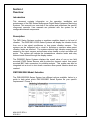
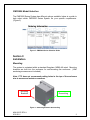
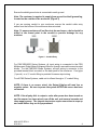
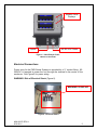
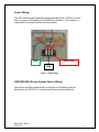
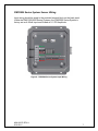
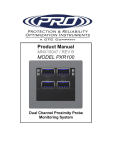
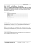
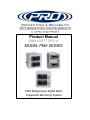
Product Manual MNX10037 / REV A MODEL PMX SERIES PRO Multipurpose Digital Meter Equipment Monitoring System Contents Section I Overview Introduction................................................................................ 2 Description................................................................................. 2 PMX1000/2000 Model Selection………..……………………….. 2 PMX3000 Model Selection…………..…..……………………….. 2 Section II Installation Mounting………......................................................................... 3 Electrical Connections…………………………………………….. 5 Power Wiring………………………………………………………. 5 PMX1000/2000 Series System Sensor Wiring………………… 6 PMX3000 Series System Sensor Wiring……………..………… 7 Section III Operation Configuring Relays..................................................................... 8 Analog Output…………………………………………………..….. 9 Section IV Maintenance General...................................................................................... 10 Warranty.................................................................................... 10 Figures Figure 1 (PMX1000/2000 Series Selection Guides).................. 2 Figure 2 (PMX3000 Series Selection Guides)........................... 3 Figure 3 (Mounting Brackets & Grounding)…………………….. 3 Figure 4 (Conduit Entry)………………………………………….. 4 Figure 5 (Cable Entry & Power)...……………….………………. 5 Figure 6 (Electrical Hazard)………………………………………. 5 Figure 7 (Power Entry)…………………………………………… 6 Figure 8 (PMX3000 Series System Input Wiring)……………… 7 MNX10037 REV A 8/31/2011 1 Section I Overview Introduction This document contains information on the operation, installation and maintenance of the PMX Series Multipurpose Digital Meter Equipment Monitoring Systems. This manual is an overview of the system and references the specific component manuals. User manuals are provided with the system for all configurable internal components. Description The PMX Series Systems monitors a machines condition based on its level of vibration. The PMX1000 & 2000 Series Systems will display the vibration levels from one or two signal conditioners or loop power vibration sensors. The systems can be integrated into a circuit to shutdown a machine when preset vibration levels are reached. The systems detects high vibration energy being sensed by the input sensors and actuates relays based on alert and alarm set points. The system will indicate the instantaneous vibration levels and relay status at each channel through the display meters. The PMX3000 Series Systems displays the overall value of one or two field mounted LP400 Series Sensors and provides the dynamic output from panel mounted BNC Jack connectors for portable analysis. This system can also be integrated into a circuit to shut down a machine when preset vibration levels are reached. PMX1000/2000 Model Selection The PMX1000/2000 Series System has different options available, below is a guide to help select which PMX1000/2000 Series System fits your specific requirements. (Figure 1) Figure 1 - PMX1000/2000 Series Selection Guide MNX10037 REV A 8/31/2011 2 PMX3000 Model Selection The PMX3000 Series System has different options available, below is a guide to help select which PMX3000 Series System fits your specific requirements. (Figure 2) Figure 2 - PMX3000 Series Selection Guide Section II Installation Mounting The system is contained within a standard fiberglass, NEMA 4X rated. Mounting brackets are built into the enclosure for wall-mounting the enclosure. (Wall anchoring screws are not included). Note: CTC does not recommend putting holes in the top of the enclosure due to access and moisture concerns. Mounting Brackets Ground Lug Figure 3 – Mounting Brackets & Grounding MNX10037 REV A 8/31/2011 3 Ensure the shield ground wire is connected to earth ground. Note: The customer is required to supply from ground to shield ground lug, located on the outside of the enclosure. (Figure 3) If you are running conduit to your enclosure, ensure the conduit cable entry enters from the bottom of the enclosure when mounted. Note: To ensure moisture will not flow into the enclosure, a hole should be drilled at the lowest point in the conduit to provide drainage for any moisture. Figure 4 – Conduit Entry For PMX1000/2000 Series Systems, all input wiring is connected to the PRO Multipurpose Digital Meter Equipment Monitor through removable screw terminal blocks. For the PMX3000 Series Systems, all input wiring is connector to the provided terminal block mounted on the back panel of the enclosure. Cord grips (1 per ch.) or a ½” conduit fitting is provided for sensor input wiring. For all PMX Series Systems, cable exit is offered through a ½” conduit fitting. NOTE: If there is no sensor wired, the Output Display will read low or negative values. Be sure to power the system AFTER the sensor has been connected. NOTE: If the display fails to output a value after power has been turned on and the sensor has been wired, turn off the unit, wait several seconds and then reapply power. The internal electronics require some time to ramp up and settle before they are fully operational. MNX10037 REV A 8/31/2011 4 Vibration Level Displays Inputs 85-265 VAC Power Figure 5 - Cable Entry & Power PMX3000-2-R-BA SHOWN Electrical Connections Power entry for the PMX Series Systems is provided by a ½” conduit fitting. 85265VAC is required to power the unit through the terminal in the center of the enclosure. See Figure 6 for power wiring. WARNING: Risk of Electrical Shock (Figure 6). WARNING: 85-265 VAC Figure 6 - Electrical Hazard MNX10037 REV A 8/31/2011 5 Power Wiring The PRO Multipurpose Digital Meter Equipment Monitor(s), PD765(s), will be wired for power in the factory for all PMX Series Systems. The customer is responsible for wiring the relays and input signals. GND 85‐265 VAC COM Figure 7 – Power Entry PMX1000/2000 Series System Sensor Wiring Input wiring should be wired directly to the back of the display relays as described in the PD765 Pro Universal Input Meter Instruction Manual. MNX10037 REV A 8/31/2011 6 PMX3000 Series System Sensor Wiring Input wiring should be wired to the provided terminal block on the back panel. Unlike the PMX1000/2000 Series Systems, the PMX3000 Series System is factory set as 4-20mA Input and Scaled at 0-1 IPS Amplitude. CH 2 Cable Drain Wire - GREEN WIRE CH 1 (+) Dynamic Velocity Output - WHITE WIRE (-) Common - BLACK WIRE (+) Loop Power mA Output - RED WIRE Figure 8 - PMX3000 Series System Input Wiring MNX10037 REV A 8/31/2011 7 Section III Operation Configuring Relays The input to the internal controller comes from a vibration transmitter. They are built with a specific full scale range and frequency band. Full scale range of the transmitters must be known in order for the controllers to display the correct vibration value. The transmitter will not display any vibration energy present at frequencies outside the filtering range. Manual adjustments to the Signal Conditioner may be required. Refer to PRO Signal Conditioner User Manual for specific instructions on calibration and operation. Example Full Scale 0 – 1.0 IPS, Frequency Band 10 – 1000 Hz. At 0 IPS, 0 Volts flow from the transmitter to the controller At 0.50 IPS, 2.5 Volts flow from the transmitter to the controller. At 1.0 IPS, 5 Volts flow from the transmitter to the controller. The monitoring channel provides 2 relay outputs. The system comes from the factory with a specific vibration range in IPS or mm/s. To configure the relay set points, this range must be known. It is recommended that baseline and typical alarm values of vibration are also known before setup is attempted. The relays provided by the internal controller are highly configurable. Refer to PD765 User Manual for detailed programming instructions. All of the following parameters can be adjusted: Relay Action – Automatic, Latching, Auto + Manual Reset, Latch with Clear. Relay Operation – Set and Reset points (Hysteresis), On and Off time Delays. MNX10037 REV A 8/31/2011 8 Example Setup 1: A full scale range of 0 – 1 IPS has been specified. Baseline Vibration on the machine to be monitored is 0.18 IPS-pk. Alarm and Shutdown levels of vibration are specified as 0.35 IPS-pk and 0.65 IPS-pk respectively, reset points are specified as 0.30 IPS-pk and 0.60 IPS-pk. Using the provided PD765 Process Controller Manual; Select relay operation and action desired, for this example we will have LOC, Latching Operation with Clear relays. Then program “Set 1” as 0.35 and “Set 2” as 0.65, then program reset points, “rST 1” as 0.30 and “rST 2” as 0.60. After relays have been programmed, scaling must be set. For this example, we will use a 0-5 Volt input with a 0-1 IPS display. Program “inP1” as 0.00, then “diS1” as 0.00, then “inP2” as 5.00, then “diS2” as 1.00. This will let us have an input of 0 Volts, display of 0.00 IPS and at an input of 5 Volts, 1.00 IPS will be displayed by the meter. The system will now actuate the LOC Relay (Relay 1) when the vibration level reaches 0.35 IPS-pk and another LOC Relay (Relay 2) when the vibration level reaches 0.65 IPS-pk. In order to reset the LOC relays, the vibration level must fall below the reset point of 0.60, then press the ACK for relay 2 and once the vibration level falls below 0.30, press the ACK to reset relay 1. Analog Output The analog 4-20 mA signal represents the amount of vibration energy present at each channel based on the transmitter’s full scale. I.E. a 12 mA signal from a 02.0 IPS transmitter represents a vibration level of 1.0 IPS. Obtaining the 4-20mA output from the controller may require manual adjustment of the SC Transmitters. Refer to PRO SC Transmitter user manual for specific instructions. Refer to PD765 User Manual for detailed programming instructions. MNX10037 REV A 8/31/2011 9 Section IV Maintenance Once the system has been calibrated and installed it requires minimal maintenance. Basic checks to ensure system integrity should be made periodically. Visual Inspections should include examinations for the following: The displays are operational No visible electrical burns or smoke inside the enclosure Enclosure hinges are free from rust and securely latched No moisture or condensation build up inside the enclosure General There are no customer replaceable parts. It should provide trouble-free continuous service under normal operating conditions. Warranty If any PRO product should ever fail, we will repair or replace it at no charge, as long as the product was not subjected to misuse, natural disasters, improper installation or modification which caused the defect. CONTACT INFORMATION: Connection Technology Center, Inc (CTC) 7939 Rae Blvd. Victor, NY 14564 1-800-999-5290 (US & Canada) 1-585-924-5900 (International) [email protected] – www.ctconline.com MNX10037 REV A 8/31/2011 10