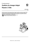
1
AXR Series Stage Hardware Manual
P/N: EDS168 (Revision 1.02.00)
Dedicated to the Science of Motion
Aerotech, Inc.
101 Zeta Drive,
Pittsburgh, PA 15238-2897
Phone: +1-412-963-7470
Fax: +1-412-963-7459
www.aerotech.com
Technical Support
Go to www.aerotech.com/service-and-support.aspx for information and support about your Aerotech
products. The website provides downloadable resources (such as up-to-date software, product manuals,
and Help files), training schedules, and PC-to-PC remote technical support. You can also complete Product
Return (RMA) forms and get information about repairs and spare or replacement parts.
For immediate help, contact a service office or your sales representative. Have your customer order number
available before you call or include it in your email.
United States
(World Headquarters)
Phone: +1-412-967-6440
Fax: +1-412-967-6870
Email: [email protected]
101 Zeta Drive
Pittsburgh, PA 15238-2897
www.aerotech.com
United Kingdom
Phone: +44 (0)1256 855055
Fax: +44 (0)1256 855649
Email: [email protected]
Japan
Phone: +81 (0)47 489 1741
Fax: +81 (0)47 489 1743
Email: [email protected]
Germany
Phone: +49 (0)911 967 9370
Fax: +49 (0)911 967 93720
Email: [email protected]
China
Phone: +86 (21) 3319 7715
Email: [email protected]
France
Phone: +33 1 64 93 58 67
Email: [email protected]
Taiwan
Phone: +886 (0)2 8751 6690
Email: [email protected]
N O T E : Aerotech continually improves its product offerings; listed options may be superseded at any
time. Refer to www.aerotech.com for the most up-to-date information.
N O T E : All drawings and illustrations are for reference only and were complete and accurate as of this
manual’s release. The most recent system drawings and schematics can be found on your software DVD
or on www.aerotech.com.
N O T E : Read this manual in its entirety before installing, operating, or servicing this product. If you do
not understand the information contained herein, contact an Aerotech representative before proceeding.
Strictly adhere to the statements given in this section and other handling, use, and operational information
given throughout the manual to avoid injury to you and damage to the equipment.
N O T E : This product is intended for light industrial manufacturing or laboratory use.
This manual contains proprietary information and may not be reproduced, disclosed, or used in whole or in
part without the express written permission of Aerotech, Inc. Product names mentioned herein are used for
identification purposes only and may be trademarks of their respective companies.
Copyright © 2010-2014 Aerotech, Inc. All rights reserved.
AXR Hardware Manual
Table of Contents
Table of Contents
Table of Contents
List of Figures
List of Tables
iii
iv
v
Chapter 1: Overview
1
1.1. Model Options
1.1.1. A Axis (Tilt) Drive Type Option
1.1.2. B Axis (Yaw) Mounting Location
1.1.3. Brake Option
1.1.4. Seal Option
1.1.5. Counterbalancing Kits
1.1.6. Manual Three Jaw Chuck
1.2. Dimensions
1.3. Safety Procedures and Warnings
1.4. EC Declaration of Incorporation
Chapter 2: Installation
2.1. Unpacking and Handling the Stage
2.2. Preparing the Mounting Surface
2.3. Securing the Stage to the Mounting Surface
2.4. Attaching the Payload to the Stage
2.4.1. B Axis With Tabletop Option
2.4.2. B Axis With Manual Three Jaw Chuck
2.5. Electrical Installation
Chapter 3: Operating Specifications
3.1. Environmental Specifications
3.2. Accuracy and Temperature Effects
3.3. Basic Specifications
3.4. Standard Motor Wiring
3.5. Limit Switches
3.6. Air Line Access
3.7. Brake Option
3.8. Drive Types
3.9. Counterbalance System
3.9.1. Offset Mounting Counterbalancing
3.9.2. Inline Mounting Counterbalancing
3.9.3. Balancing Charts
3.9.4. Balancing the A Axis
Chapter 4: Maintenance
3
4
4
4
4
4
4
5
7
8
9
9
11
12
13
13
14
15
17
17
17
18
20
24
25
26
26
27
27
28
29
36
39
4.1. Service and Inspection Schedule
4.2. Cleaning and Lubrication
4.3. Troubleshooting
39
40
41
Appendix A: Warranty and Field Service
43
Appendix B: Revision History
45
Index
47
www.aerotech.com
iii
Table of Contents
AXR Hardware Manual
List of Figures
Figure 1-1:
Figure 1-2:
Figure 2-1:
Figure 2-2:
Figure 2-3:
Figure 2-4:
Figure 3-1:
Figure 3-2:
Figure 3-3:
Figure 3-4:
Figure 3-5:
Figure 3-6:
Figure 3-7:
Figure 3-8:
Figure 3-9:
Figure 3-10:
Figure 3-11:
Figure 3-12:
Figure 3-13:
Figure 3-14:
Figure 3-15:
Figure 3-16:
Figure 3-17:
iv
AXR-100D Dimensions
AXR-150 Dimensions
AXR With Shipping Bracket
Mounting Hole Locations
Chuck Clamping Ranges
Electrical Connectors and Grounds
Limit Switch Wiring
Air Line Access
Brake Option: Air Line Access
Adjustable Counterweight Locations (Offset and Chuck Options)
Adjustable Counterweight Locations (-0E Option)
AXR100D-100 Balance Chart
AXR100D-0E Balance Chart
AXR100D-100C Balance Chart
AXR150D-125 Balance Chart
AXR150D-125C Balance Chart
AXR150D-0E Balance Chart
AXR150G50-125 Balance Chart
AXR150G100-125 Balance Chart
AXR150G160-125 Balance Chart
AXR150G50-125C Balance Chart
AXR150G100-125C Balance Chart
AXR150G160-125C Balance Chart
5
6
10
12
14
15
24
25
26
27
28
29
30
30
31
31
32
32
33
33
34
34
35
www.aerotech.com
AXR Hardware Manual
Table of Contents
List of Tables
Table 1-1:
Table 2-1:
Table 2-2:
Table 3-1:
Table 3-2:
Table 3-3:
Table 3-4:
Table 3-5:
Table 3-6:
Table 3-7:
Table 3-8:
Table 3-9:
Model Numbering System
Stage to Mounting Surface Hardware
Clamping Ranges for Self Centering Scroll Chucks
Environmental Specifications
AXR Series Specifications
Motor Specifications
Aerotech Motor and Feedback Cable Part Numbers
Motor Pin Assignments for the A and B Axes
Feedback Pin Assignments for the A Axis
Feedback Pin Assignments for the B Axis
Gear Drive Specifications
Continuous Current and Torque Ratings
www.aerotech.com
3
12
14
17
18
19
21
21
22
23
26
37
v
Table of Contents
vi
AXR Hardware Manual
www.aerotech.com
AXR Hardware Manual
Overview
Chapter 1: Overview
Aerotech’s AXR integrated two-axis rotary assembly provides high-speed machining capabilities for
complex 3D part geometries. The precision-aligned system allows accurate positioning on a hemispherical
surface. Multiple frame sizes with direct- or gear-driven options provide a wide range of load carrying
capability.
A Axis (Tilt)
l
l
l
l
l
l
B Axis (Yaw)
Multiple configurations support a range of load
and accuracy requirements
Integral rotary union for vacuum- or airactivated tooling
High-speed yaw axis provides up to 1000 rpm
High-load gear-drive or high-speed, direct-drive
tilt-axis configurations
Optional sealing protects the system from
airborne particulates
Brake available to limit stage motion in the
unpowered state
Direct-Drive Yaw Axis
All AXR series rotary combinations feature a direct-drive yaw (B) axis. Direct-drive motors exhibit
significantly higher throughput and maintenance-free operation when compared to gear- and screw-driven
technology. With peak rotation speeds of up to 1000 rpm, the AXR is capable of supporting high-speed
machining processes. A high-resolution encoder enables the axis to run at extremely slow speeds while
maintaining excellent velocity regulation and positioning accuracy.
High-Capacity Tilt Axis
The AXR has both direct-drive and gear-driven tilt (A) axis configurations to meet the performance
requirements of your specific application. The direct-drive version provides the highest possible operating
speed and accuracy for demanding applications. A modular counterbalance system and different yaw
mounting heights are available to balance offset loads. The tilt axis can be equipped with a brake to hold axis
position when power is removed. For large load applications, the gear-drive units provide significantly higher
continuous torque output while the drive mechanism limits motion in the power-off state. The precision antibacklash gearing enables this higher torque output while still maintaining excellent accuracy and
repeatability performance.
www.aerotech.com
Chapter 1
1
Overview
AXR Hardware Manual
Material Handling
The AXR comes standard with an integral rotary union that provides a single pneumatic control signal to the
yaw-axis tabletop for customer supplied air- or vacuum-actuated tooling. The AXR can also be outfitted with
a 3-jaw manual chuck for maximum part-holding flexibility.
Scalable Product Solutions
With both direct-drive and gear-driven platforms, various yaw table locations, a scalable counterbalance,
standard pneumatic feed-through, and an optional 3-jaw chuck, the AXR can be configured to meet the
requirements of most two-axis rotary assemblies.
This chapter introduces standard and optional features of the AXR A/B combination stage and gives general
safety precautions. The AXR is a two axis rotary assembly with pitch and yaw orientation.
2
Chapter 1
www.aerotech.com
AXR Hardware Manual
Overview
1.1. Model Options
N O T E : Aerotech continually improves its product offerings; listed options may be superseded at any
time. Refer to www.aerotech.com for the most up-to-date information.
Table 1-1:
Model Numbering System
Stage Size
-100D
Direct-drive tilt (A) axis and yaw (B) axis rated for 15 kg maximum load
-150D
Direct-drive tilt (A) axis and yaw (B) axis rated for 30 kg maximum load
-150G
Gear-drive tilt (A) axis with direct-drive yaw (B) axis; rated for 30 kg maximum load
Yaw Axis Configuration
Yaw (B) axis tabletop height of AXR100D and AXR150x located at the center of rotation of the
-0
tilt (A) axis; no counterweight attachment supported
Yaw (B) axis tabletop height of AXR100D and AXR150D located at the center of rotation of the
-0E
tilt (A) axis; includes attachment features for counterweights to balance offset loads
NOTE: 0E option not available on gear-driven AXRs (150G). Gearbox has sufficient holding torque to balance
maximum moment load.
Yaw (B) axis tabletop height for AXR100D is located 100 mm above the center of rotation of
-100
the tilt (A) axis; includes attachment features for counterweights to balance offset loads
Yaw (B) axis with 3-jaw 3.25-inch (82.6 mm) diameter manual scroll chuck; chuck jaws of
-100C
AXR100D are located 100 mm above the center of rotation of the tilt (A) axis; includes
attachment features for counterweights to balance offset loads and 3-jaw manual chuck
Yaw (B) axis tabletop height for AXR150x is located 125 mm above the center of rotation of
-125
the tilt (A) axis; includes attachment features for counterweights to balance offset loads
Yaw (B) axis with 3-jaw 5-inch (127 mm) diameter manual scroll chuck; chuck jaws of
-125C
AXR150x are located 125 mm above the center of rotation of the tilt (A) axis; includes
attachment features for counterweights to balance offset loads and 3-jaw manual chuck
Brake Configuration (Optional)
-B
Holding brake for tilt (A) axis; only available on 100D and 150D configurations
Sealing Configuration (Optional)
Seals on the tilt (A) and yaw (B) axes to prevent ingress of airborne particulates into the stage;
-S
the seal does not protect the AXR system from contact with fluids
Counterweight Configuration (Optional)
Counterweight kit for AXR100 (-100, -100C) for offset loads ranging from:
-CCW1
-100: 23.5 N·m to 338 N·m
-100c: 48 N·m to 242 N·m
Counterweight kit for AXR100 (-100, -100C) for offset loads ranging from:
-CCW2
-100: 1.4 N·m to 48 N·m
-100c: 6 N·m to 36 N·m
-CCW3
Counterweight kit for AXR100 (-100) for offset loads of 41.3 N·m
-CCW4
Counterweight kit for AXR100 (-100C) for offset loads of 23.4 N·m
-CCW5
Counterweight kit for AXR100 (-0E) for offset loads ranging from 10.8 N·m to 54.2 N·m
-CCW6
Counterweight kit for AXR100 (-0E) for offset loads ranging from 31.1 N·m to 124.4 N·m
-CCW7
Counterweight kit for AXR100 (-0E) for offset loads of 15.7 N·m
-CCW8
Counterweight kit for AXR100 (-0E) for offset loads of 13.1 N·m
(1) Offset loads include both the payload and stage unbalance.
(2) A linear combination of counterweight kits can be employed to achieve balance. Refer to Section 3.9.3.
determine if application falls within balance limits.
www.aerotech.com
Chapter 1
3
Overview
AXR Hardware Manual
1.1.1. A Axis (Tilt) Drive Type Option
The AXR has both direct drive and gear driven tilt (A) axis configurations. The direct drive version provides
the highest possible operating speed and accuracy for demanding applications. For large load applications
the gear drive units provide significantly higher continuous torque output while the drive mechanism limits
motion in the power off state. The precision, anti-backlash gearing enables this higher torque output while
still maintaining excellent accuracy and repeatability performance.
Both the direct drive and gear drive versions of the A axis have the same footprint and mounting pattern, so a
common design will interface with either stage.
1.1.2. B Axis (Yaw) Mounting Location
Two different B-axis mounting locations are available to accommodate various payload sizes as well as
workpiece holding. This option allows the B axis interface surface to be either inline with the A (tilt) axis of
rotation or above the A axis of rotation. These orientations are referred to as "inline" and "offset" mounting,
respectively, in the remainder of this manual. You can use the balancing charts in Section 3.9.3. to
determine the merits of each mounting option.
1.1.3. Brake Option
The direct drive Tilt axis can be equipped with a brake to hold the axis in position when power is removed.
This option does not affect the footprint of the product.
1.1.4. Seal Option
The AXR series stages are available with optional internal sealing to provide IP60 level dust protection.
AXR stages are not rated for exposure to liquids. These seals are internal and do not require maintenance.
1.1.5. Counterbalancing Kits
A modular counterbalance system is available to balance offset loads. These ktis are intended to balance
the combined mass of the B axis stage and the customer payload about the axis of rotation of the A axis.
N O T E : These kits are necessary for the direct drive Tilt axis and, to a lesser extent, the gear drive Tilt
axis.
1.1.6. Manual Three Jaw Chuck
The AXR can be outfitted with a three jaw manual chuck for maximum part holding flexibility. This option
provides an payload interface offset at the same elevation as that of the standard tabletop.
4
Chapter 1
www.aerotech.com
AXR Hardware Manual
Overview
1.2. Dimensions
N O T E : Aerotech continually improves its product offerings; listed options may be superseded at any
time. Refer to www.aerotech.com for the most up-to-date information.
CUSTOMER PNEUMATIC SUPPLY
M5-0.8 THREAD
(NOT AVAILABLE ON -100C)
4X
15 SLOTTED
7 THRU
STAGE MOUNTING HOLES
85 B.C.
110
215 200
A
&86720(502817,1*
;0+(/,&2,/ (48$//<63$&('21%&
70
100
150.7
DETAIL A
SCALE 1 : 5
170
CUSTOMER PNEUMATIC SUPPLY
TO TABLETOP, 4MM OD FITTING
(NOT AVAILABLE ON -100C)
375.7
13° Limit
259.7
MOTOR/FEEDBACK
A-AXIS
103° Limit
100
2° HS
2° HS
176
91
MOTOR/FEEDBACK
B-AXIS
320.7
BRAKE SUPPLY PRESSURE,
4MM OD FITTING
(-B OPTION ONLY)
54 (-0, -0E)
55 (-100, -100C)
B-AXIS RADIAL CLEARANCE
WITH RESPECT TO A-AXIS MOTION
289 (-0, -0E)
291 (-100, -100C)
14
14
100
( -100 ) B-AXIS TABLETOP 100MM FROM
A-AXIS CENTER OF ROTATION
( -0 ) B-AXIS TABLETOP ON
A-AXIS CENTER OF ROTATION
3 INCH MANUAL CHUCK
95
14
100
( -0E ) B-AXIS TABLETOP ON
A-AXIS CENTER OF ROTATION, WITH
EXTENDED YOKE COUNTERBALANCE
( -100C ) TABLETOP OF CHUCK 100MM FROM
A-AXIS CENTER OF ROTATION
DIMENSIONS: MILLIMETERS
Figure 1-1:
www.aerotech.com
AXR-100D Dimensions
Chapter 1
5
Overview
AXR Hardware Manual
CUSTOMER PNEUMATIC SUPPLY
M5x0.8 THREAD
(NOT AVAILABLE ON -125C)
85 B.C.
15 SLOTTED
4X
7 THRU
STAGE MOUNTING HOLES
A
265
DETAIL A
SCALE 2 : 15
170
240
CUSTOMER MOUNTING
8X M6-1.0 HELICOIL
6.0
EQUALLY SPACED ON B.C.
81.5
195.5
100
CUSTOMER PNEUMATIC SUPPLY
TO TABLETOP - 4MM OD FITTING
(NOT AVAILABLE ON -125C)
220
MOTOR/FEEDBACK
A-AXIS
BRAKE SUPPLY PRESSURE
4MM OD FITTING
(-B OPTION ONLY)
462
286
15° Limit
135
105° Limit
3° HS
3° HS
226
116
MOTOR/FEEDBACK
B-AXIS
62
356
B-AXIS RADIAL CLEARANCE
WITH RESPECT TO A-AXIS MOTION
377
13
13
125
(-125) B-AXIS TABLETOP MEASURED
FROM CENTERLINE OF A-AXIS
(-0) B-AXIS TABLETOP ON
A-AXIS CENTER OF ROTATION
5 INCH MANUAL CHUCK
13
125
125
(-0E) B-AXIS TABLETOP ON
A-AXIS CENTER OF ROTATION, WITH
EXTENDED YOKE COUNTERBALANCE
Figure 1-2:
6
(-125C) TABLETOP OF CHUCK MEASURED
FROM CENTERLINE OF A-AXIS
DIMENSIONS: MILLIMETERS
AXR-150 Dimensions
Chapter 1
www.aerotech.com
AXR Hardware Manual
Overview
1.3. Safety Procedures and Warnings
The following statements apply wherever the Warning or Danger symbol appears within this manual. Failure
to observe these precautions could result in serious injury to those individuals performing the procedures
and/or damage to the equipment.
D A N G E R : This product contains potentially lethal voltages. To reduce the possibility of
electrical shock, bodily injury, or death the following precautions must be followed.
1. Access to all AXR and component parts must be restricted while connected to a power
source.
2. Do not connect or disconnect any electrical components or connecting cables while
connected to a power source.
3. Disconnect electrical power before making any mechanical adjustments or performing
maintenance.
4. Make sure AXR and all components are properly grounded in accordance with local
electrical safety requirements.
5. Operator safeguarding requirements must be addressed during final integration of the
product.
W A R N I N G : To minimize the possibility of electrical shock, bodily injury or death the
following precautions must be followed.
1. Moving parts can cause crushing or shearing injuries. Access to all stage and motor parts
must be restricted while connected to a power source.
2. Cables can pose a tripping hazard. Securely mount and position all system cables to avoid
potential hazards.
3. Do not expose the AXR to environments or conditions outside the specified range of
operating environments. Operation in conditions other than those specified can cause
damage to the equipment.
4. The AXR must be mounted securely. Improper mounting can result in injury and damage
to the equipment.
5. Use care when moving the AXR. Lifting or transporting the AXR can result in injury or
damage to the AXR.
6. The AXR is intended for light industrial manufacturing or laboratory use. Use of the AXR
for unintended applications can result in injury and damage to the equipment.
7. If the AXR is used in a manner not specified by the manufacturer, the protection provided
by the AXR can be impaired and result in damage, shock, injury, or death.
8. Operators must be trained before operating this equipment and all service and
maintenance must be performed by qualified personnel.
9. All service and maintenance must be performed by qualified personnel.
www.aerotech.com
Chapter 1
7
Overview
AXR Hardware Manual
1.4. EC Declaration of Incorporation
Manufacturer: Aerotech, Inc.
101 Zeta Drive
Pittsburgh, PA 15238-2897
USA
herewith declares that the product:
AXR Stage
is intended to be incorporated into machinery to constitute machinery covered by the Directive
2006/42/EC as amended;
does therefore not in every respect comply with the provisions of this directive;
and that the following harmonized European standards have been applied:
EN ISO 12100
Safety of machinery - Basic concepts, general principles for design
EN 60204-1
Safety of machinery - Electrical equipment of machines - Part 1: General requirements
and further more declares that
it is not allowed to put the equipment into service until the machinery into which
it is to be incorporated or of which it is to be a component has been found and
declared to be in conformity with the provisions of the Directive 2006/42/EC and
with national implementing legislation, i.e. as a whole, including the equipment
referred to in this Declaration.
Authorized Representative:
Address:
Name
Position
Location
Date
8
Manfred Besold
AEROTECH GmbH
Süd-West-Park 90
D-90449 Nürnberg
/ Alex Weibel
Engineer Verifying Compliance
Pittsburgh, PA
April 17, 2014
Chapter 1
www.aerotech.com
AXR Hardware Manual
Installation
Chapter 2: Installation
This chapter describes the installation procedure for the AXR stage, including handling the stage, preparing
the mounting surface to accept the stage, securing the stage to the mounting surface, attaching the payload,
and making the electrical connections.
W A R N I N G : AXR installation must be in accordance to instructions provided by this manual
and any accompanying documentation. Failure to follow these instructions could result in injury
and damage to the equipment.
2.1. Unpacking and Handling the Stage
Carefully remove the AXR from the protective shipping container. Before operating the AXR, it is important
to let the AXR stabilize at room temperature for at least 12 hours. Allowing the AXR to stabilize to room
temperature will ensure that all of the alignments, preloads, and tolerances are the same as they were when
tested at Aerotech. Use compressed nitrogen or clean, dry, oil-less air to remove any dust or debris that has
collected during shipping. Set the AXR on a smooth, flat, and clean surface.
Each AXR has a label listing the system part number and serial number. These numbers contain information
necessary for maintaining or updating system hardware and software. Locate this label and record the
information for later reference. If any damage has occurred during shipping, report it immediately.
All AXR series stages are packaged with shipping brackets installed to prevent unwanted stage motion and
potential damage from occurring during shipment. The brackets are red anodized aluminum (the only red
anodized pieces Aerotech uses) that bolt the stage table to the base and they must be removed from the
stage before the stage can be operated. The shipping bracket is located on the cable side of the A axis (refer
to Figure 2-1). Retain the brackets for future use.
W A R N I N G : Make sure that all moving parts are secure before moving the AXR. Unsecured
moving parts may shift and cause bodily injury.
W A R N I N G : Lift the AXR only by the base. Improper handling could adversely affect the
AXR’s performance.
W A R N I N G : Do not use the tabletop or cable as lifting points.
W A R N I N G : Use care when moving the AXR. Lifting or transporting the AXR can result in
injury or damage to the AXR.
www.aerotech.com
Chapter 2
9
Installation
AXR Hardware Manual
Figure 2-1:
AXR With Shipping Bracket
N O T E : Retain any shipping brackets for future use. In the event the stage requires service at the
factory, the shipping bracket should be reattached to ensure the stage ships safely.
10
Chapter 2
www.aerotech.com
AXR Hardware Manual
Installation
2.2. Preparing the Mounting Surface
The mounting surface must be flat and have adequate stiffness in order to achieve the maximum
performance from the AXR. When the AXR is mounted to a non-flat surface, the stage can be distorted as
the mounting screws are tightened. This distortion will decrease the overall accuracy of the stage.
Adjustments to the mounting surface must be done before the stage is secured.
N O T E : To maintain accuracy, the mounting surface must be flat within 1 µm per 50 mm.
N O T E : The AXR is precision machined and verified for flatness prior to product assembly at the factory.
If machining is required to achieve the desired flatness, it should be performed on the mounting surface
rather than the AXR. Shimming should be avoided if possible. If shimming is required, it should be
minimized to improve the rigidity of the system.
W A R N I N G : Make sure that all moving parts are secure before moving the AXR. Unsecured
moving parts may shift and cause bodily injury.
www.aerotech.com
Chapter 2
11
Installation
AXR Hardware Manual
2.3. Securing the Stage to the Mounting Surface
AXR series stages have a fixed mounting pattern in the housing of the stage (as shown in Figure 2-2 and
Section 1.2.). Refer to Table 2-1 for mounting hardware information.
Table 2-1:
Stage to Mounting Surface Hardware
Mounting Hardware
M6x1.0 x 20 mm long [1/4-20 x 3/4 in long] SHCS (1)
1.
2.
Quantity
Screw Torque
4 places
(Figure 2-2)
8.0 N·m (6.6 ft·lb)
Socket Head Cap Screw
Refer to Section 1.2. for specific model mounting locations and dimensions
W A R N I N G : The AXR must be mounted securely. Improper mounting can result in injury
and damage to the equipment.
Figure 2-2:
12
Mounting Hole Locations
Chapter 2
www.aerotech.com
AXR Hardware Manual
Installation
2.4. Attaching the Payload to the Stage
The payload attachment method varies depending on whether the B axis is equipped with a tabletop or with a
three jaw chuck. Section 2.4.1. and Section 2.4.2.explain the different attachment methods in more detail.
AXR stages typically require some level of payload balancing to keep the holding torque required of the A
axis drive train to an acceptable level. Depending on the options of the unit, is possible that, before you can
run the stage, you must install a payload to match the balancing of the system as it was shipped. Aerotech
recommends starting the stage for the first time using a dummy payload attached that has the same mass
and center of gravity as the final payload that is to be used with the system. Once the servo tuning and
operating parameters are set to satisfaction, then the final payload should be installed.
For high speed operation of the B axis, payloads must be balanced to G1.0 per ISO 1940.
2.4.1. B Axis With Tabletop Option
Payloads can be bolted to the B axis tabletop via the threaded holes with Helicoil inserts. Hole pattern
details are shown in Figure 1-1 and Figure 1-2.
N O T E : For valid system performance, the mounting interface should be flat within 10 microns or less.
W A R N I N G : Do not attach a payload to the stage table with screws that are too long. A
screw extending through the stage table can affect travel and damage the stage. Refer to
Section 1.2. for maximum thread dimensions.
You can access the pneumatic line via the M5 tapped hole in the center of the table top. An o-ring (568A-015)
is also available as a static thrust seal on the table top for direct feed through of the pneumatic line to a
payload.
www.aerotech.com
Chapter 2
13
Installation
AXR Hardware Manual
2.4.2. B Axis With Manual Three Jaw Chuck
The three jaw chuck option consists of a manual scroll chuck with three stepped jaws. The chuck is
centered on the B axis at the factory to within 13 microns. Figure 1-1 and Figure 1-2 show the general stage
layout with the -100C and -150C chuck options.
The jaws can be positioned to provide a wide range of clamping capacity as shown in Figure 2-3 and Table 22. A scroll key is provided with the stage for opening and closing the jaws.
Figure 2-3:
Table 2-2:
Chuck Clamping Ranges
Clamping Ranges for Self Centering Scroll Chucks
Model
Chuck Diameter
inch
mm
AXR100
AXR150
3 1/4
5
80
125
d1
d2
2.0 to 26.9
3.0 to 50.0
22.1 to 46.0
34.8 to 73.9
d3
mm
45.0 to 69.1
71.9 to 115.1
d4
d5
24.9 to 50.0 48.0 to 71.1
39.1 to 83.1 80.0 to 125.0
Allowable clamping force varies with the structure of the payload. Be sure that the clamping force imparted
on the workpiece is sufficient to hold the part in place before operating the stage.
14
Chapter 2
www.aerotech.com
AXR Hardware Manual
Installation
2.5. Electrical Installation
W A R N I N G : Electrical installation must be performed by properly qualified personnel.
Aerotech motion control systems are adjusted at the factory for optimum performance. When the AXR is
part of a complete Aerotech motion control system, setup usually involves connecting a stage to the
appropriate drive chassis with the cables provided. Labels on the system components usually indicate the
appropriate connections.
Refer to the appropriate system manuals and documentation included on the software DVD for additional
installation and operation information. If the system is uniquely configured, a drawing showing system
interconnects is supplied.
The electrical wiring from the motor and encoder are integrated at the factory. Refer to Section 3.4. for
standard motor wiring and connector pin outputs.
W A R N I N G : Applications requiring access to the stage while it is energized will require
additional grounding and safeguards. The System Integrator or qualified installer is responsible
for determining and meeting all safety and compliance requirements necessary for the
integration of this stage into the final application.
D A N G E R : Remove power before connecting or disconnecting electrical components or
cables. Failure to do so may cause electric shock.
W A R N I N G : Operator access to the base and table top must be restricted while connected
to a power source. Failure to do so may cause electric shock.
Figure 2-4:
Electrical Connectors and Grounds
N O T E : Refer to the controller documentation to adjust servo gains for optimum velocity and position
stability.
www.aerotech.com
Chapter 2
15
Installation
16
AXR Hardware Manual
Chapter 2
www.aerotech.com
AXR Hardware Manual
Operating Specifications
Chapter 3: Operating Specifications
The surrounding environment and operating conditions can affect the performance and service life of the
stage. This chapter provides information on ideal environmental and operating conditions as well as general
technical information about AXR series stages.
3.1. Environmental Specifications
The environmental specifications for the AXR are listed in the following table.
Table 3-1:
Environmental Specifications
Ambient
Temperature
Humidity
Altitude
Vibration
Dust Exposure
Use
Operating: 10° to 35° C (50° to 95° F)
The optimal operating temperature is 20° C ±2° C (68° F ±4° F). If at any time the
operating temperature deviates from 20° C degradation in performance could occur.
Contact Aerotech for information regarding your specific application and environment.
Storage: 0° to 40° C (32° to 104° F) in original shipping packaging
Operating: 20% to 60% RH
Storage: 10% to 70% RH, non-condensing in original packaging
Operating: 0 m to 2,000 m (0 ft to 6,562 ft) above sea level
Contact Aerotech if your specific application involves use above 2,000 m or below sea
level.
Use the system in a low vibration environment. Excessive floor or acoustical vibration
can affect system performance. Contact Aerotech for information regarding your
specific application.
With the seal option, AXR stages are dust sealed but should not be exposed to water.
This equates to an ingress protection rating of IP60.Without the seal option, AXR
stages are not suited for dusty or wet environments. This equates to an ingress
protection rating of IP00.
Indoor use only
W A R N I N G : Do not expose the AXR to environments or conditions outside the specified
range of operating environments. Operation in conditions other than those specified can cause
damage to the equipment.
3.2. Accuracy and Temperature Effects
Aerotech products are designed for and built in a 20°C (68°F) environment. Extreme temperature changes
could cause a decrease in performance or permanent damage to the AXR. The environmental temperature
must be controlled to within 0.25ºC per 24 hours to ensure the AXR specifications are repeatable over an
extended period of time. The severity of temperature effects on all specifications depends on many different
environmental conditions, including how the AXR is mounted. Contact the factory for more details.
www.aerotech.com
Chapter 3
17
Operating Specifications
AXR Hardware Manual
3.3. Basic Specifications
N O T E : Aerotech continually improves its product offerings; listed options may be superseded at any
time. Refer to www.aerotech.com for the most up-to-date information.
Table 3-2:
AXR Series Specifications
Mechanical
Specifications
AXR-100
Tilt (A) Axis Yaw (B) Axis
Direct Drive Direct Drive
Travel
+10° to -100°
Unlimited
Uncalibrated
±145 µrad (±30 arc sec)
Calibrated
±14.5 µrad (±3 arc sec)
Accuracy(1)
Resolution
Repeatability(1) (BiDirectional)
Tilt Error Motion
Axial Error Motion
Radial Error Motion
Orthogonality
Axis Intersection
0.05 arc·sec
0.08 arc·sec
1 arc·sec
N/A
5 arc·sec
N/A
1.5 µm
N/A
3 µm
50 µrad (10 arc-sec)
±10 µm (± 0.00039 in)
Gear Ratio
N/A
Maximum Speed(6)
720 °/sec
1000 rpm
Maximum Torque
(Continuous)
4.18 N·m
0.2 N·m
Load Capacity
Rotor Inertia
(Unloaded)
Stage Mass
(6)
15 kg
No Offset
Offset
Chuck
Option
No Offset
Offset
Chuck
Option
Material
Mean Time Between Failure
Tilt (A) Axis
Direct Drive
AXR-150
Tilt (A) Axis
Gear Drive
Yaw (B) Axis
Direct Drive
+10° to -100°
±145 µrad
(±30 arc sec)
±14.5 µrad
(±30 arc sec)
0.04 arc·sec
+10° to -100°
±242 µrad
(±50 arc sec)
±24.2 µrad
(±50 arc sec)
0.04 arc·sec
Unlimited
±145 µrad
(±30 arc sec)
±14.5 µrad
(±30 arc sec)
0.05 arc·sec
1 arc·sec
5 arc·sec
1 arc·sec
N/A
N/A
N/A
N/A
3 arc·sec
N/A
1 µm
N/A
2 µm
50 µrad (10 arc-sec)
±10 µm (± 0.00039 in)
51:1
N/A
101:1
N/A
161:1
60 °/s
720 °/sec
30 °/s
600 rpm
18 °/s
305 N·m
11.12 N·m
605 N·m
2.36 N·m
964 N·m
30 kg
0.216 kg·m2
0.211 kg·m2
0.178 kg·m2
0.174 kg·m2
0.00686
kg·m2
2
2
0.212 kg·m
0.207 kg·m
0.070 kg·m2
0.00107
kg·m2
24 kg
24.4 kg
N/A
N/A
45.5 kg
46.8 kg
44 kg
45.5 kg
N/A
N/A
24.9 kg
N/A
50.7 kg
49.4 kg
N/A
Aluminum
20,000 Hours
20,000 Hours
Aluminum
15,000
Hours
20,000 Hours
(1) Certified with each stage.
(2) On-axis loading is listed
(3) All error motion specifications are measured at 60 rpm.
(4) For high speed operation, customer payload must be balanced to G1.0 per ISO 1940.
(5) Max speed is listed for unloaded stages. Max speed of gear drive unit is a function of gear ratio. Speeds are
10 rpm, 5 rpm, and 3 rpm.
(6) Stage mass listed as system mass.
18
Chapter 3
www.aerotech.com
AXR Hardware Manual
Table 3-3:
AXR
100-D
150-D
150-G-50
150-G-100
150-G-160
Operating Specifications
Motor Specifications
Tilt (A)
Axis
Motor(1)
Yaw (B)
Axis Motor
S-130-60-A
S-180-69-A
S-180-44-A
S-180-44-A
S-180-44-A
S-76-35-AH
S-130-39-A
S-130-39-A
S-130-39-A
S-130-39-A
(1)
Tilt (A) Axis
Current(2)
Cont. Peak
3.4
13.6
5.1
20.4
2.7
10.8
2.7
10.8
2.7
10.8
Yaw (B) Axis
Current(2)
Cont. Peak
2
8
3.8
15.2
3.8
15.2
3.8
15.2
3.8
15.2
Tilt (A)
Axis Wire
Gauge
Yaw (B)
Axis Wire
Gauge
#20
#18
#22
#22
#22
#22
#20
#20
#20
#20
(1) All motors rated for 340 VDC.
(2) All currents listed in Apk.
www.aerotech.com
Chapter 3
19
Operating Specifications
AXR Hardware Manual
3.4. Standard Motor Wiring
Stages fitted with standard motors and encoders come from the factory completely wired and assembled.
N O T E : Refer to the other documentation accompanying your Aerotech equipment. Call your Aerotech
representative if there are any questions on system configuration.
N O T E : If using standard Aerotech motors and cables, motor and encoder connection adjustments are
not required.
The AXR's protective ground connection provides motor frame ground protection only. Additional grounding
and safety safeguards are required for applications requiring access to the stage while it is energized. The
System Integrator or qualified installer is responsible for determining and meeting all safety and compliance
requirements necessary for the integration of this stage into the final application.
D A N G E R : Remove power before connecting or disconnecting electrical components or
cables. Failure to do so may cause electric shock.
W A R N I N G : The protective ground connection must be properly installed to minimize the
possibility of electric shock.
W A R N I N G : Operator access to the base and table top must be restricted while connected
to a power source. Failure to do so may cause electric shock.
C A U T I O N : The stage controller must provide over-current and over-speed protection.
Failure to do so may result in permanent damage to the motor and stage components.
20
Chapter 3
www.aerotech.com
AXR Hardware Manual
Operating Specifications
For cable drawings, refer to the software DVD that shipped with your system. For cables, drives, or
configurations not shown in Table 3-4, consult Aerotech.
Table 3-4:
AXR
Aerotech Motor and Feedback Cable Part Numbers
HPe, HLe, CP, CL, ML, MP
Motor
Feedback
(10)
C16501
C19360(1)
C165011(11)
C19363(2)
C16505(12)
C19364(3)
C16507(14)
C21031(4)
C165010(15)
(1) Over Molded Preferred
(2) Standard
(3) Standard (<450 dm)
(4) Hi-Flex Life
(5) Hi-Flex Life (<450 dm)
Table 3-5:
Motor
C21491(2)
C21511(6)
C22091(7)
(6) Lutze Hi-Flex (5 A)
(7) Gore Hi-Flex Life
(8) Standard (10 A)
(10) Standard (<120 dm)
(11) Configured (<120 dm)
Feedback
C16501(10)
C165011(11)
C16505(12)
C16507(14)
C165010(15)
Npaq, Npaq MR, Epaq MR
Motor
Feedback
(10)
C16501
C19803(2)
C165011(11)
C19804(3)
C16505(12)
C19802(4)
C16507(14)
C20111(5)
C165010(15)
(12) Standard (<240 dm)
(17) To Aux I/O Sec. Encoder
(13) Standard (<400 dm)
(18) CMD-9 to 25D Adapter
(14) Lutze Hi-Flex Life
(19) 25D Fdbk to Stage Combo. D
(15) Lutze Hi-Flex Life Configured
(16) Standard Configured (<225 dm)
Motor Pin Assignments for the A and B Axes
A3
MTR ØC (Motor Phase C)
1
Motor Shield (EMI shield)
2
Reserved: Not Used
3
Reserved: Not Used
4
Reserved: Not Used
5
Reserved: Not Used
A4
MTR ØB (Motor Phase B)
1 2
A2
A3
MTR ØA (Motor Phase A)
A2
A1
Connector
A1
Description
3 4 5
Pin
A4
Epaq
Frame Ground (motor protective ground)
Mating Connector
Aerotech P/N
Third Party P/N
Backshell
Sockets [QTY. 4]
Connector
ECK00656
ECK00659
ECK00657
Amphenol #17-1726-2
ITT Cannon #DM53744-6
ITT Cannon #DBMM9W4S
www.aerotech.com
Chapter 3
21
Operating Specifications
Table 3-6:
Pin
1
2
3
5
6
7
10
11
12
14
15
16
17
18
20
21
24
AXR Hardware Manual
Feedback Pin Assignments for the A Axis
Description
Connector
Signal shield connection
Over-Temperature Thermistor sensor
+5 V power supply input (internally connected to Pin 16) (the typical requirement is
250 mA).
Hall Effect sensor, phase B
Marker-N
Marker
Hall Effect sensor, phase A
Hall Effect sensor, phase C
Signal indicating maximum travel produced by positive/CW stage direction.
Cosine
Cosine-N
+5 V power supply input (internally connected to Pin 3)
Sine
Sine-N
Common ground (internally connected to Pin 21)
Common ground (internally connected to Pin 20)
Signal indicating maximum travel produced by negative/CCW stage direction.
14
25
1
13
(1) Pins not listed are RESERVED.
Mating Connector
Backshell
Connector
22
Aerotech P/N
Third Party P/N
ECK00656
ECK00300
Amphenol #17-1726-2
Cinch DB-25S
Chapter 3
www.aerotech.com
AXR Hardware Manual
Table 3-7:
Pin
1
2
3
5
6
7
10
11
14
15
16
17
18
20
21
Operating Specifications
Feedback Pin Assignments for the B Axis
Description
Connector
Signal shield connection
Over-Temperature Thermistor sensor
+5 V power supply input (internally connected to Pin 16) (the typical requirement
is 250 mA).
Hall Effect sensor, phase B
Marker-N
Marker
Hall Effect sensor, phase A
Hall Effect sensor, phase C
Cosine
Cosine-N
+5 V power supply input (internally connected to Pin 3)
Sine
Sine-N
Common ground (internally connected to Pin 21)
Common ground (internally connected to Pin 20)
14
25
1
13
NOTE: Pins not listed are RESERVED.
Mating Connector
Backshell
Connector
www.aerotech.com
Aerotech P/N
Third Party P/N
ECK00656
ECK00300
Amphenol #17-1726-2
Cinch DB-25S
Chapter 3
23
Operating Specifications
AXR Hardware Manual
3.5. Limit Switches
Limit switches signal when a stage has reached its maximum useable CW/Positive or CCW/Negative travel
distance. The limit switches are open-collector, TTL-compatible, active devices that are factory-configured
as Normally Closed (NC). The limit switches can be interfaced to 5V logic inputs.
Assuming a controller with a 5V input and an NC stage (current-sinking mode) limit configuration, the switch
state is closed, or logic 0 (typical 0.4V @ 12.8 mA), when no limit condition is present. When the limit switch
is activated, it opens and a 5V source through a pull-up resistor on the controller causes a logic 1 (typically
4.8-5 V) to be seen by the controller input.
The switch represented in Figure 3-1 is a PNP transistor.
W A R N I N G : If the AXR is driven beyond the electrical limit, it will encounter a mechanical
stop. Although the operating speed of the AXR may be relatively slow, impacting the
mechanical stop could cause damage to the stage.
CW/+ MACHINE
DIRECTION
A Axis (Tilt)
CONTROLLER
+5 VDC
@25 mA
STAGE
+5V
COMMON
+ LIMIT
Pull-Up
24
Machine Direction terminology is per Aerotech standards for motor systems and may not correspond to program direction.
Figure 3-1:
24
12
Pull-Up
- LIMIT
1
16
21
+/- LIMIT
SWITCHES
Limit Switch Wiring
Chapter 3
www.aerotech.com
AXR Hardware Manual
Operating Specifications
3.6. Air Line Access
AXR series stages are provided with a internal air line for a single pneumatic control signal up to the Yaw
axis tabletop. Access to the air line is located in the rear of the Tilt axis as shown in Figure 3-2. This quick
connect air fitting is sized for 4 mm tubing. The pressure range for the pneumatic line runs from vacuum up to
100 psig.
N O T E : The air line is not available with the Three-Jaw Chuck Option.
Figure 3-2:
www.aerotech.com
Air Line Access
Chapter 3
25
Operating Specifications
AXR Hardware Manual
3.7. Brake Option
AXR stages with a direct drive Tilt axis can be provided with a pneumatic brake. Access to the brake air line
is located in the rear of the Tilt axis as shown in Figure 3-3. The figure shows the case with the pneumatic
control output air line and the brake air line. This quick connect air fitting is sized for 4 mm tubing.
The brake is spring actuated such that, with no air supply, the brake is engaged. To disengage the brake,
supply 80 psig air to the brake fitting.
Figure 3-3:
Brake Option: Air Line Access
3.8. Drive Types
The AXR has both direct drive and gear driven Tilt axis configurations. The direct drive version provides the
highest possible operating acceleration, speed and accuracy. However, the payload must be balanced for
this drive type to maximize performance. For large load applications the gear drive units provide significantly
higher continuous torque output while the drive mechanism limits motion in the power off state. The gear
drive offers the advantage that the payload does not necessarily require balancing to maximize performance.
However, the gear drive is speed limited. See Table 3-8 for gear drive specifications.
Table 3-8:
Gear Drive Specifications
Model
AXR150G50
Gear Ratio
51:1
Max Speed
10 rpm
Max Torque
305 N·m
AXR150G100
101:1
5 rpm
605 N·m
AXR150G160
161:3
3 rpm
964 N·m
26
Chapter 3
www.aerotech.com
AXR Hardware Manual
Operating Specifications
3.9. Counterbalance System
For applications requiring balancing, such as direct drive systems, Aerotech has designed a system of
counterweights to allow maximum balance flexibility. Counterbalancing strategies depend on the type of
mounting: Offset or Inline.
Aerotech offers a counterweight adjustment wrench (Part Number: MFF04234). Contact the factory for more
details.
3.9.1. Offset Mounting Counterbalancing
The counterbalancing system for the two offset mounting configurations (offset tabletop and chuck) consists
of kits of threaded counterweights. The counterweights thread into deep bores on the underside of the Yaw
axis. The depth of the bores is much longer than the length of the counterweight, providing a range of
adjustability per weight. Each supplied kit contains several weights so a wide range of payloads can be
balanced. Figure 3-4 shows this system of weights.
Figure 3-4:
www.aerotech.com
Adjustable Counterweight Locations (Offset and Chuck Options)
Chapter 3
27
Operating Specifications
AXR Hardware Manual
3.9.2. Inline Mounting Counterbalancing
The counterbalancing system for the inline mounting configuration consists of kits of bolted on
counterweights. The counterweights bolt onto a section of extended yoke that attaches the Yaw axis to the
Tilt axis. This type of yoke is an option (-0E) limited to direct drive systems.
Each extended yoke contains pockets for mounting counterweights inside. These counterweights can be
bolted together forming a large stack. Unlike the offset option, each counterweight balances a single portion
of payload. By stacking the weights the payload can be balanced. Each supplied kit contains several
weights so a wide range of payloads can be balanced. These kits also come in the form of counterweight
sleeves or covers.
Figure 3-5:
28
Adjustable Counterweight Locations (-0E Option)
Chapter 3
www.aerotech.com
AXR Hardware Manual
Operating Specifications
3.9.3. Balancing Charts
Use the following sets of balancing charts as balancing guidelines for a particular size payload. Each AXR
configuration has an associated chart. Each chart consists of two regions: a Balanced zone and a
Unbalanced zone. The balanced zone (in grey) indicates that a particular payload can be perfectly balanced.
Within this zone combinations of counterbalance kits can be used to achieve balance. Contact your
Aerotech sales representative to determine which kits will work best for individual applications.
The Unbalanced zone is separated into two areas depending on motor capability. The area shaded blue is an
operating zone were the unbalance is within 25 percent of the continuous torque rating of the Tilt axis motor.
This is an acceptable region of motor operation, but the system will move during power down. A brake can be
considered if this is a concern. Unshaded regions indicate that the application payload unbalance is too large
for the particular configuration of AXR. In this case, Aerotech recommends choosing a different AXR
configuration. Contact your Aerotech sales representative to determine which configuration will work best.
There are no balancing weights on the AXR100D-0 and AXR150D-0 stages. The AXR100D-0 has a system
imbalance of 290.1 kg-mm and the AXR150D-0 has a system imbalance of 719.8 kg-mm.
Figure 3-6:
www.aerotech.com
AXR100D-100 Balance Chart
Chapter 3
29
Operating Specifications
Figure 3-7:
Figure 3-8:
30
AXR Hardware Manual
AXR100D-0E Balance Chart
AXR100D-100C Balance Chart
Chapter 3
www.aerotech.com
AXR Hardware Manual
Figure 3-9:
Figure 3-10:
www.aerotech.com
Operating Specifications
AXR150D-125 Balance Chart
AXR150D-125C Balance Chart
Chapter 3
31
Operating Specifications
Figure 3-11:
Figure 3-12:
32
AXR Hardware Manual
AXR150D-0E Balance Chart
AXR150G50-125 Balance Chart
Chapter 3
www.aerotech.com
AXR Hardware Manual
www.aerotech.com
Operating Specifications
Figure 3-13:
AXR150G100-125 Balance Chart
Figure 3-14:
AXR150G160-125 Balance Chart
Chapter 3
33
Operating Specifications
Figure 3-15:
Figure 3-16:
34
AXR Hardware Manual
AXR150G50-125C Balance Chart
AXR150G100-125C Balance Chart
Chapter 3
www.aerotech.com
AXR Hardware Manual
Figure 3-17:
www.aerotech.com
Operating Specifications
AXR150G160-125C Balance Chart
Chapter 3
35
Operating Specifications
AXR Hardware Manual
3.9.4. Balancing the A Axis
Sizing
1. Determine the mass and center of gravity location of the payload.
2. Consult the balancing charts in Section 3.9.3.to see if the payload can be balanced.
3. If you do not have a properly sized counter balance kit, contact your Aerotech sales representative.
Direct Drive Balancing
W A R N I N G : Do not make mechanical adjustments to the counterbalance or stage in general
when the axes are under servo control.
1. Ensure that power is removed from the stage and that the stage motion path is clear of all obstructions.
2. For -0E options, mount the payload to the B axis first. For other options, mount the counterbalance kit
first.
3. For the -0E option, mount the counterbalance kit. For other options, mount the payload.
4. Check the balance by hand by rotating the A axis a few degrees and then letting go of the axis. If the
balance is off, the axis will rotate back to the bottom of travel. Adjust the counterbalance as required so
that the A axis stays in position when rotated by hand.
5. The counterbalance can be further optimized by monitoring motor current with the servo controller.
Balancing is achieved when the holding current of the A axis motor is no longer a function of the A axis
position.
Gear Drive Balancing
W A R N I N G : Do not make mechanical adjustments to the counterbalance or stage in general
when the axes are under servo control.
1. Mount the payload and counterbalance kit.
2. Check the balance by monitoring the motor current with the servo controller. Adjust the counterbalance,
if necessary, to keep the motor current as even as possible throughout A axis travel.
36
Chapter 3
www.aerotech.com
AXR Hardware Manual
Operating Specifications
Imbalance and Motor Currents
As a general rule, Aerotech recommends operating the system with the A axis balanced. If imbalance of the
A axis is necessary, Aerotech recommends keeping the imbalance on the A axis less than 25 percent of the
continuous torque rating of the A axis motor. These values are listed in Table 3-9.
For the direct drive stage, if the A axis is imbalanced, the axis will rotate due to gravity loading when it is
disabled or no longer under servo control. This can also cause motion on other axes in the system depending
on their relationship to the AXR axes. In this situation, Aerotech recommends the brake option to minimize
motion when the A axis is disabled.
Table 3-9:
Continuous Current and Torque Ratings
Stage
AXR100
25 Percent of Continuous Current
0.9 Apk
25 Percent of Continuous Torque
1.0 N-m
AXR150
1.3 Apk
2.8 N-m
www.aerotech.com
Chapter 3
37
Operating Specifications
38
AXR Hardware Manual
Chapter 3
www.aerotech.com
AXR Hardware Manual
Maintenance
Chapter 4: Maintenance
The AXR series stages are designed to require minimum maintenance. There are some items that may
require preventative maintenance during the lifetime of the stage. This chapter will cover information about
component maintenance and replacement, intervals between lubrication, detail the lubrication and inspection
process, and specify recommended lubricants and cleaning solvents.
D A N G E R : To minimize the possibility of bodily injury or death, disconnect all electrical
power prior to performing any maintenance or making adjustments to the equipment.
W A R N I N G : Failure to follow the maintenance procedures outlined in this section will result
in voiding stage warranty.
4.1. Service and Inspection Schedule
Inspect the AXR once per month until a trend develops for the specific application and environment. Longer
or shorter intervals may be required to maintain the cleanliness of the stage. The cleaning interval depends
on conditions such as duty cycle, speed, and the environment.
In general, stages operating in a clean environment should be cleaned annually. For stages operating under
conditions involving excessive debris, stages should be cleaned every six months. With proper cleanliness
of the stage, the bearing will not require lubrication or maintenance for the life of the stage.
Visually inspect the stage, motor, and cables once per month to:
l
Re-tighten loose connectors.
l
Replace or repair damaged cables.
l
Clean the AXR and any components and cables if needed.
l
Repair any damage before operating the AXR.
www.aerotech.com
Chapter 4
39
Maintenance
AXR Hardware Manual
4.2. Cleaning and Lubrication
D A N G E R : To minimize the possibility of bodily injury or death, disconnect all electrical
power prior to performing any maintenance or making adjustments to the equipment.
Cleaning
Before using a cleaning solvent on any part of the AXR, blow away small particles and dust with clean, dry,
compressed air.
Any metal surface of the AXR can be cleaned with isopropyl alcohol on a lint-free cloth.
W A R N I N G : Make sure that all solvent has completely evaporated before attempting to
move the stage.
Lubrication
There are no elements on the AXR that require lubrication.
If the application process uses only a small portion of travel for most of the duty cycle, periodically drive the
stage through full travel to redistribute the lubrication in the bearings.
40
Chapter 4
www.aerotech.com
AXR Hardware Manual
Maintenance
4.3. Troubleshooting
This section provides some information regarding typical problems.
Symptom
Stage will not move
Possible Cause and Solution
l
l
l
Stage moves
uncontrollably
l
l
Stage oscillates or
squeals
www.aerotech.com
l
l
Brake not released (if equipped with brake; refer to stage documentation).
In Limit condition. Check limits (refer to Section 3.5.) and refer to controller
documentation for polarity and compatibility requirements (Example:
voltage requirements).
Controller trap or fault (refer to controller documentation).
Encoder (sine and cosine) signal connections (refer to Section 3.4. and
Controller documentation).
Motor Connections (refer to Section 3.4. and Controller documentation).
Gains misadjusted (refer to the controller documentation).
Encoder signals (refer to the controller documentation).
Chapter 4
41
Maintenance
42
AXR Hardware Manual
Chapter 4
www.aerotech.com
AXR Hardware Manual
Warranty and Field Service
Appendix A: Warranty and Field Service
Aerotech, Inc. warrants its products to be free from defects caused by faulty materials or
poor workmanship for a minimum period of one year from date of shipment from
Aerotech. Aerotech's liability is limited to replacing, repairing or issuing credit, at its
option, for any products that are returned by the original purchaser during the warranty
period. Aerotech makes no warranty that its products are fit for the use or purpose to
which they may be put by the buyer, where or not such use or purpose has been
disclosed to Aerotech in specifications or drawings previously or subsequently
provided, or whether or not Aerotech's products are specifically designed and/or
manufactured for buyer's use or purpose. Aerotech's liability or any claim for loss or
damage arising out of the sale, resale or use of any of its products shall in no event
exceed the selling price of the unit.
Aerotech, Inc. warrants its laser products to the original purchaser for a minimum Laser Products
period of one year from date of shipment. This warranty covers defects in workmanship
and material and is voided for all laser power supplies, plasma tubes and laser
systems subject to electrical or physical abuse, tampering (such as opening the
housing or removal of the serial tag) or improper operation as determined by Aerotech.
This warranty is also voided for failure to comply with Aerotech's return procedures.
Claims for shipment damage (evident or concealed) must be filed with the carrier by Return Procedure
the buyer. Aerotech must be notified within (30) days of shipment of incorrect materials.
No product may be returned, whether in warranty or out of warranty, without first
obtaining approval from Aerotech. No credit will be given nor repairs made for products
returned without such approval. Any returned product(s) must be accompanied by a
return authorization number. The return authorization number may be obtained by
calling an Aerotech service center. Products must be returned, prepaid, to an Aerotech
service center (no C.O.D. or Collect Freight accepted). The status of any product
returned later than (30) days after the issuance of a return authorization number will be
subject to review.
After Aerotech's examination, warranty or out-of-warranty status will be determined. If Returned Product
upon Aerotech's examination a warranted defect exists, then the product (s) will be Warranty
repaired at no charge and shipped, prepaid, back to the buyer. If the buyer desires an Determination
airfreight return, the product(s) will be shipped collect. Warranty repairs do not extend
the original warranty period.
After Aerotech's examination, the buyer shall be notified of the repair cost. At such time, Returned Product Nonthe buyer must issue a valid purchase order to cover the cost of the repair and freight, warranty Determination
or authorize the product(s) to be shipped back as is, at the buyer's expense. Failure to
obtain a purchase order number or approval within (30) days of notification will result
in the product(s) being returned as is, at the buyer's expense. Repair work is warranted
for (90) days from date of shipment. Replacement components are warranted for one
year from date of shipment.
At times, the buyer may desire to expedite a repair. Regardless of warranty or out-of- Rush Service
warranty status, the buyer must issue a valid purchase order to cover the added rush
service cost. Rush service is subject to Aerotech's approval.
www.aerotech.com
Appendix A
43
Warranty and Field Service
On-site Warranty
Repair
AXR Hardware Manual
If an Aerotech product cannot be made functional by telephone assistance or by
sending and having the customer install replacement parts, and cannot be returned to
the Aerotech service center for repair, and if Aerotech determines the problem could be
warranty-related, then the following policy applies:
Aerotech will provide an on-site field service representative in a reasonable amount of
time, provided that the customer issues a valid purchase order to Aerotech covering all
transportation and subsistence costs. For warranty field repairs, the customer will not
be charged for the cost of labor and material.
If service is rendered at times other than normal work periods, then special service
rates apply. If during the on-site repair it is determined the problem is not warranty
related, then the terms and conditions stated in the following "On-Site Non-Warranty
Repair" section apply.
On-site Non-warranty
Repair
If any Aerotech product cannot be made functional by telephone assistance or
purchased replacement parts, and cannot be returned to the Aerotech service center
for repair, then the following field service policy applies:
Aerotech will provide an on-site field service representative in a reasonable amount of
time, provided that the customer issues a valid purchase order to Aerotech covering all
transportation and subsistence costs and the prevailing labor cost, including travel
time, necessary to complete the repair.
Company Address
44
Aerotech, Inc.
101 Zeta Drive
Pittsburgh, PA 15238-2897
USA
Appendix A
Phone: +1-412-963-7470
Fax: +1-412-963-7459
www.aerotech.com
AXR Hardware Manual
Revision History
Appendix B: Revision History
Revision
Date
1.02.00
April 17, 2014
1.01.00
September 21, 2010
1.00.00
June 29, 2010
www.aerotech.com
General Information
General revision
l
Updated safety and warning information
l
Updated dimension drawings: Section 1.2.
l
Added Limit Switch section: Section 3.5.
l
Added Troubleshooting section: Section 4.3.
l
Added section: Section 1.4.
l
Added section: Section 3.1.
l
Added safety information and warnings
l
Added information on counterbalance adjustment wrench:
Section 3.9.
l
Added motor specifications table: Section 3.3.
l
Added note about current requirements of motor and ground
wires: Section 3.4.
New manual
l
Appendix C
45
Revision History
46
AXR Hardware Manual
Appendix C
www.aerotech.com
AXR Hardware Manual
Index
Index
A
A Axis (Tilt) Drive Type
lubrication
40
Lubrication
40
4
M
Air Line
25
maintenance
alcohol
40
Manual Three Jaw Chuck
Altitude
17
Motor Specifications
Ambient Temperature
17
Mounting Location
4
Attaching the Payload
13
mounting surface
11
B
B Axis (Yaw) Mounting Location
Balancing
4
4,26
21
Cleaning
40
cleaning solvent
40
4,27
D
Preparing the Mounting Surface
11
protective ground connection
20
red anodized aluminum
safety procedures
7
Seal
4
Securing the Stage to the Mounting Surface
8
serial number
Dimensions
5
Shimming
17
E
11
9
solvents
40
18
15
Specifications
encoders
20
stabilize
Environmental Specifications
17
stage distortion
H
9
11
T
17
I
Technical Support
ii
Temperature Effects
Inline Mounting
28
inspect
39
isopropyl alcohol
40
L
www.aerotech.com
12
9
shipping brackets
Electrical Installation
label
9
S
Declaration of Incorporation
Humidity
9
R
Cable Part Numbers
Dust Exposure
19
part number
C
Counterbalancing
4,14
P
29,36
Brake
39
17
U
Unpacking and Handling the Stage
9
V
Vibration
17
9
Appendix D
47
Index
AXR Hardware Manual
W
Warnings
Warranty and Field Service
48
7
43
Appendix D
www.aerotech.com