1
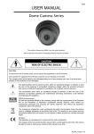
TT46
HYDRAULIC
TIE TAMPER
Safety, Operation and Maintenance
USER MANUAL
© 2012 Stanley Black & Decker, Inc.
New Britain, CT 06053
U.S.A.
60685 9-2013 Ver-8
DECLARATION OF CONFORMITY
DECLARATION OF CONFORMITY
ÜBEREINSTIMMUNGS-ERKLARUNG
DECLARATION DE CONFORMITE CEE
DECLARACION DE CONFORMIDAD
DICHIARAZIONE DI CONFORMITA
Hydraulic Tools
______________________________________________________________________
I, the undersigned:
Ich, der Unterzeichnende:
Je soussigné:
El abajo firmante:
lo sottoscritto:
Weisbeck, Andy
Surname and First names/Familiennname und Vornamen/Nom et prénom/Nombre y apellido/Cognome e nome
hereby declare that the equipment specified hereunder:
bestätige hiermit, daß erklaren Produkt genannten Werk oder Gerät:
déclare que l’équipement visé ci-dessous:
Por la presente declaro que el equipo se especifica a continuación:
Dichiaro che le apparecchiature specificate di seguito:
1.
Category:
Kategorie:
Catégorie:
Categoria:
Categoria:
Tie Tamper, Hydraulic
2.
Make/Marke/Marque/Marca/Marca
Stanley
3.
Type/Typ/Type/Tipo/Tipo:
TT46133
4.
Serial number of equipment:
Seriennummer des Geräts:
Numéro de série de l’équipement:
Numero de serie del equipo:
Matricola dell´attrezzatura:
All
Has been manufactured in conformity with
Wurde hergestellt in Übereinstimmung mit
Est fabriqué conformément
Ha sido fabricado de acuerdo con
E’ stata costruita in conformitá con
Directive/Standards
Richtlinie/Standards
Directives/Normes
Directriz/Los Normas
Direttiva/Norme
No.
Nr
Numéro
No
n.
Approved body
Prüfung durch
Organisme agréé
Aprobado
Collaudato
Machinery Directive
EN ISO
EN
2006/42/EC:2006
3744:2009
792-4:1996
Self
Self
Self
5.
Special Provisions:
None
Spezielle Bestimmungen:
Dispositions particulières:
Provisiones especiales:
Disposizioni speciali:
6.
Representative in the Union: Patrick Vervier, Stanley Dubuis 17-19, rue Jules Berthonneau-BP 3406 41034 Blois Cedex, France.
Vertreter in der Union/Représentant dans l’union/Representante en la Union/Rappresentante presso l’Unione
Sound Power Level: 107 dBA
Vibration Level: 6.3 m/s°
Done at/Ort/Fait à/Dado en/Fatto a Stanley Hydraulic Tools, Milwaukie, Oregon USA
Signature/Unterschrift/Signature/Firma/Firma
Position/Position/Fonction/Cargo/Posizione
9/4/2013
2 ► TT46 User Manual
Engineering Manager
Date/Datum/le/Fecha/Data
1-10-11
TABLE OF CONTENTS
DECLARATION OF CONFORMITY...........................................................................................................................2
SAFETY SYMBOLS....................................................................................................................................................4
SAFETY PRECAUTIONS...........................................................................................................................................5
TOOL STICKERS & TAGS.........................................................................................................................................6
TOOL HOSE INFORMATION .................................................................................................................................7-8
HTMA REQUIREMENTS............................................................................................................................................9
OPERATION.............................................................................................................................................................10
PREOPERATION PROCEDURES........................................................................................................................10
TOOL OPERATION ..............................................................................................................................................10
COLD WEATHER OPERATION............................................................................................................................10
EQUIPMENT PROTECTION & CARE...................................................................................................................... 11
TROUBLESHOOTING..............................................................................................................................................12
CHARGING THE ACCUMULATOR.....................................................................................................................13-14
SPECIFICATIONS....................................................................................................................................................15
ACCESSORIES........................................................................................................................................................15
SERVICE TOOLS.....................................................................................................................................................15
SOUND POWER AND VIBRATION DECLARATION...............................................................................................15
TT46113 & TT46133 ILLUSTRATION......................................................................................................................16
TT46113 & TT46133 PARTS LIST............................................................................................................................17
TT46112/TT4611204 ILLUSTRATION......................................................................................................................18
TT46112/TT4611204 PARTS LIST...........................................................................................................................19
IMPORTANT
To fill out a Product Warranty Recording form, and for information on your warranty,
visit Stanleyhydraulic.com and select the Warranty tab.
(NOTE: The warranty recording form must be submitted to validate the warranty).
SERVICING: This manual contains safety, operation, and routine maintenance instructions. Stanley Hydraulic Tools
recommends that servicing of hydraulic tools, other than routine maintenance, must be performed by an authorized
and certified dealer. Please read the following warning.
WARNING
SERIOUS INJURY OR DEATH COULD RESULT FROM THE IMPROPER REPAIR OR
SERVICE OF THIS TOOL.
REPAIRS AND / OR SERVICE TO THIS TOOL MUST ONLY BE DONE BY AN
AUTHORIZED AND CERTIFIED DEALER.
For the nearest authorized and certified dealer, call Stanley Hydraulic Tools at the number listed on the back of this
manual and ask for a Customer Service Representative.
TT46 User Manual ◄ 3
SAFETY SYMBOLS
Safety symbols and signal words, as shown below, are used to emphasize all operator, maintenance and repair actions which, if not strictly followed, could result in a life-threatening situation, bodily injury or damage to equipment.
This is the safety alert symbol. It is used to alert you to potential personal injury
hazards. Obey all safety messages that follow this symbol to avoid possible
injury or death.
DANGER
This safety alert and signal word indicate an imminently hazardous situation
which, if not avoided, will result in death or serious injury.
WARNING
This safety alert and signal word indicate a potentially hazardous situation
which, if not avoided, could result in death or serious injury.
CAUTION
This safety alert and signal word indicate a potentially hazardous situation
which, if not avoided, could result in death or serious injury.
CAUTION
This signal word indicates a potentially hazardous situation which, if not avoided, may result in property damage.
NOTICE
This signal word indicates a situation which, if not avoided, will result in damage
to the equipment.
IMPORTANT
This signal word indicates a situation which, if not avoided, may result in damage to the equipment.
Always observe safety symbols. They are included for your safety and for the protection of the tool.
LOCAL SAFETY REGULATIONS
Enter any local safety regulations here. Keep these instructions in an area accessible to the operator and maintenance personnel.
4 ► TT46 User Manual
SAFETY PRECAUTIONS
Tool operators and maintenance personnel must always comply
with the safety precautions given in this manual and on the stickers and tags attached to the tool and hose.
These safety precautions are given for your safety. Review them
carefully before operating the tool and before performing general
maintenance or repairs.
Supervising personnel should develop additional precautions relating to the specific work area and local safety regulations. If so,
place the added precautions in the space provided on page 5.
The tool will provide safe and dependable service if operated in
accordance with the instructions given in this manual. Read and
understand this manual and any stickers and tags attached to the
tool and hose before operation. Failure to do so could result in
personal injury or equipment damage.
• The operator must start in a work area without bystanders. Flying debris can cause serious injury.
• Do not operate the tool unless thoroughly trained or under the
supervision of an instructor. Establish a training program for all
operators to ensure safe operation.
• Always wear safety equipment such as goggles, ear and head
protection, and safety shoes at all times when operating the tool.
Use gloves and aprons when necessary.
• The operator must be familiar with all prohibited work areas such
as excessive slopes and dangerous terrain conditions.
• Never wear loose clothing that can get entangled in the working parts of the tool.
• Keep all parts of your body away from the moving parts. Long
hair or loose clothing can become drawn into moving components.
• Do not weld, cut with an acetylene torch or hardface the tie
tamper tool. Do not operate a damaged, improperly adjusted,
or incompletely assembled tool.
• Always use accessories that conform to the specifications
given in the OPERATION section of this manual.
• Release the trigger if the power supply has been interrupted.
• When working near electrical conductors, always assume that
all conductors are energized and that insulation, clothing and
hoses can conduct electricity. Use hose labeled and certified as
non-conductive.
• To avoid personal injury or equipment damage, all tool repair,
maintenance and service must only be performed by authorized
and properly trained personnel.
• Do not carry the tool by hoses.
• Warning: Use of this tool on certain materials during demolition could generate dust potentially containing a variety of hazardous substances such as asbestos, silica or lead. Inhalation
of dust containing these or other hazardous substances could
result in serious injury, cancer or death. Protect yourself and
those around you. Research and understand the materials you
are cutting. Follow correct safety procedures and comply with
all applicable national, state or provisional health and safety
regulations relating to them, including, if appropriate arranging
for the safe disposal of the materials by a qualified person.
• Maintain proper footing and balance at all times.
• Do not inspect or clean the tool while the hydraulic power source
is connected. Accidental engagement of the tool can cause serious injury.
• Always connect hoses to the tool hose couplers before energizing the hydraulic power source. Be sure all hose
connections are tight and are in good condition.
• Do not operate the tool at oil temperatures above 140°F/60°C.
Operation at higher temperatures can cause higher than normal
temperatures at the tool which can result in operator discomfort.
• Do not operate a damaged, improperly adjusted, or incompletely
assembled tie tamper.
TT46 User Manual ◄ 5
TOOL STICKERS & TAGS
28322
CE STICKER (CE)
25610
RAILROAD HELP DESK STICKER
Lwa
28409
COMPOSITE STICKER
107
11206
CIRCUIT TYPE C STICKER (CE)
17784
SOUND POWER STICKER
07589
CAUTION/GPM STICKER
23230
NAME TAG (4-6 GPM MODELS)
65049
NAME TAG (10 GPM MODEL)
NOTE:
THE INFORMATION LISTED
ON THE STICKERS SHOWN,
MUST BE LEGIBLE AT ALL
TIMES.
REPLACE DECALS IF
THEY BECOME WORN OR
DAMAGED. REPLACEMENTS
ARE AVAILABLE FROM
YOUR LOCAL STANLEY
DISTRIBUTOR.
The safety tag (P/N 15875) at right is
attached to the tool when shipped from
the factory. Read and understand the
safety instructions listed on this tag before
removal. We suggest you retain this tag and
attach it to the tool when not in use.
D A N G E R
1.
FAILURE TO USE HYDRAULIC HOSE LABELED AND CERTIFIED AS NON-CONDUCTIVE WHEN USING HYDRAULIC
TOOLS ON OR NEAR ELECTRICAL LINES MAY RESULT IN
DEATH OR SERIOUS INJURY.
BEFORE USING HOSE LABELED AND CERTIFIED AS NONCONDUCTIVE ON OR NEAR ELECTRIC LINES BE SURE THE
HOSE IS MAINTAINED AS NON-CONDUCTIVE. THE HOSE
SHOULD BE REGULARLY TESTED FOR ELECTRIC CURRENT LEAKAGE IN ACCORDANCE WITH YOUR SAFETY
DEPARTMENT INSTRUCTIONS.
2.
A HYDRAULIC LEAK OR BURST MAY CAUSE OIL INJECTION INTO THE BODY OR CAUSE OTHER SEVERE
PERSONAL INJURY.
A.
DO NOT EXCEED SPECIFIED FLOW AND PRESSURE
FOR THIS TOOL. EXCESS FLOW OR PRESSURE MAY
CAUSE A LEAK OR BURST.
B.
DO NOT EXCEED RATED WORKING PRESSURE OF
HYDRAULIC HOSE USED WITH THIS TOOL. EXCESS
PRESSURE MAY CAUSE A LEAK OR BURST.
C.
CHECK TOOL HOSE COUPLERS AND CONNECTORS
DAILY FOR LEAKS. DO NOT FEEL FOR LEAKS WITH
YOUR HANDS. CONTACT WITH A LEAK MAY RESULT
IN SEVERE PERSONAL INJURY.
D A N G E R
D.
DO NOT LIFT OR CARRY TOOL BY THE HOSES. DO
NOT ABUSE HOSE. DO NOT USE KINKED, TORN OR
DAMAGED HOSE.
3.
MAKE SURE HYDRAULIC HOSES ARE PROPERLY CONNECTED TO THE TOOL BEFORE PRESSURING SYSTEM.
SYSTEM PRESSURE HOSE MUST ALWAYS BE CONNECTED TO TOOL “IN” PORT. SYSTEM RETURN HOSE
MUST ALWAYS BE CONNECTED TO TOOL “OUT” PORT.
REVERSING CONNECTIONS MAY CAUSE REVERSE
TOOL OPERATION WHICH CAN RESULT IN SEVERE
PERSONAL INJURY.
4.
DO NOT CONNECT OPEN-CENTER TOOLS TO CLOSEDCENTER HYDRAULIC SYSTEMS. THIS MAY RESULT IN
LOSS OF OTHER HYDRAULIC FUNCTIONS POWERED BY
THE SAME SYSTEM AND/OR SEVERE PERSONAL INJURY.
5.
BYSTANDERS MAY BE INJURED IN YOUR WORK AREA.
KEEP BYSTANDERS CLEAR OF YOUR WORK AREA.
6.
WEAR HEARING, EYE, FOOT, HAND AND HEAD PROTECTION.
7.
TO AVOID PERSONAL INJURY OR EQUIPMENT DAMAGE,
ALL TOOL REPAIR MAINTENANCE AND SERVICE MUST
ONLY BE PERFORMED BY AUTHORIZED AND PROPERLY
TRAINED PERSONNEL.
I M P O R T A N T
I M P O R T A N T
READ OPERATION MANUAL AND
SAFETY INSTRUCTIONS FOR THIS
TOOL BEFORE USING IT.
READ OPERATION MANUAL AND
SAFETY INSTRUCTIONS FOR THIS
TOOL BEFORE USING IT.
USE ONLY PARTS AND REPAIR
PROCEDURES APPROVED BY
STANLEY AND DESCRIBED IN THE
OPERATION MANUAL.
USE ONLY PARTS AND REPAIR
PROCEDURES APPROVED BY
STANLEY AND DESCRIBED IN THE
OPERATION MANUAL.
TAG TO BE REMOVED ONLY BY
TOOL OPERATOR.
TAG TO BE REMOVED ONLY BY
TOOL OPERATOR.
SEE OTHER SIDE
SEE OTHER SIDE
SAFETY TAG P/N 15875 (Shown smaller then actual size)
6 ► TT46 User Manual
HOSE TYPES
The rated working pressure of the hydraulic hose must be equal to or higher than the relief valve setting on the hydraulic system. There are three types of hydraulic hose that meet this requirement and are authorized for use with
Stanley Hydraulic Tools. They are:
Certified non-conductive — constructed of thermoplastic or synthetic rubber inner tube, synthetic fiber braid
reinforcement, and weather resistant thermoplastic or synthetic rubber cover. Hose labeled certified nonconductive is the only hose authorized for use near electrical conductors.
Wire-braided (conductive) — constructed of synthetic rubber inner tube, single or double wire braid reinforcement, and weather resistant synthetic rubber cover. This hose is conductive and must never be used near
electrical conductors.
Fabric-braided (not certified or labeled non-conductive) — constructed of thermoplastic or synthetic rubber inner tube, synthetic fiber braid reinforcement, and weather resistant thermoplastic or synthetic rubber cover. This
hose is not certified non-conductive and must never be used near electrical conductors.
HOSE SAFETY TAGS
To help ensure your safety, the following DANGER tags are attached to all hose purchased from Stanley Hydraulic
Tools. DO NOT REMOVE THESE TAGS.
If the information on a tag is illegible because of wear or damage, replace the tag immediately. A new tag may be
obtained from your Stanley Distributor.
D A N G E R
D A N G E R
1.
FAILURE TO USE HYDRAULIC HOSE LABELED AND CERTIFIED AS NON-CONDUCTIVE
WHEN USING HYDRAULIC TOOLS ON OR NEAR ELECTRIC LINES MAY RESULT IN
DEATH OR SERIOUS INJURY.
FOR PROPER AND SAFE OPERATION MAKE SURE THAT YOU HAVE BEEN PROPERLY TRAINED IN CORRECT PROCEDURES REQUIRED FOR WORK ON OR AROUND
ELECTRIC LINES.
2.
BEFORE USING HYDRAULIC HOSE LABELED AND CERTIFIED AS NON-CONDUCTIVE
ON OR NEAR ELECTRIC LINES. WIPE THE ENTIRE LENGTH OF THE HOSE AND FITTING WITH A CLEAN DRY ABSORBENT CLOTH TO REMOVE DIRT AND MOISTURE AND
TEST HOSE FOR MAXIMUM ALLOWABLE CURRENT LEAKAGE IN ACCORDANCE WITH
SAFETY DEPARTMENT INSTRUCTIONS.
3.
DO NOT EXCEED HOSE WORKING PRESSURE OR ABUSE HOSE. IMPROPER USE
OR HANDLING OF HOSE COULD RESULT IN BURST OR OTHER HOSE FAILURE.
KEEP HOSE AS FAR AWAY AS POSSIBLE FROM BODY AND DO NOT PERMIT DIRECT
CONTACT DURING USE. CONTACT AT THE BURST CAN CAUSE BODILY INJECTION
AND SEVERE PERSONAL INJURY.
4.
HANDLE AND ROUTE HOSE CAREFULLY TO AVOID KINKING, ABRASION, CUTTING, OR
CONTACT WITH HIGH TEMPERATURE SURFACES. DO NOT USE IF KINKED. DO NOT
USE HOSE TO PULL OR LIFT TOOLS, POWER UNITS, ETC.
5.
CHECK ENTIRE HOSE FOR CUTS CRACKS LEAKS ABRASIONS, BULGES, OR DAMAGE TO COUPLINGS IF ANY OF THESE CONDITIONS EXIST, REPLACE THE HOSE
IMMEDIATELY. NEVER USE TAPE OR ANY DEVICE TO ATTEMPT TO MEND THE HOSE.
6.
AFTER EACH USE STORE IN A CLEAN DRY AREA.
SEE OTHER SIDE
SIDE 1
SEE OTHER SIDE
(Shown smaller than actual size)
DO NOT REMOVE THIS TAG
DO NOT REMOVE THIS TAG
THE TAG SHOWN BELOW IS ATTACHED TO “CERTIFIED NON-CONDUCTIVE” HOSE
SIDE 2
D A N G E R
D A N G E R
1.
DO NOT USE THIS HYDRAULIC HOSE ON OR NEAR ELECTRIC LINES. THIS HOSE IS
NOT LABELED OR CERTIFIED AS NON-CONDUCTIVE. USING THIS HOSE ON OR NEAR
ELECTRICAL LINES MAY RESULT IN DEATH OR SERIOUS INJURY.
5.
CHECK ENTIRE HOSE FOR CUTS CRACKS LEAKS ABRASIONS, BULGES, OR DAMAGE TO
COUPLINGS IF ANY OF THESE CONDITIONS EXIST, REPLACE THE HOSE IMMEDIATELY.
NEVER USE TAPE OR ANY DEVICE TO ATTEMPT TO MEND THE HOSE.
2.
FOR PROPER AND SAFE OPERATION MAKE SURE THAT YOU HAVE BEEN PROPERLY
TRAINED IN CORRECT PROCEDURES REQUIRED FOR WORK ON OR AROUND ELECTRIC LINES.
6.
AFTER EACH USE STORE IN A CLEAN DRY AREA.
3.
DO NOT EXCEED HOSE WORKING PRESSURE OR ABUSE HOSE. IMPROPER USE OR
HANDLING OF HOSE COULD RESULT IN BURST OR OTHER HOSE FAILURE. KEEP HOSE
AS FAR AWAY AS POSSIBLE FROM BODY AND DO NOT PERMIT DIRECT CONTACT
DURING USE. CONTACT AT THE BURST CAN CAUSE BODILY INJECTION AND SEVERE
PERSONAL INJURY.
4.
HANDLE AND ROUTE HOSE CAREFULLY TO AVOID KINKING, CUTTING, OR CONTACT
WITH HIGH TEMPERATURE SURFACES. DO NOT USE IF KINKED. DO NOT USE HOSE TO
PULL OR LIFT TOOLS, POWER UNITS, ETC.
DO NOT REMOVE THIS TAG
DO NOT REMOVE THIS TAG
THE TAG SHOWN BELOW IS ATTACHED TO “CONDUCTIVE” HOSE.
SEE OTHER SIDE
SEE OTHER SIDE
SIDE 1
SIDE 2
(Shown smaller than actual size)
TT46 User Manual ◄ 7
8 ► TT46 User Manual
All hydraulic hose must meet or exceed
specifications as set forth by SAE J517.
All hydraulic hose must have at least a rated
minimum working pressure equal to the maximum hydraulic system relief valve setting.
This chart is intended to be used for hydraulic
tool applications only based on Stanley Hydraulic Tools tool operating requirements and
should not be used for any other applications.
The chart to the right shows recommended
minimum hose diameters for various hose
lengths based on gallons per minute (gpm)/
liters per minute (lpm). These recommendations are intended to keep return line pressure
(back pressure) to a minimum acceptable level to ensure maximum tool performance.
Tool to Hydraulic Circuit Hose
Recommendations
15-34
MM
Inside Diameter
INCH
USE
(Press/Return)
PSI
up to 10
up to 3
3/8
10
Both
2250
49-60
13-16
FLOW >>>
RETURN
<<< FLOW
PRESSURE
26-100
up to 25
100-200
51-100
up to 50
100-300
51-100
up to 50
26-100
up to 25
8-30
up to 8
30-60
15-30
up to 15
30-90
15-30
up to 15
7.5-30
up to 7.5
Figure 1. Typical Hose Connections
49-60
38-49
10-13
13-16
19-40
5-10.5
38-49
19-40
5-10.5
10-13
19-40
5-10.5
38-49
15-23
10-13
15-23
4-6
19
25.4
16
19
19
25.4
5/8
3/4
3/4
1
19
3/4
1
16
3/4
16
19
3/4
5/8
16
5/8
5/8
16
13
13
10
5/8
1/2
1/2
3/8
Return
Pressure
Return
Pressure
Return
Pressure
Return
Pressure
Both
Return
Pressure
Both
Both
Both
Both
2500
2500
2500
2500
2500
2500
2500
2500
2500
2500
2500
2500
2500
2500
2500
175
175
175
175
175
175
175
175
175
175
175
175
175
175
175
155
BAR
Min. Working Pressure
Certified Non-Conductive Hose - Fiber Braid - for Utility Bucket Trucks
METERS
Hose Lengths
FEET
Conductive Hose - Wire Braid or Fiber Braid -DO NOT USE NEAR ELECTRICAL CONDUCTORS
4-6
4-9
LPM
Oil Flow
GPM
HOSE RECOMMENDATIONS
HTMA / EHTMA REQUIREMENTS
HTMA / EHTMA REQUIREMENTS
HTMA
HYDRAULIC SYSTEM REQUIREMENTS
TYPE I
Nominal Operating Pressure
(at the power supply outlet)
4-6 gpm
(15-23 lpm)
1500 psi
(103 bar)
TOOL TYPE
TYPE II
TYPE RR
7-9 gpm
(26-34 lpm)
1500 psi
(103 bar)
9-10.5 gpm
(34-40 lpm)
1500 psi
(103 bar)
System relief valve setting
(at the power supply outlet)
2100-2250 psi
(145-155 bar)
2100-2250 psi
(145-155 bar)
2200-2300 psi
(152-159 bar)
2100-2250 psi
(145-155 bar)
Maximum back pressure
(at tool end of the return hose)
250 psi
(17 bar)
250 psi
(17 bar)
250 psi
(17 bar)
250 psi
(17 bar)
Measured at a max. fluid viscosity of:
(at min. operating temperature)
400 ssu*
400 ssu*
400 ssu*
400 ssu*
(82 centistokes) (82 centistokes) (82 centistokes) (82 centistokes)
Temperature: Sufficient heat rejection
capacity to limit max. fluid temperature to:
(at max. expected ambient temperature)
140° F
(60° C)
Flow Range
140° F
(60° C)
140° F
(60° C)
TYPE III
11-13 gpm
(42-49 lpm)
1500 psi
(103 bar)
140° F
(60° C)
3 hp
5 hp
6 hp
7 hp
Min. cooling capacity at a temperature
(2.24 kW)
(3.73 kW)
(5.22 kW)
(4.47 kW)
difference of between ambient and fluid
40° F
40° F
40° F
40° F
temps
(22° C)
(22° C)
(22° C)
(22° C)
NOTE:
Do not operate the tool at oil temperatures above 140° F (60° C). Operation at higher temperatures can cause operator
discomfort at the tool.
Filter
Min. full-flow filtration
Sized for flow of at least:
(For cold temp. startup and max.
dirt-holding capacity)
25 microns
30 gpm
(114 lpm)
Hydraulic fluid Petroleum based
(premium grade, anti-wear, non-conductive)
Viscosity (at min. and max. operating temps)
100-400 ssu*
25 microns
30 gpm
(114 lpm)
25 microns
30 gpm
(114 lpm)
100-400 ssu*
100-400 ssu*
(20-82 centistokes)
25 microns
30 gpm
(114 lpm)
100-400 ssu*
NOTE:
When choosing hydraulic fluid, the expected oil temperature extremes that will be experienced in service determine the
most suitable temperature viscosity characteristics. Hydraulic fluids with a viscosity index over 140 will meet the requirements
over a wide range of operating temperatures.
*SSU = Saybolt Seconds Universal
EHTMA
HYDRAULIC SYSTEM
REQUIREMENTS
CLASSIFICATION
B
C
D
Nominal Operating Pressure
(at the power supply outlet)
3.5-4.3 gpm
(13.5-16.5 lpm)
1870 psi
(129 bar)
4.7-5.8 gpm
(18-22 lpm)
1500 psi
(103 bar)
7.1-8.7 gpm
(27-33 lpm)
1500 psi
(103 bar)
9.5-11.6 gpm
(36-44 lpm)
1500 psi
(103 bar)
11.8-14.5 gpm
(45-55 lpm)
1500 psi
(103 bar)
System relief valve setting
(at the power supply outlet)
2495 psi
(172 bar)
2000 psi
(138 bar)
2000 psi
(138 bar)
2000 psi
(138 bar)
2000 psi
(138 bar)
Flow Range
NOTE: These are general hydraulic system requirements. See tool specification page for tool specific requirements
TT46 User Manual ◄ 9
OPERATION
PREOPERATION PROCEDURES
making connections.
CHECK HYDRAULIC POWER SOURCE
2. Connect the hoses from the hydraulic power source to
the tool fitting or quick disconnects. It is a good practice to
connect the return hose first and disconnect it last to minimize or avoid trapped pressure within the tool.
1. Using a calibrated flowmeter and pressure gauge, check
that the hydraulic power source develops a flow of 4-6
gpm/15-23 lpm at 1500-2000 psi/106-140 bar. For TT46233
Model, 7-10 gpm/26-38 lpm.
2. Make certain the hydraulic power source is equipped
with a relief valve set to open at 2200-2300 psi/152-159 bar
minimum. Maximum full flow pressure not to exceed 2500
psi/172 bar.
INSTALL TOOL BIT
1. Remove the two capscrews that hold the bit keeper to
the lower body or on some models remove the two hex
head capscrews, outer springs, and nuts that hold the bit
keeper to the lower body.
2. Remove the two pair of bit-retaining spring guides and
spring or on some models the one pair of bit guides from
the bit keeper.
3. Insert the hex end of the bit as far as possible through
the small end of the bit keeper (see parts list illustration).
3. If hose couplers are used, observe flow indicators
stamped on hose couplers to be sure that oil will flow in the
proper direction. The female coupler is the inlet (pressure)
coupler.
NOTE:
The pressure increase in uncoupled hoses left in the
sun may result in making them difficult to connect.
When possible, connect the free ends of operating
hoses together.
TOOL OPERATION
1. Observe all safety precautions.
2. Install the appropriate tool bit for the job if not already
installed.
3. Place the tamper on the surface to be compacted.
WARNING
4. Install the coil spring on the bit hex flange. Install a
spring guide pair on each end of the spring. On some models only the one pair of bit guides need to be installed and
no spring.
The Tamper will rise quickly when first turned on. Do not
stand over or place any part of your body on top of the
tamper. Wear safety shoes.
Note: There are two types of spring guides. Each of the
two types must be installed in matched pairs. The pair used
at the top of the spring have a flat end that goes against the
bit collar.
Note:
Partially pressing the trigger allows the tool to run at
slow speed, making it easier to start or control.
Carefully install the bit keeper so that the lower spring
guide fits into the lower keeper bore and that the upper flat
end of the guide rests against the bit flange.
5. Guide the tamper using both hands.
COLD WEATHER OPERATION
5. With the bit pulled down into the keeper, insert into the
tie tamper hex, then press the bit keeper up against the
lower body.
If the tie tamper is to be used during cold weather, preheat
the system hydraulic fluid at low engine speed.
6. Tighten both capscrews or on some models install the
hex head capscrews, outer springs, and nuts and tighten
securely.
When using the normally recommended fluids, oil fluid
temperature should be at or above 50° F/10° C (400 ssu/82
centistokes) before use.
CONNECT HOSES
Damage to the hydraulic system or tie tamper can result
from use with oil that is too viscous or thick.
1. Wipe all hose couplers with a clean lint-free cloth before
10 ► TT46 User Manual
TOOL PROTECTION & CARE
NOTICE
In addition to the Safety Precautions found in
this manual, observe the following for equipment
protection and care.
• Make sure all couplers are wiped clean before connection.
• The hydraulic circuit control valve must be in the “OFF” position when coupling or uncoupling
hydraulic tools. Failure to do so may result in damage to the quick couplers and cause overheating
of the hydraulic system.
• Always store the tool in a clean dry space, safe from damage or pilferage.
• Make sure the circuit PRESSURE hose (with male quick disconnect) is connected to the “IN” port.
The circuit RETURN hose (with female quick disconnect) is connected to the opposite port. Do not
reverse circuit flow. This can cause damage to internal seals.
• Always replace hoses, couplings and other parts with replacement parts recommended by Stanley
Hydraulic Tools. Supply hoses must have a minimum working pressure rating of 2500 psi/172 bar.
• Do not exceed the rated flow (see Specifications) in this manual for correct flow rate and
model number. Rapid failure of the internal seals may result.
• Always keep critical tool markings, such as warning stickers and tags legible.
• Tool repair should be performed by experienced personnel only.
• Make certain that the recommended relief valves are installed in the pressure side of the system.
• Do not use the tool for applications for which it was not intended.
TT46 User Manual ◄ 11
TROUBLESHOOTING
If symptoms of poor performance develop, the following chart can be used as a guide to correct the problem. When diagnosing faults in operation of the wrench, always check that the hydraulic power source is supplying the correct hydraulic
flow and pressure to the tool as listed in the following table. Use a flow meter known to be accurate. Check the flow with
the hydraulic fluid temperature at least 80o F/27o C.
SYMPTOM
CAUSE
SOLUTION
Tie tamper does not run.
Power unit not functioning.
Check power source for proper flow
and pressure, 4-6 gpm/14-23 lpm,
1500-2000 psi/106-140 bar. TT46233
Model, 7-10 gpm/26-38 lpm.
Couplers or hoses blocked.
Remove restriction.
Pressure and return line hoses reversed at ports.
Be sure hoses are connected to their
proper ports.
Mechanical failure of piston or automatic valve.
Disassemble tamper and inspect for
damaged parts.
Power unit not functioning.
Check power source for proper flow
and pressure, 4-6 gpm/14-23 lpm,
1500-2000 psi/106-140 bar. TT46233
Model, 7-10 gpm/26-38 lpm.
Couplers or hoses blocked.
Remove restriction.
Low accumulator charge (pressure
hoses will pulse more than normal).
Recharge accumulator. Replace diaphragm if charge loss continues.
Oil too hot (above 140°F/60°C).
Provide cooler to maintain proper oil
temperature (140°F/60°C).
Low gpm supply from power unit.
Check power source for proper flow
and pressure, 4-6 gpm/14-23 lpm,
1500-2000 psi/106-140 bar. TT46233
Model, 7-10 gpm/26-38 lpm.
High back-pressure.
Check hydraulic system for excessive
back-pressure (over 200 psi/14 bar).
Tie Tamper does not run effectively.
Tie Tamper operates slow.
12 ► TT46 User Manual
CHARGING THE ACCUMULATOR
CHARGING THE ACCUMULATOR
To check or charge the accumulator the following equipment is required:
• Accumulator tester (Part Number 02835).
• Charging assembly (Part Number 15304)
(includes a guage w/snub valve, hose and fitting).
• NITROGEN bottle with a 800 psi/56 bar minimum charge.
1. On charge valves containing 5/8 inch hex locking nuts,
first loosen the locking nut 1-1/2 turns.
2. Holding the chuck end of the Stanley tester (p/n 02835),
turn the gauge fully counterclockwise to ensure the stem
inside the chuck is completely retracted.
3. Thread the tester onto the charging valve of the tool accumulator (do not advance the gauge-end into the chuck
end. Turn as a unit). Seat the chuck on the accumulator
charging valve and hand tighten only.
4. Advance the valve stem by turning the gauge- end clockwise.
5. Connect the charge fitting on the hose to the charge
valve on the 02835 Tester.
6. With the gauge and snub valve attached to the nitrogen
bottle, and with the snub valve closed, open the nitrogen
bottle valve.
NOTE:
It may be necessary to adjust the charge at 650-700
psi/45-48 bar to overcome any pressure drop through
the charging system.
7. While watching the pressure gage open the snub valve
allowing the gauge to read 600 to 700 psi/42 to 48 bar,
close the snub valve on the charging assembly and also
on the nitrogen bottle, remove the charging assembly from
the accumulator tester.
8. Turn the gauge end of the tester fully counterclockwise
to retract the plunger in the chuck. Then remove the tester
from the charge valve.
9.On charge valves containing 5/8 inch hex locking nuts,
tighten the locking nut.
TESTING THE ACCUMULATOR
PRESSURE
1. Follow instructions 1 through 4 under "CHARGING THE
ACCUMULATOR".
2. Read the pressure on the gauge (pressure should be
between 500 & 600 psi/35 & 42 bar.
3. If the pressure is low, recharge the tool.
TT46 User Manual ◄ 13
CHARGING THE ACCUMULATOR
Charge Location
TT46113, TT46113C,
TT46133,
TT46133B,
TT46133C, TT46133UP
Charging
theonAccumulator
(BR
45 with
Anti-Vibration
Handles)and TT46233
CW
TESTER CHARGING
VALVE
CHUCK
GAUGE
LOCATION OF CHARGING VALVE
ACCUMULATOR TESTER ( P/N 02835 )
Figure 2
Liquid Filled Gauge w/Snub Valve
Charge Fitting
Nitrogen Tank
(Not included in Kit)
Charging Valve
31254 ACCUMULATOR CHARGE KIT
Includes: Liquid Filled Gauge w/Snub Valve,
Hose, Charge Fitting, 02835 Tester, and Box
(not pictured)
Hose
Gauge
02835 TESTER
Chuck
Charge Location
TT4611204 and TT4611206
Charging
theonAccumulator
(BR45 with T-Handles)
CW
TESTER CHARGING
VALVE
CHUCK
GAUGE
LOCATION OF CHARGING VALVE
ACCUMULATOR TESTER ( P/N 02835 )
14 ► TT46 User Manual
Figure 2
SPECIFICATIONS
SPECIFICATIONS
Pressure Range........................................................................................................................1500-2000 psi /106-140 bar
Maximum Back Pressure............................................................................................................................. 200 psi / 14 bar
Flow Range ..........................................................................................................................................4-6 gpm / 15-23 lpm
Optimum Flow................................................................................................................................................. 5 gpm/20 lpm
Porting ............................................................................................................................................................-8 SAE O-ring
Connect Size and Type .......................................................................................................... 3/8 in. Male Pipe Hose Ends
Connector..................................................................................................................................HTMA Flush Faced Coupler
Hose Whips..................................................................................................................................................................... Yes
System Type.............................................................................................EHTMA Category C/HTMA Type I - Open Center
Weight (Rigid "T" Handle model w/Steel) ......................................................................................................... 54 lb / 24 kg
(Anti-Vibration model w/Steel)................................................................................................................ 56 lb / 25 kg
Overall Length (Rigid "T" Handle model w/Steel)............................................................................. 38.75 inches / 98.4 cm
(Antivibration model w/Steel).................................................................................................39.75 inches / 100.9 cm
Overall Width (Rigid/Anti-Vibr. models) .......................................................................................14/17 inches / 35.6/44 cm
SOUND POWER AND VIBRATION DECLARATION
Test conducted on BR4056801 (same as TT46),operated at standard 5 gpm input....................................................
Measured A-weighted sound power level, Lwa (ref. 1pW) in decibels........................................................... 106 dBA
Uncertainty, Kwa, in decibels.............................................................................................................................. 3 dBA
Guaranteed sound power level...................................................................................................................... 109 dBA
Measured A-weighted sound pressure level, Lpa (ref. 20 µPa) at operator's position, in decibels.................. 98 dBA
Uncertainty, Kpa, in decibels.............................................................................................................................. 3 dBA
Values determined according to noise test code given in ISO 15744, using the basic standard ISO374
4
Test conducted by independent notified body to comply with 2000/14/EC:2005
requirements.
NOTE- The sum of a measured noise emission value and
its associated uncertainty represents an upper boundary of the range of values which is likely to occur in measurements............................................................................................................................................................................
Declared vibration emission value in accordance with EN 12096................................................................................
Measured vibration emission value: 3-Axis................................................................................................. 6.3 m/sec²
Uncertainty: K................................................................................................................................................. 1 m/sec²
Measured vibration emission value: Z-Axis.................................................................................................... 3 m/sec²
Uncertainty: K.............................................................................................................................................. 0.7 m/sec²
Values determined according to ISO 8662-5, ISO 5349-1,2........................................................................................
ACCESSORIES
Tie Tamper Steel 4 inch w/"V" Cut (18 inch OAL)........................................................................................................44979
Tie TAmper Steel 4 inch w/”V” Cut (18 inch OAL) Heavy Duty....................................................................................59034
Tie Tamper Steel 4 inch w/"V" Cut (21 inch OAL)........................................................................................................44937
Tie Tamper Steel 4 inch w/”V” Cut (21 inch OAL) Heavy Duty....................................................................................59033
Tie Tamper Steel 4 inch (24 inch OAL)........................................................................................................................33200
Pre-assembled Anti-Vibration Handle Conversion Kit.................................................................................................27680
SERVICE TOOLS
Tamping Sleeve Tool.................................................................................................................................................. 01120
O-Ring Tool Kit........................................................................................................................................................... 04337
Flow Sleeve Removal Tube........................................................................................................................................ 04910
Flow Sleeve Removal Tool......................................................................................................................................... 04919
Accumulator Cylinder Puller....................................................................................................................................... 05640
TEST EQUIPMENT
Accumulator Tester..................................................................................................................................................... 02835
Accumulator Charge Kit (Includes Gauge w/Snub Valve, Hose, Charge Fitting, and Accumulator Tester................. 31254
Charging Assembly (Includes Gauge w/Snub Valve, Hose, and Charge Fitting)....................................................... 15304
Flow and Pressure Tester........................................................................................................................................... 04182
TT46 User Manual ◄ 15
TT46113/133/233 PARTS ILLUSTRATION
TT46113/TT46113C Use
Lower End Assy Shown
Below.
Illustration Covers Models:
TT46113
TT46113C
TT46133
TT46133B
TT46133C
TT46133 UP
TT46233
16 ► TT46 User Manual
TT46113/133/233 PARTS LIST
Item
1
2
3
4
5
6
7
8
9
10
11
12
13
14
15
16
17
18
19
20
21
22
23
24
25
26
27
28
29
30
31
32
33
34
35
36
37
38
39
40
41
42
Part No.
03972
47436
03973
47437
02900
56725
66727
12832
01605
04058
20515
04057
00293
01362
04056
07493
20499
02494
28369
20500
20511
28494
04374
20502
29045
20498
20505
20508
07479
12833
04385
17784
07589
28409
04605
11588
07485
04384
28322
11206
04381
04379
04378
07480
04380
23230
65049
04571
04382
12307
Qty
1
1
2
2
1
2
1
1
1
1
1
1
1
1
2
1
2
1
1
4
1
1
2
1
2
1
1
1
1
4
1
1
1
1
2
2
1
1
1
2
1
2
Description
Female Coupler (Parker)
Female Coupler (Aeroquip)
Male Coupler (Parker)
Male Coupler (Aeroquip)
Roll Pin
Hose Assy (Parker)
Hose Assy (Aeroquip)
Orifice Plug
O-Ring (Incl with Item 4)
Spring
Valve Spool
Bushing
O-Ring
O-Ring
Rod Wiper
Plug
Charge Valve
Handle Grip
Handle
Spirol Pin
Lever
Top Plate
Locknut
Trigger
Trigger Handle
Spring
Handle Pivot
Pivot Screw
Accumulator Diaphragm
Piston
Piston (TT46233 Only)
Sound Power Level Sticker (CE
Models Only)
GPM Sticker (TT46113,
TT4612303 Only)
Composite Sticker
Push Pin
Accumulator Charge Block
Flow Sleeve
Flow Sleeve (TT46233 Only)
CE Sticker
Circuit Type C Sticker (CE Only)
Backup Ring
O-Ring
Porting Block
Automatic Valve Body
Automatic Valve Body (TT46233
Only)
Name Tag
Name Tag (TT46233 Only)
Push Pin
Automatic Valve
Nut
Item
43
44
45
46
47
48
49
Part No.
12148
04383
25610
32258
32249
38008
44937
59033
Qty
2
1
1
1
Description
Spring
Flow Sleeve Tube
Railroad Help Desk Sticker
Bit Keeper
Bit Guide (Pair) Hex Shank
1
Bit Guide (Pair) Round Shank
(TT46133/133B/ 133C/133UP/
TT46233 Only)
Tie Tamper Bit
Tie Tamper Bit (TT46133/
TT46233 Only)
Hex Bushing
Lower Body
Lower Body (TT46233 Ony)
O-Ring
Rod Wiper
Washer
Cup Seal
Capscrew
Side Rod
Filler
Lower Body (TT46113/
TT46113C Only)
ESNA Nut (TT46113/TT46113C
Only)
Tie Tamper Steel (TT46113/
TT46113C Only)
Bit Retaining Top Spring (Guide
Pair) (TT46113/TT46113C Only)
Compression Coil Spring
(TT46113/TT46113C Only)
Bit Retaining Spring (Guide
Pair) (TT46113/TT46113C Only)
Bit Keeper Weldment (TT46113/
TT46113C Only)
Washer (TT46113/TT46113C
Only)
Capscrew (TT46113/TT46113C
Only)
1
1
51
52
53
54
55
56
57
15400
31955
65046
02022
04387
04780
04386
25304
20517
29959
58
23147
1
59
371500
2
60
44937
1
61
21028
1
62
21029
1
63
15411
1
64
22890
1
65
371050
2
66
15630
2
04595
1
50
1
1
1
1
1
2
4
1
SEAL KIT
Lower Body Assy Part No., 33037. Includes Items 49-50.
Tie Tamper Update Kit: Part No. 33038. Includes Items 4243, 46-47, 49-55
TT46 User Manual ◄ 17
TT46112 PARTS ILLUSTRATION
18 ► TT46 User Manual
TT46112 PARTS LIST
Item
1
2
3
4
5
6
7
8
9
10
11
12
13
14
15
16
17
18
19
20
21
22
23
24
25
26
27
28
29
30
31
32
33
34
35
36
37
38
39
40
41
42
43
Part No.
03972
47436
03973
47437
02900
56725
66727
12832
01605
04058
04077
04057
00293
01362
04056
07493
20499
02494
07483
07492
04374
04371
07479
12833
07589
11588
04605
07485
04381
04379
04378
07480
04571
04382
23230
25610
04383
04386
04780
04387
02022
23147
33037
04373
371500
15400
44937
44979
Qty
1
1
2
2
1
2
1
1
1
1
1
1
1
1
2
1
2
4
1
1
1
1
1
4
1
2
2
1
1
2
1
1
1
1
1
1
1
1
1
4
2
1
1
Description
Female Coupler (Parker)
Female Coupler (Aeroquip)
Male Coupler (Parker)
Male Coupler (Aeroquip)
Roll Pin
Hose Assy (Parker)
Hose Assy (Aeroquip)
Orifice Plug
O-Ring (Incl with Item 4)
Spring
Valve Spool
Bushing
O-Ring
O-Ring
Rod Wiper
Plug
Charge Valve
Handle Grip
Handle
Spirol Pin
Locknut
Trigger
Accumulator Diaphragm
Piston
GPM Sticker
Accumulator Valve Block
Push Pin
Flow Sleeve
Backup Ring
O-Ring
Porting Block
Automatic Valve Body
Push Pin
Automatic Valve
Name Tag
Railroad Help Desk Sticker
Flow Sleeve Tube
Cup Seal
Washer
Rod Wiper
O-Ring
Lower Body
Lower Body Assy (Incl Item 42)
Side Rod
ESNA Nut
Hex Bushing
Tie Tamper Steel (TT46112 Only)
Tie Tamper Steel (TT4611204 Only)
Item
Part No.
Qty
44
21028
1
45
21029
1
46
15411
1
47
48
49
50
22890
371050
15630
59959
1
2
2
1
Description
Bit Retaining Top Spring Guide
(Pair)
Compression Coil Spring
Bit Retaining Top Spring Guide
(Pair)
Bit Keeper Weldment
Washer
Caspscrew
Filler
04595
1
SEAL KIT
TT46 User Manual ◄ 19
Stanley Hydraulic Tools
3810 SE Naef Road
Milwaukie, Oregon 97267-5698 USA
(503) 659-5660 / Fax (503) 652-1780
www.stanleyhydraulic.com