1
Leica PaveSmart 3D
User Manual
Version 2.0
English
Introduction
PaveSmart 3D UM 2
Introduction
Purchase
Congratulations on your purchase of the Leica PaveSmart 3D Machine Control System. Leica
PaveSmart 3D is an ideal tool for increasing productivity in paving and milling applications.
This manual contains important safety directions as well as instructions for setting up the
system and operating it. Refer to "6 Safety Directions" for further information.
Read carefully through the User Manual before you switch on the product.
To ensure safety when using the system, please also observe the directions and instructions
contained in the User Manual and Safety Handbook issued by the:
• Machine manufacturer,
• Controller manufacturer and
• Sensor manufacturer.
Product
identification
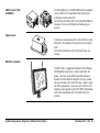
The type and serial number of your product are indicated on the label on the base of the
product.
Enter the model and serial number in your manual and always refer to this information when
you need to contact your agency or Leica Geosystems authorised service workshop.
Type: MPC1310 Machine Computer
Serial No.:
_______________
Type: MSS1200 Dual-Axis Slope Sensor
Serial No.:
_______________
Type: TCPS27S Ruggedised Radio Modem
Serial No.:
_______________
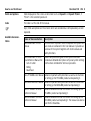
Symbols
The symbols used in this manual have the following meanings:
Type
Danger
Warning
Caution
)
Trademarks
•
•
•
•
•
Description
Indicates an imminently hazardous situation which, if not avoided, will
result in death or serious injury.
Indicates a potentially hazardous situation or an unintended use which,
if not avoided, could result in death or serious injury.
Indicates a potentially hazardous situation or an unintended use which,
if not avoided, may result in minor or moderate injury and/or appreciable material, financial and environmental damage.
Important paragraphs which must be adhered to in practice as they
enable the product to be used in a technically correct and efficient
manner.
Windows is a registered trademark of Microsoft Corporation
GOMACO is a registered trademark of Gomaco Corporation, USA
Wirtgen is a registered trademark of Wirtgen Group, Germany
MOBA is a registered trademark of MOBA Mobile Automation AG, Germany
Vögele is a registered trademark of Wirtgen Group, Germany
All other trademarks are the property of their respective owners.
Introduction
PaveSmart 3D UM 3
Table of Contents
PaveSmart 3D UM 4
Table of Contents
In this manual
Chapter
Page
1
How to use this Manual
2
Getting Started
10
2.1
2.2
2.3
2.4
2.5
2.6
2.7
2.8
2.9
2.10
2.11
2.12
10
12
25
27
32
39
45
46
47
51
58
63
3
4
Preparing the Leica PaveSmart 3D System
Operating the MPC1310 Machine Computer
Rules for Defining Projects
Preparing the Leica PaveSmart 3D Software for the Current Project
Selecting Design Reference Lines
Continue Working Depending on the Current Machine Position
Positioning the Machine for Production
Taking As-Built Measurements
Leapfrogging (Swapping TPS)
Checking Instrument Setup Quality and Status
Backup and Restore
Stopping Work (End of Daily Production)
6
System Components, Diagrams, Software Description
64
3.1
3.2
3.3
64
69
81
Hardware Descriptions
System Wiring Diagrams
Software Description
Troubleshooting
84
5
6
Care and Transport
90
5.1
5.2
5.3
5.4
90
90
91
91
Safety Directions
6.1
6.2
6.3
6.4
6.5
6.6
6.7
6.8
6.9
7
Index
Table of Contents
Transport
Storage
Cleaning and Drying
Maintenance
General
Intended Use
Limits of Use
Responsibilities
Software Licence Agreement
Microsoft End User License Agreement ("EULA")
Hazards of Use
Electromagnetic Compatibility EMC
FCC Statement, Applicable in U.S.
Technical Data
92
92
92
93
94
95
96
107
111
113
116
118
PaveSmart 3D UM 5
How to use this Manual
PaveSmart 3D UM 6
1
How to use this Manual
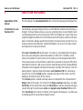
Applicability of this
manual
This User Manual is for Leica PaveSmart 3D, for use to control paving and milling machines.
Introduction to Leica
PaveSmart 3D
Conventionally, paving and milling machines are controlled for elevation and steering by a
stringline. These are staked-out by a survey crew; positioning the pins and setting the wires
is a demanding and error-prone surveying task. When the stringlines are in place, they cause
a significant logistical problem for concrete delivery and further poses a safety risk for operatives. Furthermore, damage caused to the stringline, from personnel or concrete trucks can
seriously interfere with production. Undetected problems can result in the costly removal
and replacement of expensive material.
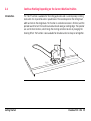
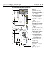
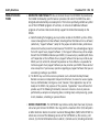
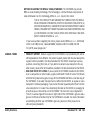
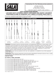
With Leica’s PaveSmart 3D control system, the machine is controlled without stringlines.
One or two Leica Geosystems robotic total stations or GNSS (GPS / GLONASS) sensors
measure the position of specific points on the machine at a rate of approximately 10 Hz.
These measurements are transmitted by radio to the Leica Machine Computer (MPC1310),
mounted on the machine. High-accuracy machine-mounted slope sensors provide additional
information on the longslope (mainfall) and crossslope (crossfall) of the machine. From this
pool of position, height and slope information, Leica PaveSmart 3D then continuously
calculates the current or Actual position, elevation and slopes of the machine, and the
heading (or direction of travel) of the machine.
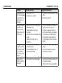
These Actual position, elevation and slope values are compared to the computerised 3D
Design model of the project. The results of this Design-vs-Actual comparison, are called
Corrections. These represent the amount of Corrections (in position, elevation and slope)
required to bring the machine back online and ongrade. Leica PaveSmart 3D transmits
these Corrections to the machine controller, which regulates the hydraulics, in a similar way
to controlling with the conventional stringline sensors.
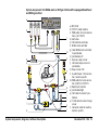
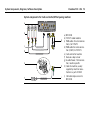
b
a
c
i
d
h
k
e
j
f
g
a) MPC1310
b) CAD-PC
c) USB storage device
d) Project data
e) Reference point list
(OnBoard or hand-held application)
f) TCPS27 or FreeWave Radio modem
g) Measured value Hz, V, Dist
h) Slope sensor
i) Actual longslope & crossslope of the
machine
j) Machine
k) Parameters for position and height
Contents of this
manual
The Leica PaveSmart 3D User Manual is designed into four key sections. System setup
Information is now presented in a step-by-step format:
1.Getting Started (Daily Operations, Project Setup, Hints and Tips)
2.System Components (Diagrams & Software Description)
3.Troubleshooting (Detailed Troubleshooting Chart)
4.Care and Transport / Safety Directions
Path
Work: Offset\Steer stands for this working sequence:
From the Work dialog select Offset and then select Steer.
Leica PaveSmart 3D paths always start either in the Work dialog or in the Menu dialog.
Screen
Work\Elevation Offsets\Steer Offsets describes the name of the screen.
How to use this Manual
PaveSmart 3D UM 7
How to use this Manual
PaveSmart 3D UM 8
Fields and options
Fields displayed on the screen are described such as <Speed:> or <Speed: ft/min>, if
"ft/min" is the selected speed unit.
Index
The index is at the end of the manual.
)
Keys, fields and options on the screens which are considered as self-explanatory are not
explained.
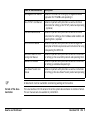
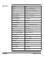
Available documentation
Name of documentation
Description
Leica PaveSmart 3D User
Manual
All instructions required in order to operate the system to a
basic level are contained in this User Manual. It provides an
overview of the system together with technical data and
safety directions.
Leica PaveSmart 3D TechOverall comprehensive guide to the system functions.
nical Reference Manual for : Included are detailed descriptions of special system settings
• Curb & Gutter
and functions intended for technical specialists.
• Milling
• Road Paver
Leica TPS1200+ User Manual Contains important safety directions as well as instructions
for setting up the TPS1200+ product and operating it.
Leica MNS1200 User Manual Contains important safety directions as well as instructions
for setting up the MNS1200 product and operating it.
Leica TPS1200+ Technical
Reference Manual
Contains detailed technical instructions for setting up the
TPS1200+ product and operating it.
Leica GPS1200+ Technical
Reference Manual
Contains detailed technical instructions for setting up the
GPS1200+ product and operating it. The manual can also be
used for the PowerBox.
)
Format of the documentation
How to use this Manual
Name of documentation
Description
Leica Mguide User Manual
Contains instructions for setting up the Mguide onboard
application for TPS1200+ and operating it.
Leica TCPS27 User Manual
Contains important safety directions as well as technical
instructions for setting up the TCPS27 product and operating
it. (optional)
FreeWave Radio Manual
Contains important safety directions as well as technical
instructions for setting up the FreeWave radio modems and
operating them. (optional)
MPC1310 User Manual
Contains important safety directions as well as a general
description of technical processes and instructions for using
and operating the MPC1310.
Leica GNSS Machine Positioning User Manual
Contains important safety directions as well as instructions
for setting up the Leica GNSS products and operating them.
GeoPad User Manual
Contains important safety directions as well as instructions
for setting up GeoPad and operating it.
Leica PowerTracker User
Manual
Contains important safety directions as well as instructions
for setting up the Leica PowerTracker product and operating
it.
All documents must be read before commencing working on the machine.
The Leica PaveSmart 3D CD contains the entire system documentation in electronic format.
The user manuals are also available in printed form.
PaveSmart 3D UM 9
Getting Started
PaveSmart 3D UM 10
2
Getting Started
2.1
Preparing the Leica PaveSmart 3D System
Further reading
Refer to the Leica PaveSmart 3D Technical Reference Manuals, the GeoPad User Manual or
to the MGuide1200 Application Program Manual on how to perform a Resection (Free
Station), Known Point setup and how to take As-Built measurements.
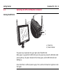
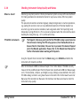
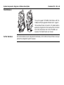
Before production
Connect the MPC Computer: Attach the MPC1310 computer to the machine. Connect
power, radio- and CAN cables if available.
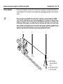
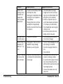
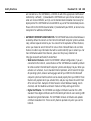
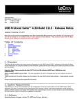
Set up all required sensors: TPS and GNSS (GPS / GLONASS) reference station with the
required accessories as battery, radio and cables. Ensure all TPS are running either in MGuide
with the appropriate configuration set, or correctly configured when working with a handheld application GeoPad.
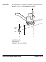
a
b
a) Max. 200m (600 ft)
b) Min. 10m (30 ft)
Set up Fixpoint Prisms over suitable fixpoints, ready for Free Station or Known Point
Setups.
Once all TPS and prisms are set up, go to each of them, Level and perform a Resection
(Free Station) or Known Point Setup (refer to the MGuide1200 Application Program
Manual or the GeoPad User Manual, depending on your type of instrument / work flow).
If working with GNSS (GPS / GLONASS) start the reference station to obtain correction data
for the GNSS machine sensor (refer to the Leica MNS1200 or the Leica GNSS Machine Positioning User Manual).
At the Leica PaveSmart 3D computer: In the dialog Work\Sensor\Arrange select which
sensor will be used as <Primary> and optionally as <Secondary> and <Spare>.
)
Getting Started
Switch on machine and allow hydraulic system to warm to a suitable operating temperature before starting work.
PaveSmart 3D UM 11
Getting Started
2.2
PaveSmart 3D UM 12
Operating the MPC1310 Machine Computer
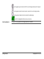
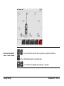
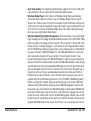
Starting the MPC1310
i
iF
W
a
b
a) Power key
b) Power indicator
The power key is located on the upper right side of the MPC1310.
When power is supplied for the MPC1310, press the power key to start the MPC1310. After
pressing the key, the power indicator LED will show green, and the MPC1310 will start
booting-up.
Ensure that there is sufficient power supply. If not, switch on the machine's ignition or start
the engine.
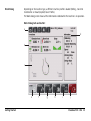
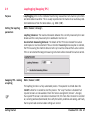
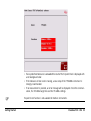
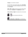
Work Dialog
Depending on the machine type, a different machine profile is loaded (Milling-, Concrete
Curb&Gutter- or Road (Asphalt) Paver Profile).
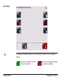
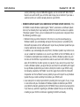
The Work dialog screen shows all the information needed while the machine is in operation.
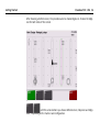
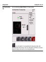
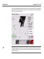
Work Dialog Curb and Gutter:
a
d
b
c
e
Getting Started
f
g
h
i
j
PaveSmart 3D UM 13
Getting Started
PaveSmart 3D UM 14
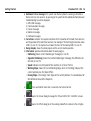
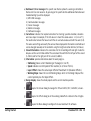
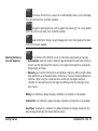
a) Dashboard / Error messages: the specific icon flashes yellow if a warning is detected or
flashes red if an error occurres. By pressing on the specific button additional information and
troubleshooting tips will be displayed.
1.) MPC1310 messages
2.) Communication messages
3.) Sensor messages
4.) Machine messages
5.) Software messages
b) Corrections: indicates the required corrections for the elevation of the mold (front and rear)
and the position of the mold (front and rear). For example, if the front height correction shows
-0.013 (in m or ft), the machine has to lower the front of the mold by 0.013 (in m or ft).
c) Design display: shows the whole project and the current machine position.
d) Information: provides information about the work progress.
• Stationing shows current Stationing or Chainage (in m or ft).
• Opposite Stationing shows the inverted Stationing or Chainage, the difference to
the end (in m or ft).
• Speed indicates current Speed of the machine (in m/min or ft/min).
• Working Slope shows the current Working Slope, which is the Design Slope at the
current position plus the Slope Offset.
• Desing Slope is the Design Cross Slope at the current position. It's calculated out of
the ReferenceLine and the SlopeLine.
e)
Press and hold for more than 1 second to start active Control.
f)
opens the Sensor dialog to manage the TPS and GNSS (GPS / GLONASS) sensors.
g)
opens the Offset dialog to set the working mold offsets relative to the stringline.
h)
opens the Menu dialog to configure the Leica PaveSmart 3D software.
i)
opens the Tuning dialog to set the hydraulics parameters for the machine.
j)
)
Getting Started
press and hold for more than 1 second to stop active Control and in a second step
to close the software and shut down the MPC1310.
Do not power off the MPC1310 by holding down the Power Key! Always shut down the
MPC1310 by using the Exit button to ensure all important project data are saved.
PaveSmart 3D UM 15
Getting Started
PaveSmart 3D UM 16
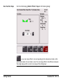
Work Dialog Milling:
a
d
b
c
e
f
g
h
i
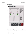
a) Dashboard / Error messages: the specific icon flashes yellow if a warning is detected or
flashes red if an error occurres. By pressing on the specific button additional information and
troubleshooting tips will be displayed.
1.) MPC1310 messages
2.) Communication messages
3.) Sensor messages
4.) Machine messages
5.) Software messages
b) Corrections: indicates the required corrections for the elevation and cross slope of the milling
head and the position of the milling head. For example, if the height correction shows 0.010
(in m or ft), the machine has to lower the milling head by 0.010 (in m or ft). The values and
settings are exactly the same as those displayed on the machine controller and can be changed
manually on the controller or automatically through PaveSmart 3D.
c) Design display: shows the whole project and the current machine position.
d) Information: provides information about the work progress.
• Stationing shows current Stationing or Chainage (in m or ft).
• Opposite Stationing shows the inverted Stationing or Chainage, the difference to
the end (in m or ft).
• Speed indicates current Speed of the machine (in m/min or ft/min).
• Milling height is the calculated height of the control point at the mast foot point.
• Design height is the project design height at the actual position.
• Layer Offset is the height offset, which is added to the design elevation constantly.
• Slope Offset is the active offset when working with a slope side.
Getting Started
e)
opens the Sensor dialog to manage the TPS and GNSS (GPS / GLONASS) sensors.
f)
opens the Offset dialog to set the working mold offsets relative to the stringline.
g)
opens the Menu dialog to configure the Leica PaveSmart 3D software.
h)
opens the Tuning dialog to set the hydraulics parameters for the machine.
i)
press and hold for more than 1 second to stop active Control and in a second step
to close the software and shut down the MPC1310.
PaveSmart 3D UM 17
Getting Started
)
PaveSmart 3D UM 18
Do not power off the MPC1310 by holding down the Power Key! Always shut down the
MPC1310 by using the Exit button to ensure all important project data are saved.
Work Dialog Road Paver:
a
d
b
c
e
f
g
h
i
j
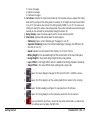
a) Dashboard / Error messages: the specific icon flashes yellow if a warning is detected or
flashes red if an error occurres. By pressing on the specific button additional information and
troubleshooting tips will be displayed.
1.) MPC1310 messages
2.) Communication messages
3.) Sensor messages
4.) Machine messages
5.) Software messages
b) Corrections: indicates the required corrections for steering / position deviation, elevation
and cross slope. For example, if the Set value is 1.0 and the actual value is 1.1 (in m or ft),
the machine has to lower the tow arm until the set- and actual values are both the same (1.0).
The values and settings are exactly the same as those displayed on the machine controller and
can be changed manually on the controller using the height correction buttons (Set Value).
c) Screed Information: indicates the corrections for the Screed Edge left and right. Inside the
box you see the current total width of the screed and the width for the left part of the screed
(1.250 m) and for the right part of the screed (1.260 m).
d) Information: provides information about the work progress.
•
•
•
•
Stationing shows current Stationing or Chainage (in m or ft).
Speed indicates current Speed of the machine (in m/min or ft/min).
Layer Offset shows the actual layer offset of PaveSmart 3D (Elevation Offsets).
Working Slope shows the current Working Slope, which is the Design Slope at the
current position plus the Slope Offset.
e) Design display: shows the whole project and the current machine position.
Getting Started
f)
opens the Sensor dialog to manage the TPS and GNSS (GPS / GLONASS) sensors.
g)
opens the Offset dialog to set the working mold offsets relative to the stringline.
h)
opens the Menu dialog to configure the Leica PaveSmart 3D software.
PaveSmart 3D UM 19
Getting Started
)
PaveSmart 3D UM 20
i)
opens the Tuning dialog to set the hydraulics parameters for the machine. The
tuning of the hydraulic is usually done at the controller.
j)
press and hold for more than 1 second to stop active Control and in a second step
to close the software and shut down the MPC1310.
Do not power off the MPC1310 by holding down the Power Key! Always shut down the
MPC1310 by using the Exit button to ensure all important project data are saved.
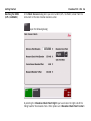
Menu dialog
)
In all dialogs, the following buttons are used to navigate, confirm or reject changes to
settings.
confirm your changes to system
settings and continue.
Getting Started
reject your setting changes and go
back to previous dialog.
PaveSmart 3D UM 21
Getting Started
PaveSmart 3D UM 22
The Menu dialog offers several opportunities to configure the Leica PaveSmart 3D software.
The machine and the current task have an influence on the configuration required.
contains all project and job relevant dialogs to manage jobs, log files, as-built
recordings and backups.
To define with which sensor configuration (TPS, TPS/GNSS) is being used and to
configure all attached sensors.
General settings such as units etc.
To define the machine dimensions, locks and stops, production tolerances and the
machine tuning.
Access to the data flow and the external radio configuration tools.
To enable the protected dialogs (if disabled) and opens dialog to enter the password.
Contains various tools for service personal only. Customer access only under Leica
supervision.
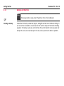
Config dialog
Optional protected by a password which can be set in the Settings / General dialog,
containing settings which are usually not used in daily production and should only be edited
by a trained system administrator (n.b. Default password = 007).
Service dialog
Password protected menu for Leica support personnel only.
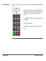
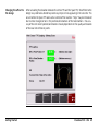
Numeric keyboard
By pressing on any editable value in a dialog, the numeric keypad will be opened automatically.
Edit the current, or enter a new value and press OK. The
keyboard will close and the new value will be used. If you
have made a mistake, simply press again to edit the
number.
+/- key toggles the sign of the number between positive
and negative.
DEL deletes entered values.
ESC abandons your changes, and reverts to the initial
value.
Getting Started
PaveSmart 3D UM 23
Getting Started
Text keyboard
PaveSmart 3D UM 24
By pressing in text edit field the text keypad will be open automatically.
Enter or edit text and press OK.
This keyboard operates similarly to the numeric keypad. Refer to "Numeric keyboard", page
23 for more information.
2.3
Overview
Rules for Defining Projects
Leica PaveSmart 3D requires accurate design data to be able to control the machines movements. The machine is only capable of following the information contained within the design
data, therefore the quality of the final product is directly influenced by the quality of the
data used.
The control process is also influenced by the design data. The greater the number of
segments contained within the design the greater the processing power required to
run the system. A balance must be found between the number of segments required to
define the design and the processing power it will require.
The recommendations detailed below must be followed when creating designs.
Without following these rules Leica Geosystems cannot guarantee good quality paving
performance.
Angle change between
segments
Getting Started
Leica PaveSmart 3D is capable of using designs in a 3 dimensional format which may contain
• Straights
• Arcs
• Clothoids, entry and exit as well as partial
• Cubic parabolas
• Full/Partial Bloss curves (parabola of degree five)
Using these shapes only a small number of segments are required to define any 3 dimensional shapes.
PaveSmart 3D UM 25
Getting Started
PaveSmart 3D UM 26
Not all CAD systems are capable of producing curved 3-dimensional polylines. To overcome
this curved line segments are broken up into a number of individual straight-line segments.
The closer these straight segments are together the more accurate the original design data
is approximated.
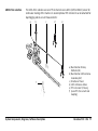
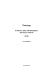
• When approximating curved 3 dimensional line segments the angle change between two
connected line segments must never be greater than 1 degree (1°).
• When defining a straight line it is not necessary to add more points in the middle of a line.
c
b
a
c
a) Reference line
b) Line segments
c) Angle change
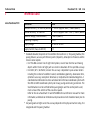
Number of Segments
1°
The number of segments contained within a single stringline must not exceed 2000 individual elements. It is possible to have multiple stringlines on the same layer but each individual stringline must not exceed 2000 elements.
If a single stringline requires more than 2000 elements it must be broken into more than
one stringline, which must be paved separately.
2.4
Preparing the Leica PaveSmart 3D Software for the Current Project
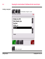
Creating a new project
start from Menu: Projects \ Current
create a new project
Getting Started
PaveSmart 3D UM 27
Getting Started
PaveSmart 3D UM 28
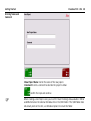
Entering Name and
Comment
<New Project Name:> enter the name of the new project.
<Comment:> enter a comment to describe the project in detail.
confirm the input and continue
)
Before creating a new Project name, you must first have the design data available in DBX or
LandXML format on the external USB data stick in the \DBX folder. If the \DBX folder does
not already exist on the stick, use Windows Explorer to create the folder.
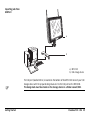
Importing jobs from
USB Port
a
b
a) MPC1310
b) USB storage device
)
Getting Started
The USB port (labelled USB A) is located on the bottom of the MPC1310. Connect your USB
storage device with the prepared design data on it to the USB port on the MPC1310.
The design data must be stored on the storage device in a folder named \DBX.
PaveSmart 3D UM 29
Getting Started
PaveSmart 3D UM 30
Selecting Design Type
and Layer
<Design Type> defines the job type you want to work with:
• <StringLine> is selected as the default <Design Type>.
• <StringLine Job> shows the currently selected StringLine job. Only one layer from the
stringline job can selected at a time. Select the appropriate layer from the <Layer>
dialog.
confirm the selections and continue.
Selecting the current
Project
The newly created project is automatically highlighted as the current project. If a different
project is required it may be selected.
confirm the selection and continue.
New Project created, but not selected. Back to Menu.
Getting Started
PaveSmart 3D UM 31
Getting Started
PaveSmart 3D UM 32
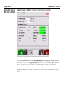
2.5
Selecting Design Reference Lines
Design dialog
From the Work dialog doubleclick on the Design window to see the Work \ Design dialog:
set all deviations to zero. This function is not available for all machine types.
to chose a reference line, a slope line (or automatically chosen), and screed edge
lines (only for NaviTronic controller available).
change the working direction (with or against the stationing). This is only needed
for the one TPS or one GNSS (GPS / GLONASS) solution.
leads to the Work \ Design \ Graphics dialog where some more graphical functions
such as 3D view are available.
Selecting ReferenceLine and SlopeLine
•
•
The selection of the Reference Lines is either done automatically or manually.
Automatically means the system is determining automatically the next reference line on
the left- and the right side of the machine (or its height control point) to calculate the
design height- and slope.
Manually you chose the ReferenceLine and optional a SlopeLine. When using the Road
Paver profile this can be disabled in Menu \ Preferences \ General <Disable Automatic Line
Selection>. When using the screed extention control with the Vögele NaviTronic
controller, the procedure asks for the Edge Line definition after the steering line has
been chosen.
Milling: Line Selection is always manually, Automatic Line Selection is not available.
Curb&Cutter: Line Selection is always manually, Automatic Line Selection is not available.
Road Paver: Automatic line selection is by default disabled. By enabling, PaveSmart 3D is
determining automatically the relevant ReferenceLines.
Getting Started
PaveSmart 3D UM 33
Getting Started
PaveSmart 3D UM 34
After choosing a ReferenceLine, the procedure asks to choose EdgeLines. Choose the EdgeLine for both sides of the screed.
with the arrow buttons you choose ReferenceLine, SlopeLine and EdgeLines , depending on the machine and configuration.
use the graphical pan function to shift the current design window over the project.
use the graphical zoom function to zoom in and out the current design window.
use the graphical rotation function to rotate the whole design.
confirm the highlighted ReferenceLine and continue.
Selecting EdgeLines
Getting Started
This feature is only available for the Voegele NaviTronic controller.
PaveSmart 3D UM 35
Getting Started
PaveSmart 3D UM 36
Entering offsets
start in Work \ Offset.
)
The offset dialog can look slightly different depending on the loaded profile and the
attached sensors, the functionality is the same.
increase or decrease individually the <Front> or <Rear> Working Offsets step
by step.
increase or decrease the <Front> and the <Rear> Working Offsets together
step by step.
Press the <Front> or <Rear> edit field to get the numeric keyboard.
Getting Started
PaveSmart 3D UM 37
Getting Started
PaveSmart 3D UM 38
Enter a new offset and press OK.
from Work \ Elevation Offsets \ Steer Offsets
Enter the <Front> or <Rear> steering offsets in the same way as the elevation offsets.
from Work \ Elevation Offsets \ Slope Offset
Enter the <Cross Slope> offset in the same way as the elevation offsets. The cross slope
offset determines catch / spill curb if there is no cross-slope information in the job.
2.6
Continue Working Depending on the Current Machine Position
Introduction
The "Here" function is available for the milling application and is used especially in milling
tasks when it is required to work in parallel lanes. The lanes depend on the milling head
width and not on the design data. The function is used when one lane is finished, and the
operator wants to turn the machine around and work along an existing edge. The operator
can use the Here function, which brings the steering correction to zero by changing the
steering offset. The function is also available for elevation and cross slope or all together.
Getting Started
PaveSmart 3D UM 39
Getting Started
Here Function Steering
PaveSmart 3D UM 40
From the Work dialog go Work: Offsets \ Steer to the following dialog:
The setting <Reference: Right> sets the offsets to be measured to the right side of the
milling head. Other options are: <Reference: Center> and <Reference: Left>.
a new offset value is set corresponding to the indicated correction. After pressing
the button, the correction is zero. The offset value is the distance between the reference
line and the current machine position.
Here Function Road
Paver / Steer Offsets
: The Screed Offsets and the steering offset are adjusted individually.
sets an Offset that makes the correction zero.
: All 3 offsets are changed simultaniously / in parallel.
Getting Started
PaveSmart 3D UM 41
Getting Started
Here Function Elevation
PaveSmart 3D UM 42
From the Work dialog go Work: Offsets to the following dialog:
a new cutting depth is set corresponding to the indicated correction. After
pressing the button, the correction is zero. The cutting depth is the difference in elevation
between the design surface and the current milling head elevation.
Here Function Slope
From the Work dialog go Work: Offsets \ Slope to the following dialog:
a new cross slope offset is set corresponding to the indicated correction. After
pressing the button, the correction is zero. The cross slope offset is the difference between
the design slope and the current cross slope of the milling head.
Getting Started
PaveSmart 3D UM 43
Getting Started
Over all Here Function
PaveSmart 3D UM 44
From the Work dialog press on the graphic to get to the following dialog:
in the Work: Design Dialog all of the above mentioned Here Functions are
combined. The Here button in the Graphic dialog sets the steering offset, the cutting depth
and the slope offset in that way, that all the corrections are zero.
2.7
Positioning the Machine for Production
Get machine onto line
and level
Note the current deviations with as-built checks. Liaise with the machine operator to get
machine onto line and level.
Curb and Gutter
Ensure that the machine controller is set to the correct steering mode (e.g. Leica 3D Mode),
with Steer & Elev. Sensitivities set to Minimum and all control loops set to Automatic. Start
Leica PaveSmart 3D automatic control by pressing the START button for one second.
Milling
Scratch the surface with the drum and dial in the offset you calculated with your as-built
checks. Ensure the controller is showing plausible actual values. Depending on application
and material, go to your milling depth by start manually or directly in Automatic. Check
milling depth immediately with some As-Built Measurements.
Road Paver
Ensure the underlying material to set the screed onto is on the correct height and the tow
arms are in the correct position for the paving depth. Start paving in manual mode and the
check surface height (manual corrections). When the desired height is achieved and the
screed has found its position, set the corrections (set values) in conjunction with the actual
value and go into automatic.
Automatic steering- and screed edge control:
Position the machine within 10 cm accuracy in parallel to the project.
Use the HERE function (
) in the offset dialog to adjust the screed deviations after positioning the screed edge to its desired width.
Getting Started
PaveSmart 3D UM 45
Getting Started
PaveSmart 3D UM 46
2.8
Taking As-Built Measurements
Description
To check elevation and position during production, Leica PaveSmart 3D has an integrated
as-built (Control) function to replace the manual dipping method used when working on
string line. Regular, independent as-built measurements are essential to verify product is in
project tolerances.
)
Measurements are only possible if the instrument is correctly positioned and orientated
within the project coordinate system (Free Station or Known Point setup)
Taking As-built control
measurements
Refer to the MGUIDE User Manual for the instrument type and for detailed instructions on
making as-built measurements. Customers using PowerTracker instruments refer to the
PowerTracker User Manual and the Geo-Pad User Manual or Site Foreman User Manual on
how to take As-built measurements.
Display and recording
As-built control measurements
Immediately after an As-built control measurement has been made the results can be seen
in the Work\Design dialog. The results are also recorded in the active project folder in the
Asbuilt.abr file. Work: Menu \ Projects \ AsBuilt, and can be exported to provide a permanent quality-assurance record.
)
Care must be taken when taking as-built measurements very close to a free-standing edge
on freshly slipformed concrete - this may give misleading results, due to the uncontrollable
slump of the material at the unsupported edge.
2.9
Leapfrogging (Swapping TPS)
Purpose
Leapfrogging refers to the method of transferring measurement of a machine prism from
one total station to another. This is usually required when the machine has reached a predetermined distance from the total station, e.g. 100m (300').
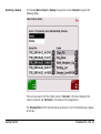
Setting the leapfrog
parameters
Work \ Sensor \ Arrange \
Leapfrog tolerance: The maximum deviation between the currently measured prism coordinates and the newly measured prism coordinates must be set.
Use shortest measuring distance: The details of the TPS to be removed from active
control process must be selected. If the use shortest measuring distance option is selected,
the TPS measuring the shortest distance to the prism will be removed from active control.
If this is not selected the longest measuring instrument will be removed from active control.
Swapping TPS - making
a leapfrog
)
Getting Started
Work \ Sensor \ LEAP \
The leapfrog function is a fully automated process. The operator must hold down the
<LEAP> button for 1 second to start the process. The "Leap" function is disabled if all
required sensors are not available. Check the Sensor arrangement (Sensors \ Arrange).
If a required TPS sensor is not visible in PaveSmart 3D, first check the instrument is switched
on, correctly positioned/orientated, then verify the battery condition and cabling, and finally
that required radio communication settings are correct.
PaveSmart 3D UM 47
Getting Started
PaveSmart 3D UM 48
The system automatically removes the required instrument (nearest or furthest measuring)
out of active control and sets it to the spare sensor, replacing it with the instrument previously in the spare sensor location.
)
Before leapfrogging a TPS instrument, the machine must be at a stand-still. If the machine
is moving the spare instrument may not be able to lock onto the prism and erroneous measurements may result.
Changing the offset to
the design
Getting Started
After calculating the deviation between the Active TPS and the Spare TPS, the offsets to the
design may need to be altered to prevent any steps or lines appearing in the concrete. This
occurs before the Spare TPS takes active control of the machine. "Steps" may be introduced
due to minor changes/errors in the positions/orientations of the total stations - the accuracy of the instrument position/orientation is heavily dependent on the quality and location
of the local site reference points.
PaveSmart 3D UM 49
Getting Started
Auto 3D
Offset adjustment
PaveSmart 3D UM 50
Work \ Sensor \ Leapfrog \ Auto 3D
<Auto 3D> changes the current working offsets by subtracting the deviation between the
current position and the new position from the current working offsets in both steering
(front and rear) and elevation (front and rear) so no steps appear in the concrete.
)
Auto Elevation
Offset adjustment
Auto 3D is the recommended method of adjusting offsets when an instrument is
taken out of active control.
Care must be taken to manually remove this small offset changes if absolute position control is important.
Work \ Sensor \ Leapfrog \ Auto Elev.
The Auto Elevation button will change the elevation offsets by the difference in height
between the active measurement and the new measurement at the front and rear of the
mold.
The steering offsets will remain as they were before the instrument swap.
Auto Steer
Offset adjustment
Work \ Sensor \ Leapfrog \ Auto Steer
The Auto Steer button will shift the position in the front and rear steer offsets by the difference between the existing deviation to the reference line and the new deviation to the
reference line. The elevation offsets will remain as they were before the instrument swap.
Manual Offset
adjustment
No change is made to the offsets. The operator is required to make any changes in the
offsets manually.
2.10
Checking Instrument Setup Quality and Status
When to check?
Observing survey best practice is the key to maximum system accuracy with Leica PaveSmart
3D. Poorly positioned or orientated instruments may have a serious effect on product
quality.
This procedure should be carried out regularly, ideally during breaks in machine operations,
e.g. waiting for concrete, to ensure no undetected movement of the total stations has
occurred (e.g. due to excessive vibrations, bad sub-ground under the tripod, high wind,
temperature cycling effects etc). This is also very important when the instrument has been
standing for a long time (e.g. > 2 hr) at the same setup.
TPS1200+ instruments
)
The fixpoint (reference point) job for the TPS1200+ setup is only stored on
the instrument. During the TPS setup process (Free Station/Resection or
Known Point & Orientation) the user has to preselect the desired fixpoint
job in the MGuide application. Please refer to the MGuide User Manual for
further information about working with Fixpoints.
Using the Tiepoint Check function from the Work dialog press SENSOR and define the
instrument with should be verified.
)
Getting Started
Refer to the MGuide 1200 User Manual Chapter 5 for further details. TPS1200+ can only
measure to the predefined point from the fixpoint job (see MGuide 1200 User Manual page
4-15). The horizontal-, distance- and height accuracy settings are also defined in the same
TPS1200+ dialog. Customers using PowerTracker instruments refer to the PowerTracker User
Manual and the Geo Pad User Manual or Site Foreman User Manual on how to check the
instrument setup quality.
PaveSmart 3D UM 51
Getting Started
PaveSmart 3D UM 52
Tiepoint Check
After the selection of the instrument press CHECK
Attention: The Tiepoint Check can be only used with the TPS not with GNSS.
Wait for the results to be displayed - this will take several seconds as the instrument turns
to the required position and measures the prism. The instrument will then return to its
previous position. The result is displayed after the TPS measurement to the preselected
fixpoint. If the result is within the tolerance the Correction is displayed with a green background color.
•
•
•
)
Getting Started
If one predefined tolerance is exceeded the result of the Tiepoint Check is displayed with
a red background color.
If the tolerance of one result is too big, a new setup of the TPS1200+ instrument is
strongly recommended.
If no measurement is possible, an error message will be displayed. Check the communication, the TPS1200+ target line and the TPS1200+ settings.
Tie point check function is not available for RedLine instruments.
PaveSmart 3D UM 53
Getting Started
Checking the Status of
GNSS (GPS / GLONASS)
PaveSmart 3D UM 54
In Menu: Sensors \ GNSS the following status information is available:
The machine operator enters in the <Position Quality:> the maximum value for the position tolerance and in the <Height Quality:> the maximum value for the height tolerance.
As soon as these values are exceeded, an error message is sent to the dashboard.
<Firmware version:> shows the current firmware version on the GNSS (GPS / GLONASS)
sensor.
<Timestamp:>, the current GNSS time is indicated here.
The number of satellites, which are theoretically available are listed in <#sats available:>.
Out of these a certain number of satellites are sending data to the GNSS (GPS / GLONASS)
receiver <#sats tracked:>.
<HDOP:>, <VDOP:> and <Status:> are geometrical values about the satellite constellation.
From those values the <Pos Quality:> and the <Height Quality:> are calculated.
<Easting:>, <Northing:> and <Height:> are the coordinates of the current sensor position.
and
are used to switch between the different sensors.
the <Position Quality:> and <Height Quality:> are set to the default values.
Getting Started
PaveSmart 3D UM 55
Getting Started
Benching for GNSS
(GPS / GLONASS)
PaveSmart 3D UM 56
In the Work: Sensors dialog when you select a GNSS (GPS / GLONASS) sensor from the
instrument list the Bench button becomes active:
open the following dialog:
By selecting the <Elevation Check Point: Right> you have chosen the right side of the
milling head for the elevation check. Other options are: <Elevation Check Point: Center>
and <Elevation Check Point: Left>. The selected spot on the milling head is then measured
or brought directly in relation to the control point hub.
The <Reference Point Elevation> is manually entered by the operator.
the sensor starts measuring. This may take a few seconds as several measurements are taken during this time.
The <Measured Check Point Elevation> is the current elevation of the milling head, measured with the GNSS (GPS / GLONASS) sensor.
The difference between the measurement and the reference point elevation is the <Current
Sensor Elevation Offset>.
continues and accepts the current sensor elevation offset. From now on this offset
is considered in the calculation until a new offset is determined with the Bench function
again.
continues and rejects the currently determined offset. The before used offset will
be used again.
Getting Started
PaveSmart 3D UM 57
Getting Started
2.11
)
Creating a Backup
PaveSmart 3D UM 58
Backup and Restore
the Backup button is only active if PaveSmart 3D is in the Config level.
A PaveSmart 3D Backup contains all projects, all logfiles and all current software settings. It
can be used to re-establish a certain state on the machine computer for trouble shooting
purposes. The Backup is also very useful to check the current state for service purpose. For
example the user can send a Backup to the Leica service personnel to detect a problem.
In the dialog Menu: Projects \ Backup the operator chooses <Backup> to get to the
following dialog:
An <Internal> Backup is stored on the local drive on the machine computer.
An <External> Backup is stored on the external USB storage device.
Getting Started
PaveSmart 3D UM 59
Getting Started
PaveSmart 3D UM 60
To create a Backup may take up to a few minutes, depending on the amount of data that's
stored on the machine computer. When finished a confirmation message will be shown. In
this message the file name of the Backup zip-file is displayed.
Restoring a Backup
In the dialog Menu: Projects \ Backup the operator selects <Restore> to get to the
following dialog:
There are two sources for the restore process: <Internal> is the local storage on the
machine computer and <External> is the external USB storage device.
The <Backup Files:> of the selected source are shown in a list. The latest Backup is always
on the top.
Getting Started
PaveSmart 3D UM 61
Getting Started
PaveSmart 3D UM 62
In the <Content> window all the projects of the currently selected Backup file are listed.
restores the selected Backup and overwrites all projects, all logfiles and all current
software settings. Before the current settings and data are over-written, an internal Backup
is automatically done.
2.12
Stopping Work (End of Daily Production)
After Production
To Stop Tracking, press and hold Stop for one second.
The Stop button now displays Exit. Press and hold Exit for more than 1 second to display
the Shutdown/Restart options dialog. Select Shutdown to exit PaveSmart 3D and poweroff the MPC1310.
)
Do not power off the MPC1310 by holding down the Power Key! Always shut down the
MPC1310 by using the Exit button to ensure all important project data are saved. Incorrect
shutdown of the MPC1310 may risk unexpected data loss or corruption of the Windows
system files!
After approx. thirty seconds when the MPC1310 display is black, turn off power using the
power key.
Disconnect power/data cables, radio cables.
Store all equipment in the MPC1310 carrycase.
Fit dust/water caps for machine-mounted connectors, if provided, to prevent rain or
condensation build-up which may lead to electrical problems.
)
Getting Started
Due to the risk of theft, lightning-strikes or vandalism, we strongly recommend removal of
the radios, GNSS and MPC1310 computer overnight.
PaveSmart 3D UM 63
System Components, Diagrams, Software Description
PaveSmart 3D UM 64
3
System Components, Diagrams, Software Description
3.1
Hardware Descriptions
General information
Even though the hardware components are designed for rough conditions, the components
have to be treated and transported in a careful manner. Therefore use the designated packaging for transport and study the relevant documentation for cleaning and maintenance
work (refer to "5 Care and Transport").
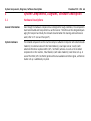
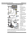
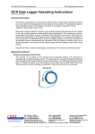
System hardware
The installed components on the machine comprise a Machine Computer with attached radio
modem(s) to communicate with the Total Station(s), dual slope sensor, mast(s) with
attached reflector or optional GNSS (GPS / GLONASS) antenna. As well as the installed
components on the machine, Total Station(s) with radio modem(s) need to be set up. In
case of the GNSS (GPS / GLONASS) option without an available correction signal, a reference
station set up is additionally required.
d
MEM
PWR
c
TRK
ab
TRK
MEM
PWR
e
f
g
h
a) Reflector
b) GNSS antenna
c) TCPS27S or FreeWave radio
modem(’s)
d) GNSS sensor
e) Slope sensor
f) MPC1310
g) Total Station(s) with radio
modem(s)
h) GNSS reference station
For further details on each component listed below, refer to the reference manual and/or
the component specific manuals.
System Components, Diagrams, Software Description
PaveSmart 3D UM 65
System Components, Diagrams, Software Description
PaveSmart 3D UM 66
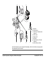
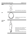
Reflector
MPR122, 360° Reflector PRO, for machine automation.
GNSS
The MNA1202 GG antenna mounted on the secondary
mast of the machine.
TCPS27S Radio
Modems
Except North Americas, TCPS27S radio modems with ITT
Cannon connectors are used on the machine, and
communicate with the TPS1200+ Radio Handle mounted
onto the instrument.
For further information refer to the TCPS27 user manual.
GNSS sensor (GPS /
GLONASS)
MEM
PWR
TRK
ME
PW M
R
TRK
The GNSS option uses the MNS1230 machine navigation
sensor (GNSS) or the PowerBox (GNSS) with power
protection and mil-connectors.
For further information refer to the Leica MNS1200 user
manual or the Leica GNSS Machine Positioning user
manual.
Slope sensor
One dual axis slope sensor with a CAN interface is used.
Mounted in the middle of the machine at the rotation
point.
For further information refer to the Dual Slope user
manual.
Machine Computer
The MPC1310 is a ruggedised computer with Windows
XP Embedded, touchscreen, milspec connectors for
power, CAN, four serial (RS232) and USB interfaces.
Bracket to mount Machine Computer for easy installation and removal at the end of the day, a power supply
for office preparation, a carry-case and a USB CF-Card
adapter are all supplied as part of the MPC1310 package.
For further information refer to the MPC1310 user
manual.
System Components, Diagrams, Software Description
PaveSmart 3D UM 67
System Components, Diagrams, Software Description
PaveSmart 3D UM 68
Total Station(s)
Further Hardware
PWR
BT
TRK
ON
OFF
The system supports TPS1200+ Total Stations with the
OnBoard software application MGuide and it supports
the Leica PowerTracker instruments. The radio modem is
optionally integrated into the handle of the instrument.
For further information refer to the TPS1200+ user
manual or the PowerTracker user manual.
For further details on each component listed below, refer to the technical reference manual
and/or the component specific manuals.
3.2
System Wiring Diagrams
General information
The system wiring is dependent on the purchased / installed solution. The main installation
is identical, only the serial port sensor combination may vary depending on the sensor
equipment used. It is possible to attach up to 4 Total Stations and a GNSS sensor.
)
•
•
•
•
The MPC1310 must be mounted with the bracket supplied. The rear of the MPC1310
should be free from obstructions to allow sufficient cooling.
Mast(s) must be fixed firmly to the frame of the machine so minimum vibration is experienced.
Slope sensors must be mounted at the rotating point of the machine with the arrow
facing forward direction of travel.
Use the machine-manufacturer-supplied slope sensor mounting bracket wherever possible.
Where applicable: Alternatively to the TCPS27S rugedised radio modems, approved 3rd
party radio modems, such as Freewave, with appropriate cables can be used. Refer to
the Leica PaveSmart 3D Technical Reference Manual for machine specific details.
System Components, Diagrams, Software Description
PaveSmart 3D UM 69
System Components, Diagrams, Software Description
1-Prism solution
)
PaveSmart 3D UM 70
The one prism solution uses one TPS instrument for continuous tracking of the machine. A
second optional TPS instrument can be attached for leapfrogging and/or as-built measurements.
This can only be used with "one track steer" machines, such as Gomaco GT3200
series curb & gutter/offset paver, Gomaco PS2600 placer-spreaders, or PowerCurber
5700 series offset pavers, or where the steer function rear track(s) of an all-tracksteer machine are disabled (ensure to verify track angle is perfectly parallel to the
machine travel direction otherwise poor paving quality will result!).
a
b
c
a) Mast Position
Primary reflector
(B1)
b) Direction of travel
c) TPS Instrument
System components for MOBA-matic or Wirtgen DLS/LevelPro equipped Road Paver
and Milling machine:
a
b
l
c
m
d
e
n
f
f
g
g
h
i
j
k
System Components, Diagrams, Software Description
o
p
i
j
q
r
a) MPC1310
b) TCPS27S radio modems
c) PWM cables for serial connection(s) to TCPS27S
d) Alarm box
e) CAN cable to alarm box
f) MOBA-matic controller
g) Cable MOBA-matic controller
to junctionbox
h) Junctionbox Left
i) Dual-axis slope sensor
j) CAN cable slope sensor to
junctionbox
k) Slope sensor CAN
l) H-cable Power / CAN connection, machine specific
m) PWM cable for serial connection (COM3) to TCPS27S
n) Road Paver machine
o) Junctionbox Right
p) CAN Cable to connect junctionbox
q) Y-CAN cable to connect slope
sensor
r) Connector cable to machine,
machine-specific
PaveSmart 3D UM 71
System Components, Diagrams, Software Description
PaveSmart 3D UM 72
System components for Curb and Gutter/Offset paving machine:
a
b
g
c
d
e
h
f
i
a) MPC1310
b) TCPS27S radio modems
c) PWM cables for serial connection(s) to TCPS27S
d) PWM cable for serial connection (COM3) to TCPS27S
e) Curb and Gutter machine
f) Dual-axis slope sensor
g) H-cable Power / CAN connection, machine specific
h) Cable to machine, usually
supplied by machine manufacturer as part of 3D Kit
i) CAN cable slope sensor to
MPC1310
1-GNSS solution
The one GNSS solution uses one GNSS sensor for continuous tracking of the machine. An
optional TPS instrument can be attached for as-built measurements:
a
b
c
a) GNSS reference station
b) Direction of travel
c) Mast Position GNSS antenna Primary (B1)
System Components, Diagrams, Software Description
PaveSmart 3D UM 73
System Components, Diagrams, Software Description
PaveSmart 3D UM 74
System components for Wirtgen- or MOBA equipped milling machines:
a
b
k
c
d
l
e
f
g
m
h
i
j
n
o
p
q
a) MPC1310
b) TCPS27S radio modems
c) PWM cable for serial connection to TCPS27S
d) PWM cable for serial connection (COM3) to TCPS27S
e) Alarm box
f) CAN cable to alarm box
g) Cable MPC1310 to PowerBox
h) Cable PowerBox to machine
battery
i) SATELLine or Freewave radio
j) PowerBox GNSS sensor
k) H-cable Power / CAN connection, machine specific
l) Cable to machine, usually
supplied by machine manufacturer as part of 3D Kit
m) Milling machine
n) GNSS antenna
o) Antenna cable
p) CAN cable to connect slope
sensor
q) Dual-axis slope sensor
The controls are normally an integral part of the machine. The components are connected
directly to the standard (or optional) machine junctionbox and communication cables are
connected via the machine's own CAN bus.
2-Prism solution
The two prism solution uses two TPS instruments for continuous tracking of the machine. A
third optional TPS instrument can be attached for leapfrogging and/or as-built measurements.
For tracked Voegele roadpavers equipped with the latest NaviTronic system, this
arrangement can also regulate automatic steering direction of the machine. Please
refer to Voegele for details of NaviTronic autosteer-compatible machines.
a
b c
f
System Components, Diagrams, Software Description
d
e
a) Mast position
Primary reflector
(B1)
b) TPS Instrument
c) Mast position
Secondary reflector
(B2)
d) Direction of travel
e) TPS Instrument
f) Spare TPS (for asbuilt and leapfrog)
PaveSmart 3D UM 75
System Components, Diagrams, Software Description
PaveSmart 3D UM 76
System components for Vögele Road Paver machine:
a
b
e
c
d
f
g
a) MPC1310
b) TCPS27S radio modems
c) PWM cables for serial connection(s) to TCPS27S
d) PWM cable for serial connection (COM3) to TCPS27S
e) H-cable Power / CAN connection, machine specific
f) Machine connection cable
g) Road Paver machine
GNSS-Prism solution
The GNSS-Prism solution uses one TPS instrument and a GNSS (GPS/GLONASS) sensor for
continuous tracking of the machine. A second optional TPS instrument can be attached for
leapfrogging and/or as-built measurements:
a
b
f
System Components, Diagrams, Software Description
c
d
e
a) Mast Position Primary
Reflector (B1)
b) Mast Position GNSS antenna
Secondary (B2)
c) Direction of travel
d) GNSS reference station
e) TPS Instrument (Primary)
f) Spare TPS (for as-built and
leapfrog)
PaveSmart 3D UM 77
System Components, Diagrams, Software Description
PaveSmart 3D UM 78
System components for Curb and Gutter machine:
a
b
c
d
e
f
g
h
i
j
a) MPC1310
b) TCPS27S radio modems
c) PWM cable for serial connection to TCPS27S
d) PWM cable for serial connection (COM3) to TCPS27S
k e) CAN cable to connect slope
sensor
f) Dual-axis slope sensor
g) Cable MPC1310 to PowerBox
h) Cable PowerBox to machine
l
battery
i) SATELLine or Freewave radio
j) PowerBox GNSS sensor
k) H-cable Power / CAN connecm
tion, machine specific
l) Cable to machine, usually
supplied by machine manufacturer as part of 3D Kit
n m) Curb and Gutter machine
o n) GNSS antenna
o) Antenna cable
p
p) CAN cable to connect slope
sensor
q
q) Dual-axis slope sensor
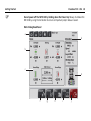
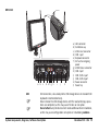
MPC1310
i Fi
W
l
a)
b)
c)
d)
e)
f)
KEYBOARD USB B
USB A
LAN
COM 1
a
USB
)
)
b
c
FUSE 2A
COM 3/CAN 1 COM 4/CAN 2
POWER
COM 2
d e f g h
i
j
k
g)
h)
i)
j)
k)
l)
LAN connector
Ventilation cap
USB A Host connector
COM 1 port
Keyboard connector
2A fuse for outgoing
power
USB B Device connector
COM 2 port
COM 3/CAN 1 port
COM 4/CAN 2 port
Power connector
Power key
USB connection, Leica Geosystems USB storage device or standard USB
keyboards recommended only.
Never remove the USB storage device until file read/write/copy operations are completed, as this may cause file loss or corruption.
Do not attach any USB device which needs additional driver installation,
as this may cause configuration corruption or installation problems.
System Components, Diagrams, Software Description
PaveSmart 3D UM 79
System Components, Diagrams, Software Description
COM 1, 2, 3, 4
CAN 1, 2
POWER
Power key
Caution
KEYBOARD
PaveSmart 3D UM 80
Serial Ports for Radio Modem connection to Total Station and connection
to GNSS sensor. Power output voltage: regulated +13.6 V
CAN bus connection.
Power in, 10-36 volt DC, reverse polarity protected.
To turn On and Off the Machine Computer.
Never turn Off the Machine Computer without shutting down all running
applications. This could result in unexpected data loss!
Precautions:
Black screen must be displayed after pressing the Shutdown button in
Leica PaveSmart 3D software before switching the power off to the
MPC1310.
Permits connection of external keyboards with compatible LEMO connectors. Contact Leica Geosystems for further information.
3.3
Software Description
General
PaveSmart 3D is a machine control application for paving and milling machines. The system
software controls the steer-, elevation- and slope control loop of the machine.
The 3D design model is loaded onto the Machine Computer. The software compares the
actual position of the machine with the design. The actual position is calculated with
attached System 1200 tracking data and the slope sensor mounted onto the machine.
The calculated deviations are then according to the control parameters transformed into
variables for the hydraulic, which are sent via CAN bus to the machine controller. Therefore
the sensitivities on the machine controller have to be deactivated or set to zero unless
advised otherwise by a Leica Geosystems or machine manufacturer authorised support engineer.
Menu Structure
Password for configuration level
Default Config password = 007
System Components, Diagrams, Software Description
PaveSmart 3D UM 81
System Components, Diagrams, Software Description
PaveSmart 3D UM 82
Menu in configuration level; all buttons accessible
Work screen
Dialogs
Refer to "2.2 Operating the MPC1310 Machine Computer" for more information about the
Work and the Menu dialog.
System Components, Diagrams, Software Description
PaveSmart 3D UM 83
Troubleshooting
4
Troubleshooting
PaveSmart 3D UM 84
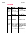
Troubleshooting
Problem
Possible cause(s)
Suggested remedies
Computer does
not boot or start
up or keeps
rebooting
Inadequate or missing power
supply
Power regulator failed
Reversed power supply polarity
Check machine power supply, fuses
and voltage regulator
Check connections to the MPC1310
Damaged Machine Computer
Contact Leica Geosystems
Damaged power cable
Check all cables for damage
Leica PaveSmart Auto-Start is not enabled
3D does not start Configuration corrupted
Restore Auto-Start link
Copy backup from USB storage
device
Configuration is
Configuration corrupted
lost or strange
behaviour of Leica
PaveSmart 3D
Restore back up in the Projects
menu
Total Station fails Communication parameters on
to initialise
instrument are not set correctly
Baud rate is not identical on
instrument and in the software
Choose appropriate Conig Set (TCRP
RCS-RH1200 or TCRP RCS-TCPS27)
Green LED's on a radio modem pair
need to be On
Radio modems have not the same Configure radio modems to the
Link / baud rate configuration
same the same Link / baud rate
configuration
•
Low battery at instrument
•
Instrument is in a configuration
menu or in As-Built menu
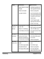
Problem
Possible cause(s)
Suggested remedies
•
Radio interference or cabling
damaged
•
Install MGuide application and
choose appropriate Config Set
•
MGuide is not installed
•
Contact Leica Geosystems
•
Low power at machine
•
Ensure the radio handle is on the
correct way with the lights facing
the operator and the antenna
facing the paver.
•
Turn on the paver as power
supply may not be sufficient if
the paver is not running
Total Station does •
not react on
commands
•
•
MGuide application is in config- •
uration mode
•
MGuide is in As-Built dialog
Auto-Shutdown at instrument •
Change to MGuide main menu
Solve instrument error message
(refer to TPS1200+ manual)
Unplug power cable and restart
instrument
GNSS sensor is
not initialised
Communication parameters on •
sensor are not set correct
•
Baud rate is not identical on
instrument and in the software •
Set correct Config Set on sensor
Check communication parameters on sensor
Contact Leica Geosystems
•
•
Wrong transformation file
loaded
No reference signal available
Check transformation file on
sensor
Check reference signal
•
•
Bad satellite distribution
Not enough satellite available
•
•
•
•
GNSS position
accuracy is bad
Troubleshooting
•
•
Contact Leica Geosystems
Check radio configuration
between MNS and base station
PaveSmart 3D UM 85
Troubleshooting
PaveSmart 3D UM 86
Problem
Possible cause(s)
Suggested remedies
Leica PaveSmart •
3D is not reacting •
to user input via
touchscreen or
keyboard
Flash disk is full
System has crashed
Strange behaviour •
- machine lifts
legs incorrectly
•
and/or drives off
steering line
•
Slope sensor incorrectly orien- •
tated/adjusted
•
Total Station incorrectly
oriented
Machine not in Leica/Automatic
•
mode
Hydraulic tuning not appropriate
•
Strange steering
behaviour when
Leica PaveSmart
3D is sending
correct values to
machine
•
Nervous overreactive steering
behaviour
•
•
•
•
Steering in Manual Mode on
machine panel
Tracks/feedback pots incorrectly adjusted
•
Steering Sensitivity too high
•
•
•
Remove unnecessary Jobs or log
files
Reboot computer
Check installation and readjust
slope sensor as required
Perform a Tiepoint check to
verify Total Station orientation
(if necessary new Resection)
Check Machine Controller all
control loops must be in automatic.
Set Steer for each Leg into Automatic
Check and readjust machine
steering as required
Set Steer Sensitivity to Minimum
on machine panel
Adjust steer tuning parameters
Problem
Possible cause(s)
•
System starts
Tracking, but no
deviations are
•
displayed on
screen and dashboard blinks
•
•
System has detected a problem
and stops for safty
Wrong prism targeted or wrong
moving prism as-signed to
Total Station
Wrong reference line of Job
activated in Design dialog
Machine is outside the limits of
the project
Suggested remedies
•
•
•
•
•
Dashboard blinks •
red continuously
Tolerances exceeded
•
Press dashboard button and
check error message
Machine stops, all •
deviations are
shown as "-" or
•
error
Wrong Job or reference line is
loaded in the Job dialog
Machine is out of project
•
Check in the Job dialogue to see
which design is selected
Check the assigned reference
line
Check Offsets
•
•
System is tracking •
OK but machine
does not move
Stop rule is active and machine •
is outside of the defined tolerance range
•
•
Troubleshooting
Check dashboard message
Target correct prism and reassign prism to Total Station (B#,
only with 2 prism solution)
Perform a Tiepoint check to
verify Total Station orientation
(if necessary new Resection)
Check loaded Job and assigned
reference line
Drive the machine within the
design extents manually
Deactivate Stop rule and drive
machine to design position
As a short term measure, deviation can be reduced with the
offset and the machine driven to
the design position
Care must be taken to re set
stop rules
PaveSmart 3D UM 87
Troubleshooting
PaveSmart 3D UM 88
Problem
Possible cause(s)
Suggested remedies
Position offsets
are wrong
•
•
•
Wrong Job or reference line is
chosen
Offsets are wrong
Slopes and eleva- •
tions become
gradually imprecise while paving
•
After paving for a long period
the geometry of the machine
may change (mold settles,
wear and tear, vibration etc.)
Instrument adjustment drift
•
No log files saved •
•
Disk space full
Log files have not been properly activated
•
Strange behaviour •
- wrong machine
pa-rameters
saved
System crashed (power supply) •
Close system. Restore the
configuration settings.
Machine start to
undulate during
paving
Too much head of concrete or •
sub grade in front of machine
Hydraulic lift pressure incorrect
Reduce head of material, refer to
machine manual, check hydraulic
system
•
•
•
•
•
Check the chosen Job in the Job
dialog
Check the chosen reference line
Check the steering offsets
Check and readjust mold slope
sensor regularly
Readjust Total Station(s)
Delete unnecessary data in the
Manage dialog
Problem
Possible cause(s)
Machine height is •
controlled in
wrong direction
•
e.g. correction up
-> machine goes
down and vice
versa
Hydraulic tuning parameters
incorrect
Slope sensor mounted in the
wrong direction
•
•
Contact Leica Geosystems
Reset the default tuning parameter in elevation and Steer.
Retune machine before paving
TPS or GNSS
Battery does not
hold charge
Battery has previously only
been partially discharged
before recharging
Suffering from memory effect
•
Refer to the charger manual for
discharge/recharge cycle instructions
•
•
Troubleshooting
Suggested remedies
PaveSmart 3D UM 89
Care and Transport
PaveSmart 3D UM 90
5
Care and Transport
5.1
Transport
Transport in the field
When transporting the equipment in the field, always make sure that you carry the product
in its original transport container.
Transport in a road
vehicle
Never carry the product loose in a road vehicle, as it can be affected by shock and vibration.
Always carry the product in its transport container and secure it.
Shipping
When transporting the product by rail, air or sea, always use the complete original Leica
Geosystems packaging, transport container and cardboard box, or its equivalent, to protect
against shock and vibration.
5.2
Storage
Product
Respect the temperature limits when storing the equipment, particularly in summer if the
equipment is inside a vehicle. Refer to the "7 Technical Data" chapter for information about
temperate limits for each component. This information may be contained in the component
specific manual.
It is always recommended to store the MPC1310 and total stations in their supplied cases,
protected against influences of the weather during longer working breaks (e.g. overnight,
at weekends).
5.3
Cleaning and Drying
General
Use only a clean, soft, lint-free cloth for cleaning. If necessary, moisten the cloth with water
or pure alcohol.
Do not use other liquids; these may attack the polymer components.
Damp products
Dry the product, the transport container, the foam inserts and the accessories at a temperature not greater than 40°C / 108°F and clean them. Do not repack until everything is
completely dry.
Cables and plugs
Keep plugs clean and dry. Blow away any dirt lodged in the plugs of the connecting cables.
Connectors with dust
caps
Wet connectors must be completely dry before attaching the dust cap.
5.4
Maintenance
Control measurements
During paving or trimming, control measurements must be made regularly to determine
possible changes in the machine geometry or in the sensors. Paving or trimming accuracy is
influenced by jobsite conditions such as temperature, visibility and material consistency and
can be adjusted through offsets.
Care and Transport
PaveSmart 3D UM 91
Safety Directions
PaveSmart 3D UM 92
6
Safety Directions
6.1
General
Description
The following directions should enable the person responsible for the product, and the
person who actually uses the equipment, to anticipate and avoid operational hazards.
The person responsible for the product must ensure that all users understand these directions and adhere to them.
6.2
Intended Use
Permitted use
•
•
•
•
•
Adverse use
•
•
•
•
•
•
•
•
Guidance of construction machines by means of the position signals (The subordinated
machine control system has to provide all safety functions. This machine control system
has to be checked prior to placing it into operation).
Contact-free determination of the position of construction machines
Computation and evaluation of data by means of software
Visualisation of the data
Recording of data
Use of the product without instruction.
Use outside of the intended limits.
Disabling safety systems.
Removal of hazard notices.
Opening the product using tools, for example screwdriver, unless this is specifically
permitted for certain functions.
Modification or conversion of the product.
Use after misappropriation.
Use of products with obviously recognizable damages or defects.
•
•
•
Warning
Use with accessories from other manufacturers without the prior explicit approval of
Leica Geosystems.
Inadequate safeguards at the surveying/working site, for example when measuring on
roads.
Controlling of machines, moving objects or similar monitoring application without additional control- and safety installations.
Adverse use can lead to injury, malfunction and damage. It is the task of the person responsible for the equipment to inform the user about hazards and how to counteract them. The
product is not to be operated until the user has been instructed on how to work with it.
6.3
Limits of Use
Environment
Suitable for use in an atmosphere appropriate for permanent human habitation: not suitable
for use in aggressive or explosive environments.
Danger
Safety Directions
Local safety authorities and safety experts must be contacted before working in hazardous
areas, or in close proximity to electrical installations or similar situations by the person in
charge of the product.
PaveSmart 3D UM 93
Safety Directions
PaveSmart 3D UM 94
6.4
Responsibilities
Manufacturer of the
product
Leica Geosystems AG, CH-9435 Heerbrugg, hereinafter referred to as Leica Geosystems, is
responsible for supplying the product, including the user manual and original accessories, in
a completely safe condition.
Manufacturers of non
Leica Geosystems
accessories
The manufacturers of non Leica Geosystems accessories for the product are responsible for
developing, implementing and communicating safety concepts for their products, and are
also responsible for the effectiveness of those safety concepts in combination with the
Leica Geosystems product.
Person in charge of the
product
The person in charge of the product has the following duties:
• To understand the safety instructions on the product and the instructions in the User
Manual.
• To be familiar with local safety regulations relating to accident prevention.
• To inform Leica Geosystems immediately if the equipment becomes unsafe.
• To ensure that the national laws, regulations and conditions for the operation of radio
transmitters are respected.
Warning
The person responsible for the product must ensure that it is used in accordance with the
instructions. This person is also accountable for the training and the deployment of
personnel who use the product and for the safety of the equipment in use.
This product may be installed on building machinery only by an appropriately trained and
qualified specialist.
Unauthorised modification of machines by mounting the product may alter the function and
safety of the machine.
Precautions:
Follow the instructions of the machine manufacturer. If no appropriate instruction is available, ask machine manufacturer for instructions before mounting the product.
6.5
Software Licence Agreement
International Warranty
The International Warranty can be downloaded from the Leica Geosystems home page at
http://www.leica-geosystems.com/internationalwarranty or received from your Leica
Geosystems dealer.
Software Licence
Agreement
This product contains software that is preinstalled on the product, or that is supplied to you
on a data carrier medium, or that can be downloaded by you online pursuant to prior authorisation from Leica Geosystems. Such software is protected by copyright and other laws and
its use is defined and regulated by the Leica Geosystems Software Licence Agreement,
which covers aspects such as, but not limited to, Scope of the Licence, Warranty, Intellectual
Property Rights, Limitation of Liability, Exclusion of other Assurances, Governing Law and
Place of Jurisdiction. Please make sure, that at any time you fully comply with the terms and
conditions of the Leica Geosystems Software Licence Agreement.
Such agreement is provided together with all products and can also be found at the Leica
Geosystems home page at http://www.leica-geosystems.com/swlicense or your Leica
Geosystems dealer.
You must not install or use the software unless you have read and accepted the terms and
conditions of the Leica Geosystems Software Licence Agreement. Installation or use of the
software or any part thereof, is deemed to be an acceptance of all the terms and conditions
of such licence agreement. If you do not agree to all or some of the terms of such licence
agreement, you may not download, install or use the software and you must return the
unused software together with its accompanying documentation and the purchase receipt
to the dealer from whom you purchased the product within ten (10) days of purchase to
obtain a full refund of the purchase price.
Safety Directions
PaveSmart 3D UM 95
Safety Directions
PaveSmart 3D UM 96
6.6
Microsoft End User License Agreement ("EULA")
END USER LICENSE
AGREEMENT FOR
MICROSOFT EMBEDDED
SYSTEMS
•
•
•
You have acquired a device ("DEVICE") that includes software licensed by Leica Geosystems from Microsoft Licensing, GP or its affiliates ("MS"). Those installed software products of MS origin, as well as associated media, printed materials, and "online" or electronic documentation ("SOFTWARE") are protected by international intellectual property
laws and treaties. The SOFTWARE is licensed, not sold. All rights reserved.
IF YOU DO NOT AGREE TO THIS END USER LICENSE AGREEMENT ("EULA"), DO NOT USE THE
DEVICE OR COPY THE SOFTWARE. INSTEAD, PROMPTLY CONTACT LEICA GEOSYSTEMS FOR
INSTRUCTIONS ON RETURN OF THE UNUSED DEVICE(S) FOR A REFUND. ANY USE OF THE
SOFTWARE, INCLUDING BUT NOT LIMITED TO USE ON THE DEVICE, WILL CONSTITUTE YOUR AGREEMENT TO THIS EULA (OR RATIFICATION OF ANY PREVIOUS
CONSENT).
GRANT OF SOFTWARE LICENSE. This EULA grants you the following license:
• You may use the SOFTWARE only on the DEVICE.
• NOT FAULT TOLERANT. THE SOFTWARE IS NOT FAULT TOLERANT. LEICA GEOSYSTEMS
HAS INDEPENDENTLY DETERMINED HOW TO USE THE SOFTWARE IN THE DEVICE, AND
MS HAS RELIED UPON LEICA GEOSYSTEMS TO CONDUCT SUFFICIENT TESTING TO DETERMINE THAT THE SOFTWARE IS SUITABLE FOR SUCH USE.
• NO WARRANTIES FOR THE SOFTWARE. THE SOFTWARE is provided "AS IS" and with
all faults. THE ENTIRE RISK AS TO SATISFACTORY QUALITY, PERFORMANCE, ACCURACY,
AND EFFORT (INCLUDING LACK OF NEGLICENCE) IS WITH YOU. ALSO, THERE IS NO
WARRANTY AGAINST INTERFERENCE WITH YOUR ENJOYMENT OF THE SOFTWARE OR
AGAINST INFRINGEMENT. IF YOU HAVE RECEIVED ANY WARRANTIES REGARDING
THE DEVICE OR THE SOFTWARE, THOUSE WARRANTIES DO NOT ORIGINATE
FROM, AND ARE NOT BINDING ON, MS.
• No Liability for Certain Damages. EXCEPT AS PROHIBITED BY LAW, MS SHALL HAVE
NO LIABILITY FOR ANY INDIRECT, SPECIAL, CONSEQUENTIAL OR INCIDENTAL
DAMAGES ARISING FROM OR IN CONNECTION WITH THE USE OR PERFORMANCE
OF THE SOFTWARE. THIS LIMITATION SHALL APPLY EVEN IF ANY REMEDY FAILS
OF ITS ESSENTIAL PURPOSE, IN NO EVENT SHALL MS BE LIABILE FOR ANY
AMOUNT IN EXCESS OF U.S. TWO HUNDRED FIFTY DOLLARS (U.S.$250.00).
• Limitations on Reverse Engineering, Decompilation, and Disassembly. You may
not reverse engineer, decompile, or disassemble the SOFTWARE, except and only to
the extent that such activity is expressly permitted by applicable law notwithstanding
this limitation.
• SOFTWARE TRANSFER ALLOWED BUT WITH RESTRICTIONS. You may permanently
transfer rights under this EULA only as part of a permanent sale or transfer of the
Device, and only if the recipient agrees to this EULA. If the SOFTWARE is an upgrade,
any transfer must also include all prior versions of the SOFTWARE.
• EXPORT RESTRICTIONS. You acknowledge that SOFTWARE is subject to U.S. export
jurisdiction. You agree to comply with all applicable international and national laws
that apply to the SOFTWARE, including the U.S. Export Administration Regulations, as
well as end-user, end-use and destination restrictions issued by U.S. and other
governments. For additional information see http://www.microsoft.com/exporting/.
Safety Directions
PaveSmart 3D UM 97
Safety Directions
PRODUCT SPECIFIC
TERMS
PaveSmart 3D UM 98
•
RESTRICTED FUNCTIONALITY. You are licensed to use the SOFTWARE to provide only
the limited functionality (specific tasks or processes) for which the DEVICE has been
designed and marketed by Leica Geosystems. This license specifically prohibits any other
use of the SOFTWARE programs or functions, or inclusion of additional software
programs or functions that do not directly support the limited functionality on the
DEVICE.
a) Notwithstanding the foregoing, you may install or enable on the DEVICE systems utilities,
resource management or similar software (including without limitation anti-virus software)
(collectively, "Support Software") solely for the purpose of administration, performance
enhancement and/or preventive maintenance of the DEVICE. You acknowledge and agree
that with respect to any Support Software: (i) the Support Software may not be compatible with the SOFTWARE installed on your DEVICE; (ii) no warranty is provided by MS, Microsoft Corporation or their affiliates for any Support Software that you may install on your
DEVICE; and (iii) neither MS, Microsoft Corporation nor their affiliates is responsible for
technical support of any Support Software you may install on your DEVICE. Please contact
Leica Geosystems if you have any questions regarding any Support Software that you are
considering installing on your DEVICE.
b) The DEVICE may use terminal services protocols (such as Remote Desktop Protocol,
Remote Assistance or Independent Computer Architecture) to connect or access Applications (as defined below) running on a server; however, these Applications may not run
locally on the DEVICE. For purposes of this provision, "Applications" mean software that
provides any of the following functionality: consumer or business tasks or processes
performed by a computer or computing device, including email, word processing, spreadsheets, database, scheduling, or personal finance.
•
DEVICE CONNECTIONS. The SOFTWARE may not be used by more than two (2) processors at any one time on the DEVICE. You may permit a maximum of ten (10) computers
or other electronic devices to connect via Server Message Block (SMB) to the DEVICE to
utilize one or more of the following services of the SOFTWARE: (a) file services, print
services, (b) Internet information services and/or (c) remote access (including connection
sharing). The ten connection maximum includes any indirect connections made through
"multiplexing" or other software or hardware which pools or aggregates connections.
This ten connection maximum does not apply to other uses of the SOFTWARE. Unlimited
simultaneous inbound connections are permitted via TCP/IP.
Safety Directions
•
CLIENT ACCESS LICENSES. If you use the DEVICE to access or utilize the services or functionality of Microsoft Windows Server products (such as Microsoft Windows Server
2003), or use the DEVICE to permit workstation or computing devices to access or utilize
the services or functionality of Microsoft Windows Server products, you may be required
to obtain a Client Access License for the DEVICE and/or each such workstation or
computing device. Please refer to the end user license agreement for your Microsoft
Windows Server product for additional information.
•
REMOTE DESKTOP FEATURES/NETMEETING/REMOTE ASSISTANCE. The SOFTWARE
may contain NetMeeting, Remote Assistance, and Remote Desktop technologies that
enable the SOFTWARE or other applications installed on the DEVICE to be used remotely
between two or more computing devices, even if the SOFTWARE or application is installed
on only one DEVICE. You may use NetMeeting, Remote Assistance, and Remote Desktop
with all Microsoft products; provided however, use of these technologies with certain
Microsoft products may require an additional license. For both Microsoft products and
non-Microsoft products, you should consult the license agreement accompanying the
applicable product or contact the applicable licensor to determine whether use of
NetMeeting, Remote Assistance, or Remote Desktop is permitted without an additional
license.
•
REMOTE BOOT FEATURE. Your DEVICE may be enabled with a Remote Boot feature
which includes the Remote Boot Installation Service tool. You may (i) use the Remote
Boot Installation Service tool to install one (1) copy of the SOFTWARE onto your server
solely for the purpose of deploying the SOFTWARE to one or more DEVICEs on which you
PaveSmart 3D UM 99
Safety Directions
PaveSmart 3D UM 100
are licensed to run the SOFTWARE (i.e. DEVICEs to which the appropriate Certificate of
Authenticity is affixed) ); (ii) download the SOFTWARE over your internal network only
onto such licensed DEVICEs; and (iii) use the Remote Boot Installation Service only for
deployment of the SOFTWARE to licensed DEVICEs as part of the Remote Boot process.
Please refer to the DEVICE documentation, if provided with your DEVICE, or contact Leica
Geosystems for additional information.
•
AUTOMATIC INTERNET-BASED SERVICES. The SOFTWARE features described below are
enabled by default to connect via the Internet to Microsoft computer systems automatically, without separate notice to you. You consent to the operation of these features,
unless you choose to switch them off or not use them. Microsoft does not use these
features to collect any information that will be used to identify you or contact you. For
more information about these features, please see the privacy statement at
http://go.microsoft.com/fwlink/?LinkId=25243
• Web Content Features. Under the SOFTWARE's default configuration, if you are
connected to the Internet, several features of the SOFTWARE are enabled by default
to retrieve content from Microsoft computer systems and display it to you. When you
activate such a feature, it uses standard Internet protocols, which transmit the type
of operating system, browser and language code of your DEVICE to the Microsoft
computer system so that the content can be viewed properly from your DEVICE. These
features only operate when you activate them, and you may choose to switch them
off or not use them. Examples of these features include Windows Catalog, Search
Assistant, and the Headlines and Search features of Help and Support Center.
• Digital Certificates. The SOFTWARE uses digital certificates based on the x.509
standard. These digital certificates confirm the identity of Internet users sending x.509
standard encrypted information. The SOFTWARE retrieves certificates and updates
certificate revocation lists. These security features operate only when you use the
Internet.
• Auto Root Update. The Auto Root Update feature updates the list of trusted certificate authorities. You can switch off the Auto Root Update feature.
• Windows Media Player. Some features of Windows Media Player automatically
contact Microsoft computer systems if you use Windows Media Player or specific
features of it: features that (A) check for new codecs if your DEVICE does not have the
correct ones for content you attempt to play (this feature may be switched off), and
(B) check for new versions of Windows Media Player (this feature will operate only
when you are using Windows Media Player).
• Windows Media Digital Rights Management. Content providers are using the digital
rights management technology for Windows Media contained in this SOFTWARE ("WMDRM") to protect the integrity of their content ("Secure Content") so that their intellectual property, including copyright, in such content is not misappropriated. Portions
of this SOFTWARE and third party applications such as media players use WM-DRM to
play Secure Content ("WM-DRM Software"). If the WM-DRM Software's security has
been compromised, owners of Secure Content ("Secure Content Owners") may
request that Microsoft revoke the WM-DRM Software's right to copy, display and/or
play Secure Content. Revocation does not alter the WM-DRM Software's ability to play
unprotected content. A list of revoked WM-DRM Software is sent to your DEVICE whenever you download a license for Secure Content from the Internet. Microsoft may, in
conjunction with such license, also download revocation lists onto your DEVICE on
behalf of Secure Content Owners. Secure Content Owners may also require you to
upgrade some of the WM-DRM components in this SOFTWARE ("WMDRM Upgrades")
before accessing their content. When you attempt to play such content, WM-DRM
Software built by Microsoft will notify you that a WM-DRM Upgrade is required and
then ask for your consent before the WM-DRM Upgrade is downloaded. WMDRM Software built by third parties may do the same. If you decline the upgrade, you will not
be able to access content that requires the WM-DRM Upgrade; however, you will still
be able to access unprotected content and Secure Content that does not require the
upgrade. WM-DRM features that access the Internet, such as acquiring new licenses
Safety Directions
PaveSmart 3D UM 101
Safety Directions
PaveSmart 3D UM 102
and/or performing a required WM-DRM Upgrade, can be switched off. When these
features are switched off, you will still be able to play Secure Content if you have a
valid license for such content already stored on your DEVICE.
•
WINDOWS UPDATE AGENT (ALSO KNOWN AS SOFTWARE UPDATE SERVICES). If the
SOFTWARE includes Windows Update Agent ("WUA") (also known as Software Update
Services) functionality that may enable your DEVICE to connect to and access updates
("Windows Updates") from a server installed with the required server component then
the following conditions apply:
• Without limiting any other disclaimer in this EULA, or any EULA accompanying a
Windows Update, you acknowledge and agree that no warranty is provided by MS,
Microsoft Corporation or their affiliates with respect to any Windows Update that you
install or attempt to install on your DEVICE;
• In addition, you acknowledge and accept that (i) Windows Updates may not be necessary or suitable for installation on or use with your DEVICE or the SOFTWARE, and (ii)
if installed or attempted to be installed on your DEVICE, Windows Updates may not
function on the DEVICE or may malfunction and/or cause harm to the DEVICE, to operators of the DEVICE or to other persons or property. If you connect to a server that
installs a Windows Update, you agree that you assume all risk and liability with regard
to any Windows Update that you install or attempt to install on your DEVICE using
functionality provided by SOFTWARE. You further agree that neither MS, Microsoft
Corporation nor their affiliates have any liability to you with respect to any Windows
Update that you install or attempt to install on your DEVICE; and
• Leica Geosystems is solely responsible for providing technical support, if any, to you
in connection with your installation of Windows Updates installed on your DEVICE
using WUA functionality provided by the SOFTWARE. Please contact Leica Geosystems
if you have any questions regarding any Windows Update that you are considering
installing on your DEVICE or otherwise regarding the WUA functionality.
NOTICES REGARDING THE MPEG-4 VISUAL STANDARD. The SOFTWARE may include
MPEG-4 visual decoding technology. This technology is a format for data compression of
video information. For this technology, MPEG LA, L.L.C. requires this notice:
"USE OF THIS PRODUCT IN ANY MANNER THAT COMPLIES WITH THE MPEG-4
VISUAL STANDARD IS PROHIBITED, EXCEPT FOR USE DIRECTLY RELATED TO (A)
DATA OR INFORMATION (i) GENERATED BY AND OBTAINED WITHOUT CHARGE
FROM A CONSUMER NOT THEREBY ENGAGED IN A BUSINESS ENTERPRISE, AND
(ii) FOR PERSONAL USE ONLY; AND (B) OTHER USES SPECIFICALLY AND SEPARATELY LICENSED BY MPEG LA, L.L.C.
If you have questions regarding this notice, please contact MPEG LA, L.L.C., 250 Steele
Street, Suite 300, Denver, Colorado 80206; Telephone 303 331.1880; FAX 303
331.1879; www.mpegla.com."
GENERAL TERMS
•
•
Safety Directions
PRODUCT SUPPORT. Product support for the SOFTWARE is not provided by MS, Microsoft Corporation or their affiliates. For product support, please refer to Leica Geosystems
support number provided in the documentation for the DEVICE. Should you have any
questions concerning this EULA, or if you desire to contact Leica Geosystems for any
other reason, please refer to the address provided in the documentation for the DEVICE.
END USER PROOF OF LICENSE. If you acquired the SOFTWARE installed on the DEVICE,
or on a compact disc or other media, a genuine Microsoft "Proof of License"/Certificate
of Authenticity label with a genuine copy of the SOFTWARE identifies a licensed copy of
the SOFTWARE. To be valid, the label must be affixed to the DEVICE, or appear on Leica
Geosystem's software packaging. If you receive the label separately other than from the
Leica Geosystems it is invalid. You should keep the label on the DEVICE or packaging to
prove that you are licensed to use the SOFTWARE. This End User License Agreement
("EULA") is valid and grants the end-user rights ONLY if the SOFTWARE is genuine and a
genuine Certificate of Authenticity for the SOFTWARE is included. For more information
on identifying whether your SOFTWARE is genuine, please see http://www.microsoft.com/piracy/howtotell.
PaveSmart 3D UM 103
Safety Directions
PaveSmart 3D UM 104
•
•
•
•
•
•
BACKUP COPY. You may make one (1) backup copy of the SOFTWARE. You may use this
backup copy solely for your archival purposes and to reinstall the SOFTWARE on the
DEVICE. Except as expressly provided in this EULA or by local law, you may not otherwise
make copies of the SOFTWARE, including the printed materials accompanying the SOFTWARE. You may not loan, rent, lend or otherwise transfer the backup copy to another
user.
RESTRICTED USE. The SOFTWARE is not designed or intended for use or resale in
hazardous environments requiring fail-safe performance, such as in the operation of
nuclear facilities, aircraft navigation or communication systems, air traffic control, or
other devices or systems in which a malfunction of the SOFTWARE would result in foreseeable risk of injury or death to the operator of the device or system, or to others.
NO RENTAL/COMMERCIAL HOSTING. You may not rent, lease, lend or provide commercial hosting services with the SOFTWARE to others.
SEPARATION OF COMPONENTS. The SOFTWARE is licensed as a single product. Its
component parts may not be separated for use on more than one device computer.
CONSENT TO USE OF DATA. You agree that MS, Microsoft Corporation and their affiliates may collect and use technical information gathered in any manner as part of product
support services related to the SOFTWARE. MS, Microsoft Corporation and their affiliates
may use this information solely to improve their products or to provide customized services or technologies to you. MS, Microsoft Corporation and their affiliates may disclose
this information to others, but not in a form that personally identifies you.
INTERNET GAMING/UPDATE FEATURES. If the SOFTWARE provides, and you choose to
utilize, the Internet gaming or update features within the SOFTWARE, it is necessary to
use certain computer system, hardware, and software information to implement the
features. By using these features, you explicitly authorise MS, Microsoft Corporation,
their affiliates and/or their designated agent to use this information solely to improve
their products or to provide customized services or technologies to you. MS, Microsoft
Corporation or their affiliates may disclose this information to others, but not in a form
that personally identifies you.
•
•
•
Safety Directions
TRADEMARKS. This EULA does not grant you any rights in connection with any trademarks or service marks of Leica Geosystems, MS Microsoft Corporation or their affiliates
and suppliers.
LINKS TO THIRD PARTY SITES. You may link to third party sites through the use of the
SOFTWARE. The third party sites are not under the control of MS, Microsoft Corporation
or their affiliates. Neither MS, Microsoft Corporation nor their affiliates is responsible for
contents of any third party sites, any links contained in third party sites, or any changes
or updates to third party sites, or any changes or updates to third party sites. Neither
MS, Microsoft Corporation nor their affiliates is responsible for webcasting or any other
form of transmission received from any third party sites. MS, Microsoft Corporation or
their affiliates are providing these links to third party sites to you only as a convenience,
and the inclusion of any link does not imply an endorsement by MS, Microsoft Corporation or their affiliates of the third party site.
ADDITIONAL SOFTWARE/SERVICES. This EULA applies to updates, supplements, add on
components, product support services, or Internet-based services components ("Supplemental Components"), of the SOFTWARE that you may obtain from Leica Geosystems,
MS, Microsoft Corporation or their affiliates after the date you obtain your initial copy of
the SOFTWARE, unless you accept updated terms or another agreement governs. If other
terms are not provided along with such Supplemental Components and the Supplemental
Components are provided to you by MS, Microsoft Corporation or their affiliates then you
will be licensed by such entity under the same terms and conditions of this EULA, except
that (i) MS, Microsoft Corporation or their affiliates providing the Supplemental Components will be the licensor with respect to such Supplemental Components in lieu of the
"COMPANY" for the purposes of the EULA, and (ii) TO THE MAXIMUM EXTENT PERMITTED
BY APPLICABLE LAW, THE SUPPLEMENTAL COMPONENTS AND ANY (IF ANY) SUPPORT
SERVICES RELATED TO THE SUPPLEMENTAL COMPONENTS ARE PROVIDED AS IS AND WITH
ALL FAULTS. ALL OTHER DISCLAIMERS, LIMITATION OF DAMAGES, AND SPECIAL PROVISIONS PROVIDED HEREIN AND/OR OTHERWISE WITH THE SOFTWARE SHALL APPLY TO
SUCH SUPPLEMENTAL COMPONENTS. MS, Microsoft Corporation or their affiliates reserve
PaveSmart 3D UM 105
Safety Directions
PaveSmart 3D UM 106
•
•
•
the right to discontinue any Internet-based services provided to you or made available
to you through the use of the SOFTWARE.
RECOVERY MEDIA. If SOFTWARE is provided by Leica Geosystems on separate media
and labeled "Recovery Media" you may use the Recovery Media solely to restore or reinstall the SOFTWARE originally installed on the DEVICE.
TERMINATION. Without prejudice to any other rights, Leica Geosystems or MS may
terminate this EULA if you fail to comply with the terms and conditions of this EULA. In
such event, you must destroy all copies of the SOFTWARE and all of its component parts.
NOTICE REGARDING SECURITY. To help protect against breaches of security and malicious software, periodically back up your data and system information, use security
features such as firewalls, and install and use security updates.
6.7
Warning
Caution
Caution
Safety Directions
Hazards of Use
The absence of instruction, or the inadequate imparting of instruction, can lead to incorrect
or prohibited use, and can give rise to accidents with farreaching human, material, financial
and environmental consequences.
Precautions:
All users must follow the safety instructions given by the manufacturer and the directions
of the person responsible for the system.
Watch out for erroneous measurement results if the product has been dropped or has been
misused, modified, stored for long periods or transported.
Precautions:
Periodically carry out test measurements and perform the field adjustment indicated in the
user manual, particularly after the product has been subjected to abnormal use and before
and after important measurements.
Beware of inadequate steering if machine is defective like after a crash of after damaging
events or alterations to the machine.
Precautions:
Periodically perform control measurements and field adjustments on the machine as specified in the user manual. While working, paving and grading should be checked by appropriate
means, for example spirit level, tachymeter, before and after important measuring tasks.
PaveSmart 3D UM 107
Safety Directions
Danger
Danger
Caution
PaveSmart 3D UM 108
While steering or navigating the machine accidents may occur due a) to the operator not
paying attention to the surroundings (e.g. persons, ditches, traffic etc.) or b) malfunctions
(e.g. of a system component, interference etc.).
Precautions:
The operator assures, that the machine is operated, guided and monitored by a qualified
user (e.g. driver). The user has to be able to take emergency measures (e.g. an emergency
stop, ...).
Because of the risk of electrocution, it is very dangerous to use poles and extensions in the
vicinity of electrical installations such as power cables or electrical railways.
Precautions:
Keep at a safe distance from electrical installations. If it is essential to work in this environment, first contact the safety authorities responsible for the electrical installations and
follow their instructions.
If the accessories used with the product are not properly secured and the product is
subjected to mechanical shock, for example blows or falling, the product may be damaged
or people may sustain injury.
Precautions:
When setting-up the product, make sure that the accessories, for example tripod, tribrach,
connecting cables, are correctly adapted, fitted, secured, and locked in position. Avoid
subjecting the product to mechanical stress.
Warning
Warning
Caution
Warning
Warning
Safety Directions
By operating this system during a thunderstorm you are at risk from lightning.
Precautions:
Do not carry out field surveys during thunderstorms.
Inadequate securing of the surveying site can lead to dangerous situations, for example in
traffic, on building sites, and at industrial installations.
Precautions:
Always ensure that the survey site is adequately secured. Adhere to the regulations
governing safety and accident prevention and road traffic.
Installing near mechanically moving machine components may damage the product.
Precautions:
Deflect the mechanically moving machine components as far as possible and define a safe
installation zone.
During dynamic applications, there is a danger of accidents occurring if the user does not
pay attention to the environmental conditions around, for example obstacles, excavations
or traffic.
Precautions:
The person responsible for the product must make all users fully aware of the existing
dangers.
Only Leica Geosystems authorised service workshops are entitled to repair these products.
PaveSmart 3D UM 109
Safety Directions
Warning
Warning
PaveSmart 3D UM 110
If computers intended for use indoors are used in the field there is a danger of electric
shock.
Precautions:
Adhere to the instructions given by the computer manufacturer with regard to field use in
conjunction with Leica Geosystems products.
If the product is improperly disposed of, the following can happen:
• If polymer parts are burnt, poisonous gases are produced which may impair health.
• If batteries are damaged or are heated strongly, they can explode and cause poisoning,
burning, corrosion or environmental contamination.
• By disposing of the product irresponsibly you may enable unauthorised persons to use it
in contravention of the regulations, exposing themselves and third parties to the risk of
severe injury and rendering the environment liable to contamination.
Precautions:
The product must not be disposed with household waste.
Dispose of the product appropriately in accordance with the national regulations in force in your country.
Always prevent access to the product by unauthorised personnel.
Product specific treatment and waste management information can be downloaded from
the Leica Geosystems home page at http://www.leica-geosystems.com/treatment or
received from your Leica Geosystems dealer.
6.8
Electromagnetic Compatibility EMC
Description
The term Electromagnetic Compatability is taken to mean the capability of the product to
function smoothly in an environment where electromagnetic radiation and electrostatic
discharges are present, and without causing electromagnetic disturbances to other equipment.
Warning
Caution
Caution
Safety Directions
Electromagnetic radiation can cause disturbances in other equipment.
Although the product meets the strict regulations and standards which are in force in this
respect, Leica Geosystems cannot completely exclude the possibility that other equipment
may be disturbed.
There is a risk that disturbances may be caused in other equipment if the product is used in
conjunction with accessories from other manufacturers, for example field computers,
personal computers, two-way radios, non-standard cables or external batteries.
Precautions:
Use only the equipment and accessories recommended by Leica Geosystems. When
combined with the product, they meet the strict requirements stipulated by the guidelines
and standards. When using computers and two-way radios, pay attention to the information
about electromagnetic compatibility provided by the manufacturer.
Disturbances caused by electromagnetic radiation can result in erroneous measurements.
Although the product meets the strict regulations and standards which are in force in this
respect, Leica Geosystems cannot completely exclude the possibility that the product may
be disturbed by very intense electromagnetic radiation, for example, near radio transmitters,
two-way radios or diesel generaors.
Precautions:
Check the plausibility of results obtained under these conditions.
PaveSmart 3D UM 111
Safety Directions
Warning
Radios, digital cellular
phones
Warning
PaveSmart 3D UM 112
If the product is operated with connecting cables attached at only one of their two ends,
for example external supply cables, interface cables, the permitted level of electromagnetic
radiation may be exceeded and the correct functioning of other products may be impaired.
Precautions:
While the product is in use, connecting cables, for example product to external battery,
product to computer, must be connected at both ends.
Use of product with radio, digital cellular phone devices or similar:
Electromagnetic radiation can cause disturbances in other equipment, in installations, in
medical devices, for example pacemakers or hearing aids and in aircraft. It can also affect
humans and animals.
Precautions:
Although the product meets in combination with radio or digital cellular phone devices
recommended by Leica Geosystems the strict regulations and standards which are in force
in this respect, Leica Geosystems cannot completely exclude the possibility that other equipment may be disturbed or that humans or animals may be affected.
• Do not operate the product with radio or digital cellular phone devices in the vicinity of
filling stations or chemical installations, or in other areas where an explosion hazard
exists.
• Do not operate the product with radio or digital cellular phone devices near to medical
equipment.
• Do not operate the product with radio or digital cellular phone devices in aircraft. Do not
operate the product with radio or digital cellular phone devices for long periods immediately next to your body.
6.9
Warning
Warning
Safety Directions
FCC Statement, Applicable in U.S.
This equipment has been tested and found to comply with the limits for a Class B digital
device, pursuant to part 15 of the FCC rules. These limits are designed to provide reasonable
protection against harmful interference in a residential installation.
This equipment generates, uses and can radiate radio frequency energy and, if not installed
and used in accordance with the instructions, may cause harmful interference to radio
communications. However, there is no guarantee that interference will not occur in a particular installation.
If this equipment does cause harmful interference to radio or television reception, which can
be determined by turning the equipment off and on, the user is encouraged to try to correct
the interference by one or more of the following measures:
• Reorient or relocate the receiving antenna.
• Increase the separation between the equipment and the receiver.
• Connect the equipment into an outlet on a circuit different from that to which the
receiver is connected.
• Consult the dealer or an experienced radio/TV technician for help
Changes or modifications not expressly approved by Leica Geosystems for compliance could
void the user's authority to operate the equipment.
PaveSmart 3D UM 113
Safety Directions
Labeling Dual-Axis
Slope Sensor
PaveSmart 3D UM 114
T ype: MSS1200
Pow er: 11-30V ---, 50mA
Leica G eosystems AG
CH-9435 Heerbrugg
M anufactured 2004
M ade in Germany
Ident 1: 04-21-20016
Ident 2: 100-X X X-X X X
A rt.N o.
726028
S .N o.
000100
T h is d ev ice co m p li es w i th pa rt 15 of th e F C C R u les . O p era tio n is
s u bjec t to th e fo ll o w ing tw o co nd itio n s : (1) T his dev ice m a y n o t
c a u s e h a rm ful i n t erfer en c e, a nd ( 2) th i s d ev ic e m u s t a c c ep t a n y
in t er fe r e n c es r ec e iv e d,
i n cl ud in g i n t er fer e n c e th a t m a y c a u s e un des i r ed o pe r a ti o n .
Labelling, further Information
For details on labelling, please refer to the user manual of the corresponding system component.
Safety Directions
PaveSmart 3D UM 115
Technical Data
PaveSmart 3D UM 116
7
Technical Data
Leica PaveSmart 3D
Parameter
Data
Elevation accuracy* of machine position 5 - 10 mm (approx. 0.02') / 200m (600 ft)
Position accuracy* of machine
5 - 10 mm (approx. 0.02' - 0.03') / 200 m (600 ft)
Maximum Range (recommended)
± 200 m (600 ft)
Measuring frequency
10 Hz
Supply voltage
12 VDC or 24 VDC
Supply Current (max, at 24V DC)
2A
* Standard deviation; depends on the condition the machine is in, the paving material, the
paving distance, accuracy of reference points (fixpoints), atmospheric influences and the
chosen sensor option:
• For TPS1200+ sensors line of sight interruptions, severe heat shimmer and moving
objects within the line of sight path can result in deviations of the specified accuracy.
• For GNSS (GPS / GLONASS) sensors the accuracy is dependent upon various factors
including the number of satellites tracked, constellation geometry, observation time,
ephemeris accuracy, ionospheric disturbance, multipath and resolved ambiguities. A
coordinate transformation must be carried out to link the local coordinate system with
the WGS 84 GNSS coordinate system prior to any paving works being carried out. The
transformation must be verified before paving begins and the control points used,
must surround the extents of the area to be paved.
Refer to the Leica PaveSmart 3D and GPS1200 technical reference manuals for more
information, and details on limitations and precautions which should be taken prior to
paving.
* For paving work on tight curves the accuracy depends on the physical machine setup, the
subground and the paving material.
Slope sensor(s)
Technical Data
Parameter
Data
Humidity
max. 95% RH, non condensing
Vibration
10-500 Hz / 5g / ± 0.35 mm (0.014")
Bump
25 g / 6 ms
Operating temperature
-10 to +70°C / +14 to +158°F
Storage temperature
-25 to +85°C / -13 to +185°F
Operating voltage range
10 ... 30 Volt DC
Current consumption
approx. 50 mA
Principle of measurement
Liquid sensor
Measuring range
-170% ... +170%, typical -60° ... +60°
Internal resolution
0.015% 0.01°
Linearity
±0.2% of range
Temperature coefficient (Zero)
<0.001% /K <5*10 -4 °/K
Temperature coefficient (Amplifier)
<0.02 %/K <1*10 -2 °/K
Reproduceability
0.035% 0.02°
Time constants (T90)
min. 0.3 sec settable
Sensing frequency
max. 100 Hz settable
CAN interface
ISO 11898 - 24 V
CAN communication rate
125 kBits/sec
Polarity protection
exists
Enclosure protection
IP 54 (IEC60529)
Mounting
screw mounting
PaveSmart 3D UM 117
Index
PaveSmart 3D UM 118
Index
Numerics
1-GNSS solution .......................................................... 73
1-Prism solution .......................................................... 70
2-Prism solution .......................................................... 75
A
As-built measurements ............................................... 46
C
Cleaning ...................................................................... 91
Components ............................................................... 64
D
Design Type ................................................................ 30
E
Electromagnetic Compatibility ................................... 111
EULA ........................................................................... 96
F
FCC Statement .......................................................... 113
Fixpoints ..................................................................... 11
G
GNSS .................................................................... 64, 77
GNSS sensor ............................................................... 65
Graphics ...................................................................... 33
H
Hardware ....................................................................64
K
Keypad ..................................................................23, 24
Known Point setup ......................................................10
L
Leapfrogging ...............................................................47
M
Maintenance ...............................................................91
Menu dialog ................................................................21
MPC1310 .........................................................12, 67, 69
O
Offsets ............................................................37, 49, 50
P
PowerBox ....................................................................67
Prism ...........................................................................65
Projects .......................................................................27
R
Radio modem ........................................................65, 66
Reference Line ............................................................32
Reflector .....................................................................66
Resection ..............................................................10, 11
S
Safety ......................................................................... 92
Sensor .................................................................. 65, 67
Slope sensor ................................................. 65, 67, 114
SlopeLine .................................................................... 33
Software ............................................................... 81, 95
Storage ....................................................................... 90
StringLine ................................................................... 30
T
Technical data ........................................................... 116
Total Station/TPS ...................................... 10, 64, 65, 68
Transporting ............................................................... 90
Troubleshooting .......................................................... 84
W
Wiring ......................................................................... 69
Work dialog ................................................................. 13
Z
Zoom .......................................................................... 35
Index
PaveSmart 3D UM 119
Ask your local Leica Geosystems dealer for more information about our TQM
program.
Leica Geosystems AG
Heinrich-Wild-Strasse
CH-9435 Heerbrugg
Switzerland
Phone +41 71 727 31 31
www.leica-geosystems.com
Original text
752603-2.0.0en
Leica Geosystems AG, Heerbrugg, Switzerland, has been
certified as being equipped with a quality system which meets
the International Standards of Quality Management and Quality
Systems (ISO standard 9001) and Environmental Management
Systems (ISO standard 14001).
Printed in Switzerland © 2009 Leica Geosystems AG, Heerbrugg, Switzerland
Total Quality Management: Our commitment to total customer satisfaction.