1
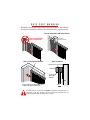
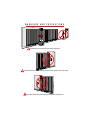
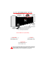
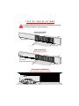
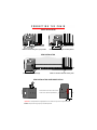
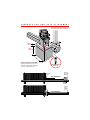
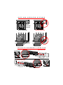
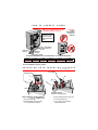
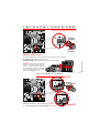
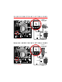
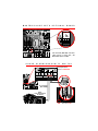
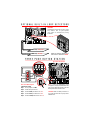
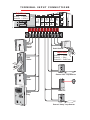
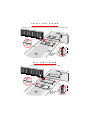
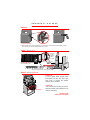
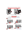
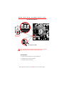
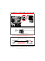
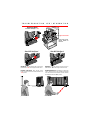
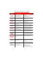
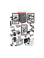
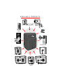
Installation Instructions Regarding the Gate Operator
A) Install the gate operator only when:
1) The operator is appropriate for the construction and the usage Class of the gate.
2) All openings of a horizontal slide gate are guarded or screened from the bottom of the gate to a minimum of 4 feet (1.2 m) above the ground to
prevent a 2 1/4inch (57.15 mm) diameter sphere from passing through the openings anywhere in the gate, and in that portion of the adjacent
fence that the gate covers in the open position.
3) All exposed pinch points are eliminated or guarded, and
4) Guarding is supplied for exposed rollers.
B) The operator is intended for installation only on gates used for vehicles. Pedestrians must be supplied with a separate access opening.
C) The gate must be installed in a location so that enough clearance is supplied between the gate and adjacent structures when opening and closing to
reduce the risk of entrapment. Swinging gates shall not open into public access areas.
D) The gate must be properly installed and work freely in both directions prior to the installation of the gate operator.
E) F) Controls must be far enough from the gate so that the user is prevented from coming in contact with the gate while operating the controls. Controls
intended to be used to reset an operator after 2 sequential activations of the entrapment protection device or devices must be located in the line of sight
of the gate outdoor or easily accessible controls shall have a security feature to prevent unauthorized use.
G) All warning signs and placards must be installed where visible in the area of the gate.
H) For a gate operator utilizing a non-contact sensor such as a photo beam:
1) See instructions on the placement of non-contact sensor for each Type of application,
2) Care shall be exercised to reduce the risk of nuisance tripping, such as when a vehicle trips the sensor while the gate still moving, and
3) One or more non-contact sensors shall be located where the risk of entrapment or obstruction exists, such as the perimeter reachable by a
moving gate or barrier.
I) For a gate operator utilizing a contact sensor such as an edge sensor:
1) One or more contact sensors shall be located at the leading edge, trailing edge and postmounted both inside and outside of a vehicular
horizontal slide gate.
2) One or more contact sensors shall be located at the bottom edge of a vehicular vertical lift gate.
3) One or more contact sensors shall be located at the pinch point of a vehicular vertical pivot gate.
4) A hardwired contact sensor shall be located and its wiring arranged so that the communication between the sensor and the gate operator is
not subjected to mechanical damage.
5) A wireless contact sensor such as the one that transmits radio frequency (RF) signals to the gate operator for entrapment protection functions
shall be located where the transmission of the signals are not obstructed or impeded by building structures, natural landscaping or similar
obstruction. A wireless contact sensor shall function under the intended end-use conditions.
Important Safety Instructions
WARNING - To Reduce the Risk of Injury or Death:
1. READ AND FOLLOW ALL INSTRUCTIONS!
2. Never let children operate or play with gate controls. Keep the remote control away from children.
3. Always keep people and objects away from the gate while the gate is in operation. NO ONE SHOULD CROSS THE PATH OF A MOVING GATE.
4. Test the gate operator monthly. The gate MUST reverse on contact with a rigid object or stop when an object activates the non-contact sensors. After
adjusting the force or the limit of travel, retest the gate operator, Failure to adjust and retest the gate operator properly can increase the risk of injury or
death.
5. Use the emergency release only when the gate is not moving. Make sure the power for the gate operator is off.
6. KEEP GATES PROPERLY MAINTAINED. Read the manual. Have a qualified service person make repairs to the gate or gate hardware.
7. The entrance is for vehicles only. Pedestrians must use separate entrance.
8. SAVE THESE INSTRUCTIONS.
Gate – A moving barrier such as a swinging, sliding, raising lowering, rolling, or like, barrier, that is a
stand-alone passage barrier or is that portion of a wall or fence system that controls entrance and/or
egress by persons or vehicles and completes the perimeter of a defined area.
Vehicular horizontal slide-gate operator (or system) – A vehicular gate operator (or system) that
controls a gate which slides in a horizontal direction that is intended for use for vehicular entrance or
exit to a drive, parking lot, or the like.
Residential vehicular gate operator – Class I – A vehicular gate
operator (or system) intended for use in a home of one-to four single
family dwelling, or a garage or parking area associated therewith.
Class I
Commercial/General access vehicular gate operator – Class II
– A vehicular gate operator (or system) intended for use in a
commercial location or building such as a multi-family housing
unit (five or more single family units) hotel, garages, retail store
or other building servicing the general public.
Class II
Commercial/General access vehicular gate operator – Class III –
A vehicular gate operator (or system) intended for use in a
industrial location or building such as a factory or loading dock
area or other locations not intended to service the general public.
Class III
Restricted access vehicular gate operator – Class IV – A
vehicular gate operator (or system) intended for use in a
guarded industrial location or building such as an airport
security area or other restricted access locations not servicing
the general public, in which unauthorized access is prevented
via supervision by security personnel.
Class IV
IMPORTANT! Because gate coasting distance varies with temperature, Elite DOES NOT
recommend the installation of a catch post. This could cause the gate to collide with the post.
Correct Installation with Catch Rollers
Incorrect Installation
using a Catch Post!
Gate in Fully Opened Position
Guide Rollers
(Elite Part # A UHM)
Gate Clearances
1/4" Clearance from Top of Gate
Catch Rollers
1/2" Clearance
Between Gate
and Rollers
Wall
Minimum Clearance of 5" Between Back of Gate
and Wall or Other Objects in Gate's Path
Gate
For safety reasons, a physical stop MUST be installed on the gate prior to
installation of the gate operator. This will assure that the gate does not
exceed movement limits and derail while in motion.
CAUTION
IMPORTANT NOTICE!
Installers are required to adhere to this
procedure: The UL required Warning
Signs must be installed in plain view
and on both sides of each gate
installed. Each sign is made with
fastening holes in each corner and
should be permanently secured in a
suitable manner. Also the warning
sticker should be placed on the
operator so it is clearly visible.
Warning Signs on Both Sides of Gate
Warning Sign Clearly Visible on Gate Operator
Owners Must Never Let Pedestrians Cross the Path of a Moving Gate!
CAUTION
Owners Must Never Mount Any Gate Operating Devices Accessible In Between the Gate and the Wall!
CAUTION
Owners Must Never Mount Any Gate Operating Devices Accessible Through the Gate!
CAUTION
Warning Signs on Both Sides of Gate
3" Maximum Picket Width
2"x 2" Mesh Wire
Across Entire Gate
Guide Rollers
Guide Rollers
Over-Travel Stops
on Both Ends of
Gate Rail
Steel V-Groove, High Speed Ball Bearing Wheels
Warning Sign Clearly Visible on Gate Operator
115 VAC for Each
Gate Operator
Reinforced Concrete to Bolt Operator on
U.L. Listed Underground Conduit for Wires
Pedestrians MUST have a Separate Walkway!
SL-3000-UL-DM
SL-3000-UL
Two-1/2 hp Motors, 120 VAC, 4.7 amp.
Maximum Gate Length – 37 feet
Maximum Gate Weight – 800 lbs.
1/2 hp Motor, 120 VAC, 4 amp.
Maximum Gate Length – 37 feet
Maximum Gate Weight – 1000 lbs.
SL-3000-UL-1HP
Two-1/2 hp Motors, 120 VAC, 8.4 amps.
Maximum Gate Length – 37 feet
Maximum Gate Weight – 2000 lbs.
Be sure to read and follow all Elite and UL instructions before installing and
operating any Elite products. Elite Access Systems, Inc. is not responsible for
improper installations or failure to comply with local building codes.
It is highly recommended installing over-travel stops at both ends of the gate
rail in any type of installation, to prevent derailing.
FRONT INSTALLATION
Reason: Cost effecient
Over-Travel Stop
Over-Travel Stop
REAR INSTALLATION
Reason: Chain is not visible
Over-Travel Stop
Idler Wheel must have Safety Cover
Over-Travel Stop
CEILING MOUNT UNDERGROUND
Reason: Space effecient/chain is not visible
FRONT INSTALLATION
Weld front bracket with gate in open position.
Weld rear bracket with gate in closed position.
REAR INSTALLATION
Cut the cover 17 1/2 inches high.
Make sure the idler wheel has a safety cover.
REAR INSTALLATION COVER MODIFICATION
Cut the chain access slot on the one side
of the cover to the exact specifications.
17.5"
2"
Important: For safe operation of the gate opener do not cut the slots any wider or longer than shown.
DO NOT modify the housing in any way other than specified.
C O N C R E T E
P A D
A N D
G A T E
A T T A C H M E N T
Follow gate manufacturers specifications
and local building codes for setting post.
12"
12"
Above
Ground 6"
10"
Below 24"
Ground
8"
24"
24"
Concrete (Reinforced Recommended)
Suggested installation for dirt ground.
The measurements depend on the type of
ground (ie., asphalt, cement, dirt)
Red Head Fastener
1/2" x 3 1/2"
Over-Travel
Stops on Both
Ends of Rail
Cover over
Wheel
Rear Installation
Over-Travel
Stops on
Both Ends
of Rail
Front Installation
G A T E
A N D
O P E R A T O R
D I S T A N C E
4"
Minimum
Distance
Between Gate
and Sprocket
Correct Installation
C H O O S I N G
Omni Control Board
CENTER
SAFETY
Incorrect Installation
M O V E M E N T
D I R E C T I O N
Open to the Left
MER
60
EXIT
1
OFF
3
ON
DC-BACKUP
W4
GB A
MS LINK
SYSTEM ON
SENSORS
TIMER
13 13
OFF
60
ON
3
13
POWER
OVERLOAD
OPEN LEFT
OPEN RIGHT
OPEN LEFT OPEN RIGHT
FIRE
DEPT.
STRIKE RADIO
GATE
OPEN RECEIVERLOCKED
EXIT
LOOP
SAFETY CENTER RESET
MOTOR
LOOP LOOP
RADIO
Open to the Right
Omni Control Board
MER
60
CENTER
1
OFF
SAFETY
EXIT
3
ON
DC-BACKUP
W4
GB A
MS LINK
OPEN LEFT
RADIO
OPEN RIGHT
SYSTEM ON
SENSORS
TIMER
60
13 13
OFF
ON
3
13
OPEN LEFT OPEN RIGHT
FIRE
DEPT.
STRIKE RADIO
GATE
OPEN RECEIVER LOCKED
EXIT
LOOP
SAFETY CENTER RESET
MOTOR
LOOP LOOP
POWER
OVERLOAD
H O W
T O
C O N N E C T
P O W E R
Do Not Use This Outlet Unless You Are
An Authorized Service Technician
Minimum:
15-Amp
Breaker Switch
Per Operator
Required
Suggestion:
Seal all open holes of
electronic box with
sealant when finished
wiring.
White Wires
(Neutral)
Use U.L. Listed Conduit
for Supplying Power to
the Unit
Black Wires
(120 VAC)
Green Wires (Ground)
WIRE GUAGE REQUIREMENT FOR 120 VAC POWER SUPPLY: 1/2 HP AND DUAL MOTOR ONLY
16 Gauge
150 Feet
14 Gauge
250 Feet
12 Gauge
400 Feet
10 Gauge
650 Feet
8 Gauge
1000 Feet
4 Gauge
2200 Feet
Caution: ELITE ACCESS SYSTEMS, INC. is not responsible for conflicts between the information listed in the above chart and the requirements
of your local building codes. The information is for suggested use only. Check your local codes before installation.
Gate Operator MUST be properly grounded.
A D J U S T I N G
G A T E
T R A V E L I N G
D I S T A N C E
Nut
Push Plate
Plate
Each notch indicates an
estimated 1 inch of gate travel
Before Adjusting, Do the Following:
1.Turn the Power OFF!
2. Push the plate inward. Roll the
nut to the direction desired.
3. Place the plate back in the notch.
4. Turn the machine off.
5. If you need more adjusting,
repeat the process.
Adjusted by Qualified Service Personnel
CENTER
SAFETY
EXIT
Maximum
Sensitivity
1
3
DC-BACKUP
W4
G B
A
SYSTEM ON
MS LINK
TIMER
SENSORS
60
3
1
POWER
3
1
OFF
1
OVERLOAD
3
ON
3
OPEN LEFT
OPEN RIGHT
STRIKE
OPEN
RADIO
RECEIVER
EXIT
SAFETY
CENTER
RESET
LOOP
MOTOR
LOOP
LOOP
Minimum
Sensitivity
GATE
LOCKED
FIRE
DEPT.
DO NOT Touch Alarm Sensor
The level of sensitivity has to do with the weight of the gate and the condition of installation.
Too sensitive = if the gate stops or reverses by itself.
Not sensitive enough = if the gate hits an object and does not stop or reverse.
CAUTION: If the power supply to the gate
operator is less than 99 volts, adjust the
alarm by turning the alarm adjustment
counter-clockwise enough to actuate the
alarm when obstructed but not sensitive
enough for false triggering to occur.
A D J U S T A B L E
T I M E R
Timer ON
TIMER
CENTER
SAFETY
60
EXIT
OFF
ON
OPEN LEFT
3
1
Set Timer
1 to 60 seconds
3
OPEN RIGHT
DC-BACKUP
W4
GB
MS LINK
A
SYSTEM ON
TIMER
SENSORS
60
3
1
OFF
1
3
1
ON
3
POWER
OVERLOAD
TIMER
3
OPEN LEFT
60
3
OPEN RIGHT
FIRE
DEPT.
STRIKE
OPEN
RADIO
RECEIVER
GATE
LOCKED
EXIT
LOOP
SAFETY
LOOP
CENTER
LOOP
RESET
MOTOR
OFF
OPEN LEFT
Timer can be set from 1 to 60 seconds (Timer ON ),
or for push open/push close type operation (Timer OFF ).
1
3
ON
OPEN RIGHT
Timer OFF
M A S T E R
A N D
S L A V E
W I T H
T I M E R
O N
Master Omni Board Primary Control for System
Master and Slave Boards are Interchangeable
Use Low Voltage Wires to Connect Gate Operators Together
Caution: 115 volts per operator required
Master Omni Board
TIMER
CENTER
SAFETY
OFF
EXIT
OPEN LEFT
60
ON
3
1
3
Adjust Time Desired
0 to 60 seconds
Slave Omni Board
OPEN RIGHT
CENTER
DC-BACKUP
GB
A
SYSTEM ON
MS LINK
TIMER
SENSORS
60
3
1
OFF
1
3
1
SAFETY
EXIT
Master Timer “ON”
W4
POWER
OVERLOAD
3
ON
3
OPEN LEFT
OPEN RIGHT
DC-BACKUP
FIRE
STRIKE
RADIO
GATE
DEPT.
OPEN
RECEIVER
LOCKED
EXIT
LOOP
SAFETY
LOOP
CENTER
LOOP
RESET
MOTOR
W4
G B
A
SYSTEM ON
SENSORS
MS LINK
TIMER
POWER
60
3
OVERLOAD
13
13
OFF
13
ON
OPEN LEFT
W4
G B A
Use Shielded
Twisted Wires
to Connect Gate
Operators Together
MS LINK
OPEN RIGHT
FIRE
DEPT.
STRIKE
OPEN
RADIO
RECEIVER
GATE
LOCKED
EXIT
LOOP
SAFETY
LOOP
CENTER
LOOP
RESET
MOTOR
W4
MAXIMUM
Counterclockwise
Setting
G B A
MS LINK
TIMER
1. Connect G from master to G of slave.
(G is the shield or a ground wire)
OFF
2. Connect B from master to B of slave.
OPEN LEFT
3
60
ON
1
3
OPEN RIGHT
3. Connect A from master to A of slave.
4. Turn timers on BOTH Omni boards to the “ON” position
5. Turn the SLAVE Timer adjustment all the way Counterclockwise
6. Use MASTER timer ONLY to select the desired time
Slave Timer “ON”
M A S T E R
A N D
S L A V E
W I T H
T I M E R
O F F
Use Low Voltage Wires to Connect Gate Operators Together
Master Omni Board
CENTER
SAFETY
Caution: 115 volts per operator required
TIMER
EXIT
60
3
Slave Omni Board
OFF
DC-BACKUP
ON
OPEN LEFT
1
3
OPEN RIGHT
W4
CENTER
GB
SAFETY
EXIT
A
SYSTEM ON
MS LINK
TIMER
SENSORS
60
3
1
OFF
1
3
1
POWER
OVERLOAD
3
ON
3
OPEN LEFT
OPEN RIGHT
FIRE
DEPT.
STRIKE
OPEN
RADIO
RECEIVER
GATE
LOCKED
EXIT
LOOP
SAFETY
LOOP
CENTER
LOOP
RESET
MOTOR
DC-BACKUP
W4
G B
A
MS LINK
SYSTEM ON
SENSORS
TIMER
POWER
60
3
OVERLOAD
13
13
W4
G B A
Use Shielded
Twisted Wires
W4
to Connect Gate
Operators Together
MS LINK
ON
OPEN LEFT
OPEN RIGHT
STRIKE
OPEN
RADIO
RECEIVER
GATE
LOCKED
EXIT
LOOP
SAFETY
LOOP
CENTER
LOOP
RESET
MOTOR
G B A
MS LINK
1. Connect G from master to G of slave.
(G is the shield or a ground wire)
2. Connect B from master to B of slave.
3. Connect A from master to A of slave.
4. Turn timers onBOTH Omni boards to the “OFF” position
P A R T I A L
OFF
13
FIRE
DEPT.
TIMER
OFF
OPEN LEFT
M A S T E R / I N D I V I D U A L
60
ON
3
1
3
OPEN RIGHT
C O N T R O L
IN ORDER FOR THE FOLLOWING OPERATION TO OCCUR, FOLLOW THE INSTRUCTIONS.
EXAMPLE: There is a double gate, the entry gate is to be opened with a radio transmitter and the
exit gate with a free exit loop. Only one safety loop system is to open both gates, and a fire
department switch should open both gates at the same time.
1. Connect the radio receiver to entry gate only.
2. Connect the exit loop to exit gate only.
3. Connect the safety loop to both entry and exit gates.
4. Connect the fire department switch to both entry and exit gates.
S O L E N O I D / M A G L O C K
J 3
C O N N E C T I O N
Wire Harness
J3
2
CENTER
SAFETY
1
3
Normally Closed
8
7
Common
10
9
EXIT
Normally Open
DC-BACKUP
W4
G B
A
MS LINK
SYSTEM ON
SENSORS
TIMER
60
POWER
3
OVERLOAD
1
OFF
1
3
1
3
ON
Connection of a Solenoid or Magnetic Lock can be made
using the J3 plug and three wires supplied with the unit.
3
OPEN LEFT
OPEN RIGHT
FIRE
DEPT.
STRIKE
OPEN
RADIO
RECEIVER
GATE
LOCKED
EXIT
LOOP
SAFETY
LOOP
CENTER
LOOP
RESET
MOTOR
Solenoid Lock
Solenoid Lock
J3
2
1
3
8
7
10
9
#3 Normally Closed
Ground
Plug-In
Transformer
#7 Common
Wire Nut
Insert 2 supplied wires
into J3 plug (#3 and #7)
(Motor Harness)
Power
Ground
Magnetic Lock
Magnetic
Lock
J3
2
1
3
8
7
10
9
Insert 2 supplied wires
into J3 plug (#7 and #8)
(Motor Harness)
Plug-In
Transformer
Ground
#7 Common
Wire Nut
#8 Normally Open
Power
Ground
QCC socket with QCC access ID inserted
QCC “Mode of Operation” switch
QCC
A B
DC-BACKUP
OPEN
STOP
CLOSE
MAGLOCK
ALARM
ARMED
M/S LINK
QCC
W4
G B A
OPEN
A
MS LINKCLOSE
STOP
B
MAGLOCKALARMARMED
SYSTEM ON
M/S LINK
TIMER
SENSORS
60
1
3
1
POWER
3
1
OFF
OVERLOAD
3
ON
3
OPEN LEFT
OPEN RIGHT
FIRE
DEPT.
STRIKE
OPEN
RADIO
RECEIVER
GATE
LOCKED
EXIT
LOOP
SAFETY
LOOP
CENTER
LOOP
RESET
MOTOR
1
2
3
4
5
6
7
8
9 10 11 12 13 14 15 16
Omni Option Board
Elite Part # O-OMNI EXB
QCC is designed for slide gate operators only!
1 & 2 – Open Command
10 & 11 – Burglar Alarm Output
3 & 4 – Stop Command
12 & 13 – Burglar Alarm Input
14 – Ground
5 & 6 – Close Command
Master/Slave
RS485
15 – B
7 – Common
8 – Normally Closed
Maglock or
Solenoid
16 – A
9 – Normally Open
Q C C
( Q U I C K
QCC Access ID (Top Positive)
C L O S E
C U R C U I T )
QCC Access Socket
Mode of Operation Switch
QCC Access ID
Elite Part #
O-QCC OMNI
Omni Option Board
Elite Part # O-OMNI EXB
the QCC can operate in two different modes. The mode of operation will depend on the switch on the Omni option
board.
Mode A (switch off) If the gate is closing while a car is driving over the safety loop detector, the QCC will stop the
gate for a second then open the gate while the car is over the safety loop detector. As soon as the car leaves the
safety loop, the QCC will resume closing the gate.
Mode B (switch on) If the gate is closing, and a vehicle drives over the safety loop, the QCC will stop the gate. It
will not open the gate. After the vehicle leaves the safety loop, the QCC will close the gate.
SE
MAGLOCK
7 – Common
8 – Normally Closed
AL 9 – Normally Open
Solenoid Lock
CENTER
SAFETY
EXIT
7
8
9
Ground
DC-BACKUP
Plug-In
Transformer
QCC
W4
GB A
A
B
MS
LINK
OPENST
OP
CLOSE
MAGLOCKALARMARMED M/S LINK
SYSTEM ON
TIMER
SENSORS
60
3
1
OFF
1
3
1
POWER
OVERLOAD
3
ON
3
OPEN LEFT
OPEN RIGHT
FIRE
DEPT.
STRIKE
OPEN
RADIO
RECEIVER
GATE
LOCKED
EXIT
LOOP
SAFETY
LOOP
CENTER
LOOP
RESET
MOTOR
Wire Nut
Power
Omni Option Board
Elite Part # O-OMNI EXB
Ground
SE
CENTER
SAFETY
MAGLOCK
7 – Common
8 – Normally Closed
AL 9 – Normally Open
EXIT
7
8
Magnetic
Lock
9
Ground
DC-BACKUP
QCC
W4
GB A
A
MS
LINK
OPENST
OP
CLOSE
B
MAGLOCKALARMARMED M/S LINK
SYSTEM ON
TIMER
SENSORS
60
3
1
OFF
1
3
1
3
ON
3
OPEN LEFT
Omni Option Board
Elite Part # O-OMNI EXB
POWER
OVERLOAD
OPEN RIGHT
FIRE
DEPT.
STRIKE
OPEN
RADIO
RECEIVER
GATE
LOCKED
EXIT
LOOP
SAFETY
LOOP
CENTER
LOOP
RESET
MOTOR
Wire Nut
Power
Ground
Plug-In
Transformer
M A S T E R / S L A V E
W I T H
O P T I O N A L
ED
CENTER
SAFETY
M/S LINK
G
EXIT
B O A R D
B
A
DC-BACKUP
QCC
W4
GB A
A
MS
LINK
OPENST
OP
CLOSE
B
SYSTEM ON
MAGLOCKALARM ARMED M/S LINK
TIMER
SENSORS
60
3
1
OFF
1
3
1
3
OPEN LEFT
H O U S E
POWER
OVERLOAD
3
ON
OPEN RIGHT
FIRE
DEPT.
STRIKE
OPEN
RADIO
RECEIVER
GATE
LOCKED
EXIT
LOOP
SAFETY
LOOP
CENTER
LOOP
RESET
MOTOR
Use this socket (M/S LINK) if the Omni
option board is being used, and
Master/Slave option is needed.
A L A R M / P R O X I M I T Y
Omni Option Board
Elite Part # O-OMNI EXB
QCC
A
OPEN
STOP
CLOSE
B
MAGLOCKALARM ARMED M/SLINK
10
CENTER
SAFETY
S W I T C H
11
12
13
EXIT
DC-BACKUP
QCC
W4
AB
A P C L O S E MAGLOCKALARMARMED
OGP EBN S T O
M/S LINK
MS LINK
SYSTEM ON
SENSORS
TIMER
60
POWER
3
OVERLOAD
13
13
OFF
13
ON
OPEN LEFT
Use Low Voltage
Wire 20 AWG
OPEN RIGHT
FIRE
DEPT.
STRIKE
OPEN
RADIO
RECEIVER
GATE
LOCKED
EXIT
LOOP
SAFETY
LOOP
CENTER
LOOP
RESET
MOTOR
OmniControl Board
12VDC
House Alarm System
Dry Contact
2"
Max.
House Alarm
Proximity Switch
Elite Part # A PRS
CENTER
SAFETY
CAUTION:
EXIT
Use different frequencies for every single
loop detector. Turn off gate operator
(from switch on electrical box) during
installation.
DC-BACKUP
W4
G B
MS LINK
A
SYSTEM ON
TIMER
SENSORS
60
1
OFF
1
3
1
POWER
3
OVERLOAD
3
ON
3
OPEN LEFT
OPEN RIGHT
FIRE
DEPT.
STRIKE
OPEN
RADIO
RECEIVER
GATE
LOCKED
EXIT
LOOP
SAFETY
LOOP
CENTER
LOOP
RESET
MOTOR
Wire-Loop “Safety Loop”
Elite Loop detectors needed to do
this function. Elite Part # A ELD
Wire-Loop “Exit Loop”
Omni Option Board Needed
OPEN
STOP CLOSE
CENTER
1
2
3
4
5
SAFETY
EXIT
6
DC-BACKUP
QCC
W4
G B
OPEN
MS LINK
STOP
A
A
CLOSE
B
MAGLOCK
ALARMARMED
M/ S
LI NK
SYSTEM ON
TIMER
SENSORS
60
3
POWER
OVERLOAD
1
OFF
1
3
1
3
ON
3
OPEN LEFT
OPEN RIGHT
FIRE
DEPT.
STRIKE
OPEN
RADIO
RECEIVER
GATE
LOCKED
EXIT
LOOP
SAFETY
LOOP
CENTER
LOOP
RESET
MOTOR
W4
Three Push Button System
(OPEN-STOP-CLOSE)
Step 1 - Cut off jumper wire #W4.
Step 2 - Install Omni option board.
Step 3 - Connect OPEN push button to # 1 & 2.
Step 4 - Connect STOP push button to # 3 & 4.
Step 5 - Connect CLOSE push button to # 5 & 6.
Note: If using the Master/Slave board
configuration, unplug the Master/Slave link
plug on main board and connect it into the
Omni option board M/S link socket.
CAUTION: Make sure each push button is
dry contact and there are no jumper wires
between them.
3
OPEN LEFT
OPEN RIGHT
FIRE
DEPT.
STRIKE
OPEN
RADIO
RECEIVER
GATE
LOCKED
EXIT
LOOP
SAFETY
LOOP
CENTER
LOOP
RESET
MOTOR
OPEN
1
3
ON
MADE IN USA
STOP
3
1
OFF
CLOSE
Terminal 8 = Ground (-)
Terminal 10 = 24 DC (+)
1
REVERSE
SENSOR
Output Power
COMMAND
PROCESSED
ALARM
SENSOR
TERMINAL INPUT CONNECTIONS
1 2 3 4 5 6 7 8 9 10
Fire or
Any Key
Switch
Radio Receiver
Output Power
Card
Reader
Terminal 8 = 24 Volt
Terminal 9 = Relay
Terminal 10 = Radio Power
External “Exit” Loop Detector
Push
Button
Photo Cell
1
4
7
HELP
2
3
5
6
8
9
Phone
Entry
0
External “Safety” Loop Detector
S A F E T Y
L O O P
S Y S T E M
The safety loop prevents the gate from closing while a car or any other object remains in the gates pathway.
4'
4'
4'
Twisted
Wires
4'
From Loop
Cut
4'
1/4"
1 1/2"
4'
Typical
Fill Loop Cuts
with Proper
Sealer
E X I T
L O O P
Three Wire Layers
in Loop Cut
S Y S T E M
The exit loop automatically allows the gate to open when a car is exiting.
4'
Twisted
Wires
4'
From Loop
Cut
4'
4'
4'
1/4"
1 1/2"
4'
Typical
Fill Loop Cuts
with Proper
Sealer
Three Wire Layers
in Loop Cut
E M E R G E N C Y
R E L E A S E
Standard
Manual
Crank
Cover
1. Turn the power OFF!
2. Make sure the crank tool fits the crank input, as shown above: Turn the crank to open the gate. To speed
up the process you may use a wireless power drill (6 ”/sec).
Option 1: Elite Part #
CP-17
Pull firmly
on the “T”
Handle to
release
the chain.
Turn the power OFF to the gate operator
and unlock the fire box.
The chain is held in place by a spring loaded pin.
Option 2: Elite Part #
DC-1000U-SL
Condition A:
In case of power failure the gate opens
automatically one time and stays open.
when power is restored the operator
returns to normal condition.
Power Back-Up
Condition B:
In case of power failure the gate will not
open automatically until activated by a key
switch or push button.
for More Details
contact your Local Dealer
R E P L A C I N G
T H E
C O N T R O L
B O A R D
Disconnect 2 wire harnesses from OmniControl board. Unscrew 3 nuts to remove board.
A U D I O
A L A R M
When one of the following events happensTwice
Consecutively,
an Alarm will Sound!
To turn alarm off, cut the power or use the optional stop button. Refer to “Stop Button Alarm”
1 The gate is too heavy.
2 Objects are on the gate's track such as
mud, rocks dirt, etc.
4 The gate has one or more broken wheels.
3 The gate is hitting a wall or any other
object.
5 A moving object has hit the gate and
the gate is off the track.
Refer to the Troubleshooting Table
S T O P
B U T T O N
A L A R M
S H U T - O F F
Omni Option Board Needed
OPEN STOP CLOSE
#3
CENTER
Stop
Button
1
2
3
4
5
SAFETY
EXIT
6
#4
DC-BACKUP
QCC
W4
A B
G B A
LINK
O P E N S MS
TOP
C L O S E MAGLOCKALARMARMED M/S LINK
Install the stop
button in a secure
accessible place.
SYSTEM ON
SENSORS
TIMER
3
60
POWER
OVERLOAD
1
OFF
1
3
1
3
ON
3
OPEN LEFT
OPEN RIGHT
FIRE
DEPT.
STRIKE
OPEN
RADIO
RECEIVER
GATE
LOCKED
EXIT
LOOP
SAFETY
LOOP
CENTER
LOOP
RESET
MOTOR
W4
Cut off jumper wire #W4.
This is an important command required to stop the audio alarm in case it has been
triggered. Otherwise the alarm will sound for 5 minutes and reset itself.
Use STOP Button:
•To stop the movement of the gate in case of potential entrapment.
•To reset the audio alarm, (check for obstructions).
•To stop the gate operator while traveling.
When using the Omni option board, use the“STOP” input to connect the stop button.
S E C O N D A R Y
E N T R A P M E N T
P R O T E C T I O N
Wiring Installation
OmniControl Board
CENTER
SAFETY
P
EXIT
DC-BACKUP
W4
G B
Edge Sensor
A
SYSTEM ON
MS LINK
TIMER
SENSORS
3
60
POWER
OVERLOAD
1
1
1
3
3
ON
OFF
3
OPEN RIGHT
OPEN LEFT
FIRE
DEPT.
STRIKE
OPEN
RADIO
RECEIVER
GATE
LOCKED
EXIT
LOOP
SAFETY
LOOP
CENTER
LOOP
RESET
MOTOR
Mounting Installation
Drill 1/2" Hole if necessary to Feed Wire Through
2 Wires to
Gate Operator
Omni Control
Board
Use #10 Screws as Necessary to Mount Edge
Black Mounting Tab
All of the installed edge sensors are connected in parallel at the sensor input
terminals on the Omni control board.
Top View of Gate Operation Recommended Installation Locations
Recommended Edge Sensor Locations
Wall
Wall
Gate
Edge Sensor
Recommended
Location
Install edge sensors appropriately at
recommended locations to insure
sufficient entrapment protection for
your installation to prevent injury.
SL
Operator
Edge Sensor
Recommended
Location
If you are going to use a contact sensor as a secondary entrapment protection you should
use a recognized component to comply with the revised UL 325 for use in class I or class II
gate operator.
Electric Sensing Edge, Miller Edge Models: MGR20 or MGS20
T R O U B L E S H O O T I N G
L E D
I N F O R M A T I O N
Resetting Motor
Reset Motor LED Light is “ON”
Motor Reset Button
Press firmly to reset
thermal breaker on
the motor.
Gate Will Not Close!
Gate Will Not Open!
Symptom: The radio receiver LED on the control
Symptom: The radio receiver LED on the control
board remains “ON” when using the remote control.
board remains “OFF” when using the remote control.
Possible Solutions: Stuck remote control
Possible Solutions: Dead battery in the remote
button. The radio receiver has malfunctioned in the
“ON” position.
control. Remote control code switches are different
from radio receiver code switches. The radio receiver
has malfunctioned in the “OFF” position.
T R O U B L E S H O O T I N G
CONDITION
POSSIBLE CAUSES
T A B L E
SOLUTIONS
OVERLOAD LED ON
And
POWER LED OFF
1.Short circuit at terminals 8 and 10
2.Short circuit at any of the loop
detectors in the board
3.Short circuit in the control board
OVERLOAD LED ON
And
POWER LED ON
1.Excessive current draw at terminal 10 1.Reduce the accessories load from
2.Over-voltage at the 120 VAC line input
terminal 10
2.Verify your electrical power
SYSTEM ON LED
FLASHING
1.One limit switch is faulty
2.Motor thermal fuse has poped-out
1.Remove the short circuit condition at
the terminals
2.Remove the defective loop detector
3.Send the board to repair
1.Test the limit switches and wire
connections, fix the fault
2.Reset the motor
REVERSE SENSOR LED 1.Gate has encountered and obstruction 1.Remove the obstruction
during traveling
2.Turn the reverse sensor switch counter
ON
2.Reverse sensor is extra sensitive
clockwise a little more and try again
ALARM SENSOR
LED ON
1.Gate encountered an obstruction
during traveling
2.Alarm sensor is extra sensitive
1.Remove the obstruction
2.Turn the alarm sensor switch counter
clockwise a little more and try again
ALARM SENSOR
LED ON
1.Gate encountered and obstruction
during traveling
2.Alarm sensor is extra sensitive
1.Remove the obstruction
2.Turn the alarm sensor switch counter
clockwise a little more and try again
COMMAND PROCESSED 1.There is a command hold active
LED ON
TIMER LED BLINKING
And COMMAND
PROCESSED
LED BLINKING
1.There is a command holding the gate
open
TIMER LED BLINKING, 1.Gate has reopened because it
COMMAND PROCESSED
encountered an obstruction while
LED BLINKING And
closing.
REVERSE SENSOR
LED ON
AUDIO ALARM ON
ANY “LOOP LED” ON
And
NO VEHICLE ON THE
SENSING AREA
1.This is a normal response of the gate
operator. It does not represent necessarily
that there is a problem.
1. This is a normal response of the gate operator.
It does not represent necessarily that there is a
problem. Check inputs for command.
1.Any re-new command will resume normal
operation. Check for obstructions.
1.Gate has encountered two
1.Any re-new command will resume normal
consecutive obstructions while trying
operation but not a radio command. Check for
to close or open
obstructions.
2.You can stop the alarm by using the stop
button.
1.The loop detector needs to be reset.
2.The wire loop has been disrupted
3.The loop detector needs to work in a
different frequency
4.The loop detector is too sensitive
1.Reset the loop detector (If you use Elite
Plug-in Loop detectors, change the setting
for sensitivity and come back to your original
setting).
2.Verify and correct connections
3.Set a different working frequency
4.Decrease the sensitivity of the loop detector
S L - 3 0 0 0
P A R T S
Limit Switch
Assembly
Power Back-Up
SL
Q010
Q164
*Q029
SL DM
*Q032
Q065
O-DC
Q031
Q123
Q051
*Q101
Q209
Q033
Q143
O-DC-SL
O-DC-SL DM
Q023
Q024
Q177
Q254
Electronic Box
Assembly
Q030
Q421
Q028
Q039
Q237
Q025
Q020
Q027
Q420
Q021
Q112
Q402 1/2 HP
Q403 1 HP
Q014
Q018
Q016
Q408
Q015
A H-110
#41
*Q013
Q404
Q401
Q400
A H-113
A H-111
#40
A ELD
A H-125
Q006
O-OMNI EXB
Q005
*Q003
*Q004
Q009
O-QCC OMNI
Note: *Sold Individually, 2 Shown.
For part names, refer to parts list
S L - 3 0 0 0
P A R T S
L I S T
AH-110 - Gate Chain No.41 (10 ft)
A H-111 - Gate Chain No.40 (10 ft)
A H-113 - Master Link, Nickel Plated
A H-125 - Master Link
Limit Switch Assembly
Q003 - Chain Bolt
Q010 - Limited Switch Box Cover
Q004 - Chain Bracket
Q023 - Limit Switch Box
Q005 - SL-3000 Chassis
Q006 - PC Board Nuts (1 Set)
Q024 Q031 - Limit Switch / Shaft
Q032 - Limit Switch Adjustment Nuts Q009 - Electronic Access Panel
Q014 - Drive Sprocket
Q051 - Limit Switch / Shaft Bearing
Q015 - Gear Reducer
Q101 - Limit Switch Bearing Holder
Q016 - Limited Switch Drive Sprocket
Q018 - 1/2 HP Electric Motor
Power Back-Up Unit
Q020 - Drive Belt
Q065 - Drive Belt (DM)
Q021 - Gear Pulley
Q123 - Back-Up Motor DC 12V Q025 - Motor Pulley
Q143 - Chassis DC Back-Up
O-DC-SL
Q027 - Motor Capacitor
O-DC-SL DM Q164 - Drive Belt
Q028 - Manual Crank
Q177 - Wire Harness DC-1000 Q029 - Limit Switch
Q209 - Pulley DC-1000 1/2 ID Q030 - Limit Switch / Chain
Q033 - Limit Switch Sprocket
Q039 - Drive Belt, DM and 1 HP
Electronic Box Assembly
Q112 - Wire Harness-B Terminal Block
Q402 1/2 HP
Q403 1 HP
Q237 - Crank Input
Q254 - Cover HD Polyethylene
Flexible Assembly for 1/2 Horse Motor
Q400 - OMNI Main PCB
Q420
Wire Harness and Conduit
Q401 - OMNI 1 Horsepower Board #
Q404 - OMNI Alarm
Flexible Assembly for Dual Motor
Q408 - Electronic Power Strip
Q421
Wire Harness and Conduit
A ELD - Loop Detector #
Muliple Parts “Q” Numbers
O-OMNI EXB - OMNI Option Board#
#OmniControl Board Accessories
O-QCC OMNI - QCC Access ID#
Idler Sprocket Assembly
Q013
M A I N T E N A N C E
1.
2.
3.
4.
5.
6.
Make sure the reversing sensor is functioning properly. Refer to “Reverse Sensor”.
Make sure the gate track is clear of dirt, rocks or other substances.
Make sure the wheels are operating smoothly on the track.
If you hear an Alarm, Refer to “Audio Alarm”.
Clean the cover on a regular basis.
For part illustrations, Refer to “SL-3000 Parts”.
If you need further assistance, please contact your local service company.
External “Safety” Loop Detectors
Remote
Control
System
Three Push
Button
Key Switch
Card Reader
Photo Electric Eye
Outdoor Digital Lock
Outdoor Digital Lock
with Intercom
Key Station
Indoor Intercom
Speaker
Outdoor Intercom
Speaker