1
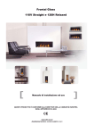
Natural Fires
BF110V / Straight and BF120H / Relaxed
40010550
0441
Installation Guide and User Manual
UK/IRL
2<<<<
UK/IRL
Content
Content ....................................................................... 1
Content ....................................................................... 3
1.
Introduction .......................................................... 5
2.
Safety instructions .................................................. 6
3.
Installation requirements.......................................... 7
3.1 Builders opening and surround .................................................. 7
3.2 Dimensions of the fire place.................................................... 10
3.3 Flue requirements................................................................ 17
4.
4.1
4.2
4.3
4.4
3.3.1
Terminal position....................................................................... 20
3.3.2
Using an existing chimney as air inlet............................................... 21
Instalation-instructions ...........................................22
Gas connection ................................................................... 22
Preparing the appliance......................................................... 22
Installing the appliance with the Faber false chimney breast ............ 23
Installing the appliance in an existing or different false chimney breast.23
4.4.1 Preparing the surround .................................................................... 23
4.4.2 Installing the appliance ................................................................... 24
4.4.3 levelling and fixating the appliance..................................................... 24
4.4.4 Building the false chimney breast ....................................................... 24
4.5. Removing/placing the glass ................................................... 25
4.5.1 Removing/placing the glass of the BF110V / Straight ................................ 25
4.5.2 removing/placing the glass of the BF120H / Relaxed ................................ 26
4.6 placing and adjusting the frame ............................................... 27
4.7 Placing the log set with the log burner ....................................... 28
4.8 Placing the pebbles with pebble burner ...................................... 28
5.
Installation of the flue ............................................29
5.1 Connections with use of concentric duct material.......................... 29
5.2 Connection onto an existing chimney ......................................... 29
5.3 Remote control ................................................................... 30
5.3.1 Installation remote control ............................................................... 31
6.
Commisioning (functional checks) ..............................33
6.1. Check pilot ignition ............................................................. 33
6.2 Functional burner check ........................................................ 33
6.3 Functional balanced flue check ................................................ 34
6.4 Check reference pressure and burner pressure ............................. 34
7.
Final check and handing over....................................36
>>>>3
UK/IRL
8.
Servicing .............................................................37
8.1 Routine servicing ................................................................. 37
8.1.1 Cleaning the glass .......................................................................... 37
8.1.2 Cleaning the combustion chamber and burner ........................................ 38
8.1.3 Burner tray (dis)assembly ................................................................. 39
8.1.4 Gas control block ........................................................................... 39
8.2 Propane conversion .............................................................. 39
8.3 Combustion test .................................................................. 39
8.4 List of spare parts ................................................................ 40
User guide...................................................................41
9.
Safety instructions for the user .................................43
9.1 General safety instructions ..................................................... 43
10.
Controlling the appliance.........................................45
10.1 General ........................................................................... 45
10.2 To light ........................................................................... 46
10.3 To extinguish .................................................................... 46
10.3.1 When the pilot extinguishes............................................................. 46
10.4 Remote control version ........................................................ 47
10.4.1 Using the remote control ................................................................ 47
10.4.2 Setting the right transmission code.................................................... 48
10.4.3 Changing the batteries................................................................... 48
11.
Cleaning and service instructions ...............................49
12.
Disposal of packaging and appliance ...........................50
Appendix: technical data.................................................51
4<<<<
UK/IRL
1. Introduction
Note: these instructions should be read carefully and retained for future reference.
Please leave these instructions with the user.
This guide is concerning the following types of appliances:
•
BF110V / Straight frameless with log burner (Faber false chimney breast optional);
•
BF110V / Straight frameless with pebble burner(Faber false chimney breast optional);
•
BF110V / Straight with frame and log burner;
•
BF110V / Straight with frame and pebble burner;
•
BF120H/Relaxed frameless with flat fibre burner and logset;
•
BF120H/Rlaxed frameless with pebble burner;
•
BF120H/Relaxed with frame and flat fibre burner and logset;
•
BF120H/Relaxed with frame and pebble brander.
Special features:
-
The frameless models of the Natural Fires feature a patented window construction;
-
A specially designed Faber prefab false chimney breast is optional (only for the
frameless versions of the Natural Fires);
-
Realistic flame and glow effect because of the "Log burner" technology;
-
Room sealed appliance, inlet and outlet are led to the outside using a natural draught
concentric pipe system (100 mm/150 mm). No additional ventilation required;
-
Air supply and flue-gases go to outside atmosphere through wall or roof. A maximum
horizontal extension of 6 meters is possible;
-
Remote Control option on all appliances;
-
Meets the essential requirements of the European Gas Appliance Directive (GAD) and
carries the CE mark according the NEN 613 standard.
>>>>5
UK/IRL
2. Safety instructions
Before installation, ensure that the local distribution conditions (identification of the type
of gas and pressure) and the adjustment of the appliance are compatible. This information
can be found on the data plate. This gas appliance is factory set and shall not be adjusted.
This appliance does not contain any component manufactured from asbestos or any asbestos
related products.
The pilot and flame sensing device fitted to this fire is also a safety device. If for any
reason any part of the pilot assembly is to be replaced, the entire assembly, including the
pilot burner, thermocouple, electrode and injector, must be exchanged complete for a pilot
assembly from the original manufacturer only.
Do not put extra (glow-)elements in the combustion chamber. This could affect the burning
process in a negative way.
This appliance is room-sealed and doesn't require purpose provided ventilation.
It is the law in the UK that all gas appliances are installed and checked by a competent
person in accordance with the Gas Safety (Installation and Use) Regulations (as amended),
the relevant British Standards for Installation work, Building Regulations, Codes of Practice,
and the manufacturer’s instructions.
The installation should also be carried out in accordance with the following where relevant:
•
British Standards: BS5871 Part1, BS5440 Parts 1 & 2 and BS1251;
•
Building Regulations Document J (as applicable);
•
Building Regulations and Standards issued as relevant by the Department of the
Environment or the Scottish Development Department.
In the Republic of Ireland installation should be carried out in accordance with IS813, ICP3,
IS327, Building Regulations, Codes of Practice, the manufacturer’s instructions and any
other rules in force.
Failure to comply with the above could leave the installer liable to prosecution and
invalidate the appliance warranty.
The construction of the fire place is not to be altered.
Safety instructions for the user can be found in chapter 9.
6<<<<
UK/IRL
3. Installation requirements
Note: Since the appliance is a source of heat, circulation of air occurs. Therefore it is of
importance that you do not use the appliance shortly after a renovation of the home. Because
of the natural circulation of air, moist and volatile components from paint, building materials,
carpet etc. will be attracted. These components can settle themselves down onto cold
surfaces in the form of soot.
As on all heat producing appliances, soft furnishings such as blown vinyl wallpaper placed too
near to the appliance may become scorched or discoloured. This should be born in mind
when installing the appliance.
3.1 Builders opening and surround
Both the BF110V/Straight frameless and the BF110V/Straight frameless can be build in an
optional Faber prefab false chimney breast made of promatec. This false chimney breast is
specially designed to accommodate this type (NOT for the models with frame) and is
applicable for ceiling heights up to 2,9m. It consists of a base part and either a top part
made of promatec or an ornamental flue pipe made of stainless steel.
The fire place can also be build in a non-combustible fire place or builders opening. This
could be either an existing builders opening or a new made prefab builders opening. For the
measurements, see paragraph 3.2.
When you apply your own false chimney breast design to all models of the BF110V/Straight
or BF120H/Relaxed, you have to meet these general requirements:
•
The false chimney breast has to be made of inflamable material;
•
The minimum inner width of the false chimney breast has to be at least 976mm (see
paragraph 3.2) and is secured by the floor plate;
•
Minimum distance from the back of the appliance to the wall has to be 10mm;
•
Always install the fire place first, before building up the false chimney breast;
•
Always ventilate the space above the appliance using vents to assure a good aircirculation;
•
If the appliance is to be fitted against a wall with combustible cladding, the cladding
must be removed from the area covered by the surround;
•
The plaster of the outside has to be resistant to a high temperature. Therefore use the
>>>>7
UK/IRL
plaster materials especially made for this, to prevent discoloring (min. 100 °C
temperature resistant);
•
Make sure the plaster dries well before using the appliance. Let the thickness in mm
be the number of days the plaster has to dry, e.g. 3 mm plaster has to dry for 3 days.
•
Although the appliance is tested for installation without a hearth, the appliance must
not stand on combustible materials or carpets. If the appliance is placed on a
combustible floor first place a fibrelux or similar heatproof board of 12 mm thickness.
Any under floor vents or openings within the builders opening should be sealed off;
•
If the floor will be adjusted (e.g. by applying carpet or parquet), the floor under the
false chimney breast has to be adjusted to match the future floor height;
•
Do not place any material directly onto the appliance. If possible, apply a lintel made
of cement or something similar;
•
Make sure that both the gas control block and the main gas valve are easy accessable
at all times and can be operated if necessary.
Specific requirements for making a false chimney breast for the BF110V / Straight
frameless:
•
The front opening of the false chimney breast has to be at least 460mm wide and
1100mm high, measured from the underside of the floor plate;
•
Minimum distance from the glass to any of the construction parts of the false chimney
breast should be at least 12 mm. This is the minimum distance with which the glass
can still be taken out;
•
When using a material thicker than 12mm, e.g. 50mm thick stony material, the floor
plate has to be adjusted according to the indicated pattern (see paragraph 3.2 for
construction details and dimensions);
Specific requirements for a false chimney breast for the BF110V / Straight with frame:
•
The wall opening has to be 620x1100 mm. This is smaller than the appliance!!!
•
The gas control block can be mounted on either the left or right side of the floor plate,
depending on which side makes it easier to acces it.
Specific requirements for a false chimney breast for the BF120H / RELAXED frameless:
•
The (wall) opening has to be 1050x425 mm. This is smaller than the appliance;
•
The (wall) opening depth is 50 mm. The distance between the opening and the glass
should be at least 12 mm. This is measured after finishing!
8<<<<
UK/IRL
•
Use 12 mm Promatec for the front of the false chimney breast. Building up the false
chimney breast with e.g. Ytong blocks is not possible;
•
The gas block is normally mounted on the right side of the appliance but can be place
elsewhere, thanks to a 1.2 m flexible gas line;
•
Make sure the that the top ridge of the (wall) opening is left out! (see drawings in
§3.2). This is necessary to be able to remove the glass and assure a good air
circulation!
>>>>9
UK/IRL
3.2 Dimensions of the fire place
Model/dimensions
BF110V /
BF110V /
Straight
Straight
frameless with frame
BF120H /
Relaxed
frameless
BF120H / Steel door
Relaxed
with frame
Frames
Max width outer frame
Max. height outer frame
Width opening inner frame
Height opening inner frame
Frame thickness
Distance bottom appliance - bottom frame
n/a
n/a
n/a
n/a
n/a
n/a
640
1125
460
945
36
62
n/a
n/a
n/a
n/a
n/a
n/a
1180
650
960
430
38*
41**
250
300
150
200
n/a
free
Installation Dimensions
Width wall opening/width dag
460
Height wall opening/height dag
1100
Max. wall thickness/depth fireplace opening 75****
Bottom applicance - bottom wall opening
n/a
Max. width applicance
976/608***
Max. height applicance
1181
Min. depth applicance (from wall)
348
616
1050
1166
224
1100
425
636
270
24
62****
24
zelf bepalen
74
159
43**
n/a
n/a
976/608*** 1600/1155*** 1600/1160***
1181
688
688
12
309
388
310
12
Flue Dimensions
Distance wall - flue pipe
Distance wall - DC-connection
*
**
***
****
159
n/a
159
n/a
135
139
135
139
frame thickness with 3mm play
distance higher than the floor plate
Width floor plate / with DC-box
Depth builders opening including distance to the glass
On the next few pages the dimensions of the BF110V / Straight and BF120H / Relaxed are
visualised in drawings.
10 < < < <
n/a
n/a
UK/IRL
[
BF110V / Straight
]
Frameless
Top view false chimney breast:
Top view of the appliance:
> > > > 11
UK/IRL
[
BF110V / Straight
Frameless
Front view false chimney breast:
12 < < < <
]
[ BF110V / Straight ]
UK/IRL
With frame
Top View:
Front View:
> > > > 13
UK/IRL
[ BF120H / Relaxed ]
Frameless
Top view:
Cross section side view detail:
Cross section side view:
Front view:
14 < < < <
[ BF120H / Relaxed ]
Top View:
Front View:
UK/IRL
With frame
Cross section side:
Front View:
> > > > 15
UK/IRL
[ Operation door ]
16 < < < <
UK/IRL
3.3 Flue requirements
The appliance is of the type C11/C31. The appliance will need to be supplied with the
approved flue pipes and terminal, it is not possible to supply your own.
The minimum effective height of the flue system must be 0.5 or 1 meter, depending on the
appliance.
Flue routing;
-
The terminal locations, through the wall as well as through the roof;
-
A horizontal extension with elbows is allowed for a maximum of 6 meters (depending
on the type and situation);
-
Vertical max. 12 meters.
Determine on the base of the table 2 and 3, depending on the type and terminal position, if
the desired situation is possible. To establish this you will need to calculate:
-
The effective height (this is the real difference in height between the upper side of
the appliance and the terminal);
-
The total horizontal extension. This is the total horizontal flue length where:
o
Each elbow, which is in the horizontal area, counts for 2 meters;
o
Each 45-degree bend, which is in the horizontal area, counts for 1 meter;
o
Elbows and bends at the transition of horizontal to vertically are not to be
counted;
o
The wall mounted terminal counts for 1 meter.
Flue restrictor
If applicable, in the table is also stated the size of a flue restrictor. This restrictor needs
to be fitted in the combustion chamber when placing the appliance (see chapter 4.2).
Normally the smallest flue restrictor is fitted.
> > > > 17
UK/IRL
Example calculation 1:
Calculating horizontal extension fig. 2a:
Flue lenght C + E = 1m + 1m 2 m
Elbows D = 2m
2m
Total horizontal extension
4m
Measure or calculate effective height (Hvert)
Flue lenght A
1m
Roof mounted terinal
1m
Total effective height
2m
When calculating on basis of the
Widescreen table nr. 2: It is allowed. Remove
the flue restrictor!
When calculating on basis of the
MV100 table nr. 3: Allowed but without flue
restrictor. Remove the flue restrictor!
When calculating on basis of theMV150 table
nr. 4: Allowed but without flue restrictor.
Remove the flue restrictor!
When calculating on basis of the Roundscreen
table nr. 5: Allowed but without flue restrictor.
Remove the flue restrictor!
Example calculation 2
Calculati0n horizontal extension fig. 2b:
Flue lenght J + L = 0,5 + 0,5
1m
Elbows K + M = 2m + 2m
4m
Terminal
1m
Total horizontal extension
6m
Vertical
Flue lenght H
1m
When calculating on basis of the
Widescreen table nr. 2: Combination not
allowed.
When calculating on basis of the MV100
table nr. 3: Allowed but without flue
restrictor. Remove the flue restrictor!
When calculating on basis of the MV150
table nr. 4: Combination not allowed.
When calculating on basis of the
Roundscreen table nr. 5: Combination not
allowed.
18 < < < <
UK/IRL
BF110V with logburner
Note: the BF110V / Straight with logburner can be lead directly to the wall, using a pipe
bend.
Determine according to the table 2 the right total horizontal and vertical length. When
meeting an x, and when the values are outside the table, the combination is not allowed.
The 30 mm flue restrictor is normally preinstalled.
Tabel 2: Possible lenth and height combinations
BF110V / Straight
0
1
2
3
4
5
6
0
1
2
3
4
5
6
x
0*
x
x
x
x
x
x
x
x
x
x
x
x
0,5 x 30 x
x
x
x
x
x
0
x
x
x
x
x
1 x 30 0
1,5 40 30 0
2 40 30 0
0
0
0
0
0
0
x
0
0
x
x
0
x 0 0
30 30 0
30 30 0
0
0
0
x
0
0
x
x
0
x
x
0
3
40 40 30 0
0
0
0
30 30 0
0
0
0
0
4
50 40 40 30 0
0
0
40 40 30 0
0
0
0
5
50 50 40 40 30 30 0
50 50 40 30 0
0
0
6
50 50 50 40 40 30 0
50 50 50 30 30 0
0
7
60 50 50 40 40 40 x
50 50 40 30 30 0
x
8
60 60 50 50 50 x
x
50 40 30 30 0
x
x
9
60 60 60 50 x
x
x
50 50 40 30 x
x
x
0
Hoogteverschil in meters
BF120H / Relaxed
10 65 60 60 x
x
x
x
55 55 50
x
x
x
x
11 65 65 x
x
x
x
x
55 55 x
x
x
x
x
12 65 x
x
x
x
x
55 x
x
x
x
x
x
x
*The BF110V / Straight with logburner can be lead directly to the wall, using a bend pipe.
> > > > 19
UK/IRL
3.3.1
Terminal position
Verify if the required terminal position meets the local installation regulations regarding
disturbance, good functioning and ventilation (Also see: safety requirements).
Note:
The terminal must be located so that the outlet is not obstructed. If the flue terminal is
located within 2 meters of a footway, path or where people could come into contact with it
then a suitable terminal guard must be fitted.
Terminals located close to shared walkways, footpaths etc. could be subject to legal
constraints and this should be pointed out to the customer before installation. If in any
doubt about flue location advice should be sought from local building control, or if
appliance-related, from the manufacturer including wherever possible a dimensioned
sketch.
Avoid locating the terminal in close proximity to plastic materials such as gutters or other
combustibles. If this is unavoidable then a suitable deflector should be made.
Some important requirements for a good functioning are:
-
The wall-mounted terminal has to be at a distance of at least 0.5 meters off:
o
Corners of the building;
o
Below eaves;
o
Balcony's etc. unless the duct is dragged to the front side of the overhanging
part.
-
The roof mounted terminal has to be at a distance of at least 0.5 meters of the sides
of the roof, excluded the ridge.
20 < < < <
UK/IRL
Site in accordance with BS 5440-1:2000 and the document J
3.3.2
Using an existing chimney as air inlet
The appliance can be connected onto an existing chimney. The existing chimney then
functions as air supply, where a flexible stainless steel liner (to BS715) of 100 mm performs
the flue function. Requirements:
-
Any existing chimney used as an air supply must only service this appliance;
-
A chimney that has previously been used for solid fuel must be swept before use;
-
The existing chimney needs to be airtight;
-
The existing chimney needs to have an opening of min. 150 x 150 mm;
-
The chimney needs to be intact and well looked after;
-
Use the adjustable roof-mounted-terminal especially made for this, and the chimney
connection set;
-
The minimum distance between two terminals should be at least 450 mm.
> > > > 21
UK/IRL
4. Instalation-instructions
4.1 Gas connection
-
Installation pipes should be in accordance with BS 6891. Pipe work from the meter to
the appliance must be of adequate size.
-
The complete installation including the meter must be tested for soundness and
purged as described in the above code.
-
A means of isolation must be provide in the supply to facilitate servicing.
-
The connection should be made in 8 mm copper or similar semi flexible tube (max 1
meter). Ensure that the gas pipe does not interfere with the removal or replacement
of the burner tray of the controls.
-
The gas connection is nut and olive suitable for 8 mm pipe.
Make sure there is a gas connection with a diameter of 8 mm goes directly from the gas
meter to the appliance, with a CE-approved sealing valve G 1/2". This valve has to be
accessable at all times. Check the connection for gas leaks.
The gas connection is positioned on the right of the appliance.
You can choose to place the sealing valve on the in- or outside the false chimney breast.
When mounted inside, a small hatch has to be installed (can be ordered separately).
If the gas connection comes out of the floor in the false chimney breast, a hole of sufficient
size has to be drilled.
Mount the supplied nut and olive of 8 mm directly on the gas unit. Then you can go on
installing a fixed or flexible connection. This has to be CE certified.
When installed as described above, the burner can always be disassembled for servicing.
4.2 Preparing the appliance
1. Remove the screws from the front legs, see figure;
2. You can now remove the appliance from the floor plate.
22 < < < <
UK/IRL
4.3 Installing the appliance with the Faber false chimney breast
When the appliance is purchased with a Faber false chimney breast, then first follow the
instructions delivered with the package of the false chimney breast.
4.4 Installing the appliance in an existing or different false chimney
breast.
Read the requirements described in paragraph 3.1 before continuing with the installation!
4.4.1 Preparing the surround
1. Check if the floor and wall are sufficiently level. If necessary, improve it;
2. If the floor will be raised higher (e.g. by installing carpet or parquet), the floor
underneath the fire place has to be equally raised;
3. Insulate the back wall with promatec of comparable inflammable material;
4. Drill holes for the flue routing. Minimum height with flue routing through the back wall
is the height of the appliance plus the pipe bend. When going through the roof, a hole
with a diameter ∅ 200mm has to be drilled in the ceiling at a distance of 170 mm from
the wall to the heart of the hole. This hole
indicates the centre of the false chimney
breast. Moving it afterwards is not possible.
5. Adjust the floor plate, if necessary:
•
Drill a hole on the floor plate where
the gas connection will come out of
the floor;
•
Cut off the knockouts (A en B, see
figure) which are meant for the Faber
false chimney breast;
6. Position the floor plate and mount it to the
floor;
7. Prepare the gas connection, see paragraph
4.1.
> > > > 23
UK/IRL
4.4.2 Installing the appliance
1. Turn the 4 legs until they are extended 20 mm
2. Install the appliance with the two front legs
positioned between the supports on the floor plate;
3. Lift the appliance gently over the supports, then put
20mm
it down;
4. Make sure that the gas connection isn’t stuck
between the receiver holder and the floor plate
4.4.3 levelling and fixating the appliance
1.
Level the appliance in all directions by
adjusting the legs underneath the
appliance;
2.
Secure the legs;
3.
Secure the appliance to the wall;
4.
Install the flue routing as describes in
chapter 5.
4.4.4 Building the false chimney breast
You are now ready to build a false chimney breast
construction. If you purchased the BF110V / Straight
Frameless, you can use the distance holders on top
of the appliance to fixate the construction and keep the builders opening
at a minimum width of 460 mm. Keep in mind that this is measured with
the finishing (e.g. plaster).
Note: The width of 460 mm of the builders opening is very critical, since
this is the minimum width with which the glass can be taken out. If the
opening is made much wider, the construction of the appliance can
become visible;
Frequently check the distance from the front of the glass to any of the
construction parts of the false chimney breast is at least 12 mm for the
24 < < < <
UK/IRL
BF110V / Straight Frameless. Again,
this is to be able to take out the glass.
4.5. Removing/placing the
glass
the BF110V / Straight as well as the
BF120V / Relaxed use the same kind of
securing system for the glass. The only
1
2
difference is in the place where the
glass is secured. This has an effect on
how the glass has to be removed:
screw
sideways for the BF110V / Straight, and
up for the BF120H / Relaxed. on the
handle
following two pages removing the glass
will be explained using pictures
4.5.1 Removing/placing the glass of
the BF110V / Straight
1.
3
4
5
6
Take away the frame or the
stainless steel door.
2.
Unscrew the two screws
underneath on either side of the
glass a few centimeters.
3.
Move both handles as far towards
you as possible. The glass is now
unsecured;
4.
Grab the glass both under above.
Move the left side of the glass
towards you, then move it to the
left and down as far as possible;
5.
Bring the right side of the glas
towards you, out of the false
chimney breast;
6.
To place the glass back on the
> > > > 25
7
8
UK/IRL
appliance, follow these steps in reverse order.
Note: make sure that both handles are moved as far towards
you as possible, otherwise securing the glass won’t be possible.
1
The glass is protected with a foil which should be removed only
after the whole installation and finishing of the appliance and
false chimney breast is completed.
Make sure that the foil is removed when the appliance is used!
4.5.2 removing/placing the glass of the BF120H / Relaxed
1.
Take away the frame of the BF120H / Relaxed (see §4.6).
2.
slide the strips on either side of the appliance to the
2
outside
3.
unscrew the screw mounted on the right side of the
appliance which secures a handle (see fig. 3 and 4).
4.
Move the handle towards you. The glass is now unsecured.
5.
gently grab the glass on either side. Tilt the glass a little
3
bit backwards. If this not possible, move the handle more
downwards.
6.
lift the glass with its top in th false chimney breast.
7.
Take the glass out of the false chimney breast.
8.
To place the glass back on the appliance, follow these
steps in reverse order.
4
Note: when placing the glass make sure that the handle is
moved backwards sufficiently. If this is not the case, securing
the glass will not be possible.
The glass is protected with a foil which should be removed only
after the whole installation and finishing of the appliance and
false chimney breast is completed.
5
Make sure that the foil is removed when the appliance is used!
26 < < < <
6
1
UK/IRL
2
4.6 placing and adjusting the frame
1)
After the appliance is properly installed,
the frame has to be placed. for this purpose
a movable lip is mounted on top of the
appliance
2)
This lip can be secured by fastening two
bolts on either side of the appliance
3)
Adjust the position of the lip so that its top
3
4
edge is positioned about 3mm from the wall
(including finishing)
4)
Place the frame over the lip. Make sure it is
positioned in the middle.
5
6
> > > > 27
Met opmaa
UK/IRL
4.7 Placing the log set with the log burner
To guarantee good combustion, the log set may only be installed in the way specified on the
picture below. Never place extra elements of any kind into the combustion chamber. This
could affect the combustion in a negative way. Any other arrangement can lead to soot on
logs or window. Do not use the fire with broken or missing logs.
When preferred, ember (immitation-ash) kan be spread around the logs. Attention! Beware
that there are no embers on the air-inlet at the back.
BF110V / Straight log burner
BF120H / Relaxed flat fibre burner
BF110V / Straight pebble burner
BF120H / Relaxed Pebble burner
4.8 Placing the pebbles with pebble burner
Spread the pebbles over the bottom plate. To ensure a good combustion, spread the
pebbles equally. Make sure that the pilot burner stays free from the pilot. The pebbles do
not need further servicing. See pictures above for more details
28 < < < <
UK/IRL
5. Installation of the flue
5.1 Connections with use of concentric duct material
1. Drill a hole of ø 153 mm for the wall or roof mounted terminal;
2. Horizontal parts of the pipe have to be installed with an angle of at least 3 degrees;
3. Build up the system from the appliance;
4. Make sure you place the pipes in the right direction, the narrow end towards the
appliance;
5. Make sure the pipes are fixed sufficiently, a wall clamp every 2 m. This way the weight
of the pipes is not resting onto the appliance.
6. The outside of the pipe can be hot (140 degrees). Stay at least 50 mm away from wall
surface or ceiling. Make sure to provide sufficient heat resistant isolation when going
through the wall or roof.
7. The concentric pipes can turn loose due to expansion or cooling down. It is
recommended to fix the spring clip with a self tapping screw at inaccessible places.
8. To get the exact measure flue length you can use cut down concentric pipe, wall
mounted terminal or roof mounted terminal. To obtain a smoke sealed connection, the
inner pipe must be 20 mm longer then the outside pipe.
5.2 Connection onto an existing chimney
You can connect the appliance onto an existing chimney. The existing chimney then
functions as an air supply channel, where a flexible stainless steel liner (to BS715) of 100
mm performs the flue function. Any existing chimney used as an air supply channel must
only service this appliance.
Requirements:
- 300 mm of free space above the appliance;
- The chimney only supply’s air to this appliance;
- The existing chimney needs to be clean and very well swept;
- The existing chimney needs to be airtight;
- The existing chimney needs to have an opening of min. 150 x 150 mm.
> > > > 29
UK/IRL
Chimney side
1. Place the aluminium closure plate (A) onto the
chimney. Permanently attach and make airtight.
Fig18
2. Pull the liner (C) through the chimney.
3. Connect the liner onto the roof terminal and fix it with
the clamp provided with the chimney connection set.
4. Place the roof terminal onto the closure plate. Fixing
the chimney sealing plate (D) and place the 150 mm
grommet into the hole of the sealing plate.
Fire place side
5.
Fixing the chimney sealing plate (D) and place the 150
mm grommet into the hole of the sealing plate.
6. if necessary, install an MV-pipe on the fire place in
such a way that the chimney connection and the MVsystem is 500 mm;
7. Fix the sealing plate air tight into the builders opening
(use the isolation rope from the chimney connection
set to make the plate air tight);
8. Slide the pipe (E) 150 mm length 500mm into the
sealing plate. Slide this pipe so far that you will have a
space of 200 mm later on for assembling the liner;
9. Install the appliance;
10. Connect the flexible stainless steel liner onto a pipe using the 200 mm long, Ø 100 mm
pipe (F) as adapter;
11.Slide the outside pipe onto the appliance or concentric extension so that you have a air
tight connection.
5.3 Remote control
The remote control is only meant to regulate the flames, it functions only when the pilot
burner is ignited. It is therefore not possible to ignited the appliance with the remote
control or to shut-off the pilotflame. The radio-frequency remote control is intended for
30 < < < <
UK/IRL
fireplaces installed in a domestic setting in all EU countries except Austria, Denmark,
Finland and Greece.
Features:
-
Manual control will always remain possible.
-
The remote control is a radio frequency type and has been approved internationally.
-
The remote control generates a unique safety code every time you activate the
transmitter, its similar to those used in a car.
-
The remote control is easy to install retrospectively.
5.3.1 Installation remote control
1. Connect the mains adapter to the receiver box. The adapter is set to the correct
voltage in the factory: 4.5 V.
2. Slide the receiver box into the holder.
3. Connect the wires to the gas valve (see fig. 22).
4. Check that there are batteries in the transmitter.
5. See "Replacing batteries", see chapter 10.4.4.
6. Set the on/off switch on the receiver to "on".
fig. 22
> > > > 31
UK/IRL
Setting the right transmission code
The receiver has to learn the code from the transmitter, which is already done at the
factory. However the code disappears if the receiver is disconnected from the mains for a
longer period.
1. Push the "mod" button on the receiver and hold it for 3 seconds.
2. The green control lamp will light up and stay on. Repeat this step if it doesn't.
3. Push a button on the remote control. The control lamp on the receiver should now go
out.
4. Again push a button on the remote control. The lamp starts flashing and will switch off
eventually.
5. The receiver now recognizes the remote control. The remote control now functions.
6.
Check if you can hear a sound and the motor runs when you push a button on the
remote control.
32 < < < <
UK/IRL
6. Commisioning (functional checks)
6.1. Check pilot ignition
1. Push in and turn the control knob A from
anticlockwise to the
(small flame)
setting. You will hear a tick meaning there is ignition. Hold the knob in and wait for a
few seconds while the air is purged.
2. Bring the knob back in the start position and turn the knob several times to the
(large flame) position. Check that the pilot has lit.
3. Continue to hold in the control knob for a further ten seconds to ensure that the pilot
flame is stable.
4.
Release the knob. The pilot should remain alight.
6.2 Functional burner check
1. Turn knob (B) to max. clockwise.
2. Turn the knob (A) more anticlockwise to the position
(large flame). Now it is
possible to light the main burner.
3. Turn knob B anticlockwise to max. The main burner should light. Check for gas
soundness at all joints with leak detection fluid!
4. Check the ignition of the main burner on low and high setting.
5.
Turn knob B clockwise till
6.
Turn the knob A to
. The main burner is off.
. The pilot should go out.
> > > > 33
UK/IRL
6.3 Functional balanced flue check
1. Set the appliance on max. input.
2. Verify the flame picture, this means no flames against the window, the flame have to
come besides the logs, if not check the log layout.
3. Check if the flames are yellow after 10 minutes of operation. If you still have a blue
flame or the appliance goes out, check:
-
If the flue pipes are fitted correctly (no leakage);
-
If the wall mounted terminal is placed with the correct side up;
-
If the maximum allowable length of the flue pipe was exeeded;
-
If the appliance has the right set up. Check the ;
-
If the correct flue restrictor is installed.
A. Governor
B. Adjusting screw pilot
flame
C. Inlet pressure test point
D. Burner pressure test
point
6.4 Check reference pressure and burner pressure
The appliance is preset to give the correct heat input. No further adjustment is necessary.
Fit a pressure gauge at the burner pressure test point D to check the burner pressure. The
pressure should be checked with the appliance alight and at max.input.The setting pressure
should be as shown at the technical data. After checking the pressure, turn off the
appliance. Remove the pressure gauge and close the sealing screw. Re-light the appliance.
Turn to max. input and test around the test point D for gas soundness using a suitable leak
detection fluid.
Measuring the pressure(voordruk):
1. Turn off the gas valve on the appliance;
2. Turn the Inlet pressure test point C (see fig. 22) some and apply the (meetslang);
34 < < < <
UK/IRL
3. Check if the measured pressure is the same as the prescribed pressure;
4. Perform this measuring when the appliance burns on full capacity and when only the
pilot ignition burns;
5. When the pressure is too low, check if the gas pipes are made of material wit the right
diameter;
6. When the pressure is too high (more than 5 mBar) you can’t install the appliance and
you should contact your gas company;
7. Always check the burner pressure when the functional pressure is right.You can measure
the burner pressure by using sensor D.The pressure should match the prescribed
pressure. If this is not the case, then contactn the supplier.
Note: After checking the burner pressure, the Inlet pressure test point has to be shut and
checked for gas-tightness.
> > > > 35
UK/IRL
7. Final check and handing over
-
Instruct the customer on the full operation of the appliance.
-
Advise the customer how to clean the appliance including the glass.
-
Instruct the customer on the operation of the remote control, including the
replacement of batteries and how to set the right transmissions code.
-
Hand over these instructions including the user guide to the consumer.
-
Recommend that the appliance should be serviced by a competent person at least once
a year.
36 < < < <
UK/IRL
8. Servicing
To ensure safe and efficient operation of the appliance, it is necessary to carry out routine
servicing at regular intervals. It is recommended, that the fire is inspected/serviced by a
competent person at least once a year.
Important: turn off the gas supply before commencing any servicing. Always test for gas
soundness after refitting the appliance.
The appliance and flue connection have to be checked for gas and smoke soundness after
installation.
8.1 Routine servicing
1.
Clean (if necessary):
-
the pilot system;
-
the burner;
-
the combustion chamber;
-
the glass.
2.
Check the log lay and replace the embers (if applicable).
3.
Do the functional test as described at page 34.
4.
Check the flue system and terminal on damage and soundness (visual inspection)
8.1.1 Cleaning the glass
Depending on the intensity of use, you can get a deposit on the glass. Normally this can
be removed with an ordinary dry towel. If necessary special ceramic glass cleaner
(ceramic cook-top cleaner) can be used. To clean the glass:
1.
Remove the glass as described in paragraph 4.5;
2.
Clean the glass. Handle the glass with clean hands, wear gloves if possible;
3.
To fit the glass, proceed in reverse order. Make sure that:
1.
the log set has been installed correctly before fixing the glass.
2.
the glass sealing rope is in good condition and makes an effective seal
3.
Important: be sure that there are no fingerprints on the glass. They are
burned in the glass when not removed.
> > > > 37
UK/IRL
8.1.2 Cleaning the combustion chamber and burner
1.
Carefully remove the logs.
2.
You can clean the combustion chamber with a vacuum cleaner.
3.
Place back the logs as described in paragraph 4.6.
If the burner is visibly damaged, this can affect the distribution of the flame. If so,
then replace the burner.
Logburner
Flat fibre burner
Pebble burner /
38 < < < <
Met opmaa
Aangepaste
(RGB(41;37
A.
B.
C.
D.
E.
F.
Pilot assembly
Burner
Fixation plate
Injector
Gas control
Receiver
Met opmaa
Tekstkleur:
(RGB(41;37
Met opmaa
Tekstkleur:
(RGB(41;37
UK/IRL
8.1.3 Burner tray (dis)assembly
1.
Break the gas supply at the control valve;
2.
Remove the glass, the log set, grid and burner tray cover;
3.
Detach the gas connection at the 8 mm nut and olive;
4.
Unscrew the burner assembly and take them out of the combustion chamber.
8.1.4 Gas control block
1. Unscrew and remove the pilot system from its support and the burner plate;
2. Disconnect the ignition/spark cabel;
3. Disconnect the thermocouple from the pilot system;
4. Disconnect the gas connection from the pilot system. Mind the injector: it’s unattached;
5. The pilot system can now be removed;
6. To assemble the pilot system again, follow the steps above in reversed order.
A.
Governor
B.
Adjusting screw pilot
flame
C.
D.
Inlet pressure test point
Burner pressure test
point
8.2 Propane conversion
For conversion from propane to natural gas, you have to order a complete new propane
burner unit. Contact your supplier and give the serial number from the data plate.
8.3 Combustion test
A BS7967 combustion analysis check should be carried out using an analyser to
BS7927 positioned in the flue outlet.
Ratio CO/CO2 should be less than 0.01 within 30 minutes (100 ppm CO per 1% CO2).
A reading of CO in the room centre should give a rise of less than 9ppm over ambient,
peak reading.
> > > > 39
UK/IRL
8.4 List of spare parts
Description
Straight
Relaxed
Number
Number
Surround antracite
20847448
20847548
Surround Stainless steel
20847803
50847903
Glass
04510300
04510500
Burner G20 FB
x
20900233
Burner G20 PB
20900231
20900232
Burner G20 LB
20900230
x
Burner LPG LB
20900224
x
Adapter
20604100
20604100
Log set
20798200
20798900
Spark wire
06022030
06022030
Receiver
20604610
20604610
Remote control
20603900
20603900
Gas Control NL NG
37003089
37003089
Motor (remote control)
37003086
37003086
Pilot burner assemb. NG
20900145
x
Pilot burner assemb. LPG
20900154
x
Thermocouple
37002046
37002046
Oxypilot L1200
20605300
20605300
Snoer oxypilot L1200
06022050
06022050
Spark electrode
06006600
06006600
Embers
20793400
20793400
spray for comb. Chamber
09000008
09000008
spray for frame
09000014
09000014
40 < < < <
UK/IRL
User guide
> > > > 41
UK/IRL
42 < < < <
UK/IRL
9. Safety instructions for the user
9.1 General safety instructions
•
These instructions should be read carefully and retained for future reference.
•
Do not place flamable materials in the combustion chamber.
•
If a gas leak is found or suspected, turn off the gas supply at the meter and contact
your installer or gas emergency service.
•
Do not use the fire with a broken or damaged glass.
•
The fire has a safety device which turns off the gas supply if there is a build up from flue
gasses in the combustion room or a temporary gas cut-off. Wait at least 5 minutes
before turning the appliance on again.
•
Contact a qualified installer when the appliance goes off regularly.
•
The appliance has been designed for heating purposes. This means that all surfaces,
including the glass, can become very warm (over 100 °C). An exception to this is the
lower side of the door and the control buttons.
•
Due to the newness of materials, they may give off a slight smell for a period after initial
lighting. This is normal, odours will disperse after a few hours use.
•
Do not place curtains, clothing, laundry, furniture or other flammable materials nearby
the appliance. The required minimum distance is 100 cm.
•
Switch off the receiver of the remote control if you don’t use the fire for a long time. Do
not let children use the remote control without supervision.
•
Children should only use the remote control under supervision.
IMPORTANT
A suitable Fireguard conforming to BS6539 and BS6778 should be used with this appliance to
protect children, the elderly or infirm. Care should also be taken with pets.
In your own interest and that of safety, all gas appliances must be installed by competent
persons. Installation must be in accordance with National Regulations. CORGI registered
> > > > 43
UK/IRL
installers are required to work to recognised standards.
Note:
Since the appliance is a source of heat, circulation of air occurs. Therefore it is of
importance that you do not use the appliance shortly after a renovation of the home.
Because of the natural circulation of air, moist and volatile components from paint,
building materials, carpet etc. will be attracted. These components can settle themselves
down onto cold surfaces in the form of soot. As on all heat producing appliances, soft
furnishings such as blown vinyl wallpaper placed too near to the appliance may become
scorched or discoloured. This should be born in mind when installing the appliance.
44 < < < <
UK/IRL
10. Controlling the appliance
10.1 General
If the main burner or pilot light is extinguished for any reason, don’t try to relight the pilot
within 5 minutes. Contact a qualified installer when the appliance goes off regularly.
Depending on the model, the gas control block is positioned:
•
BF110V /Straight Frameless: behind a stainless steel door at the underside of the
appliance, mounted in the middle of the floorplate of the appliance;
•
BF110V / Straight with frame: Within the false chimney breast or surround at either
the left or right side of the appliance, mounted on the floor plate of the appliance. An
optional hatch can be purchased with this model for easy access to the gas block.
With control button A you can light the pilot. With the control button B you can adjust the
height of the flames (see figure). All Natural Fire models feature a remote control which
controls the height of the flames.
fig. 25 Gas control box
B
A
Knob A
The
is the OFF position preventing any gas from passing through the control valve to
either the pilot burner or to the main burner. By pressing the knob in it is possible to turn it
anticlockwise. The first function is to turn on the gas to the pilot- this occurs just before
reaching the
position (if the fire has not been lit for some time it may be necessary to
hold the knob in this position for some seconds to clear the air from the pipe and allow gas
to reach the pilot burner). Once gas is available at the pilot, continued rotation anticlockwise will cause the piezo igniter to spark. This is accompanied by a click at the valve
and should result in the pilot burner igniting. Once the pilot is lit, the control knob should
be held pressed in for 10 seconds. In this time the pilot flame will have heated the flame
> > > > 45
UK/IRL
supervision thermocouple sufficiently to operate a hold-on magnet within the valve. Now
turn the control knob A to the
position. This allows gas to enter control knob B.
Knob B
The { is the OFF position preventing gas entering the main burner if the pilot is lit. The knob
should be turned slowly anticlockwise. This allows gas to enter the burner and be ignited by
the pilot flame. Once ignition has taken place, the fire may be set to any level between
min. and max. by adjusting the control knob B.
10.2 To light
1.
Push in and turn the control knob (A) from
anticlockwise to the setting (small
flame). You will hear a ignition click. Check that the pilot is lit (if not, repeat).
2.
Continue to hold in the control knob for a further ten seconds to ensure that the pilot
flame is stable.
3.
Release the knob. The pilot should remain alight.
4.
Turn the control knob A to the
5.
Turn knob B slowly anticlockwise, the fire should then ignite.
6.
Adjust flames to the required level.
position.
10.3 To extinguish
1.
For the main burner turn the control knob B clockwise to position
2.
To disable knob B turn knob A to the
3.
To extinguish the pilot turn control knob A to position
.
position.
, although it is in order lo
leave the pilot permanently lit.
10.3.1 When the pilot extinguishes
Warning! When the pilot extinguishes, for whatever reason, you should wait at least 5
minutes before trying to turn it on again. Possible causes of pilot extinguish are:
-
Operating error.
-
Interference of the safety device.
46 < < < <
UK/IRL
-
Failure in the pilot flame system.
Contact a qualified installer when the appliance goes off regularly.
10.4 Remote control version
The remote control is only meant to regulate the flames from ‘off’ till ‘max.’. It functions
only when the pilot burner is ignited and knob A is in (big flame) position. It is therefore
not possible to ignite or extinguish the pilot flame with the remote control.
Note: The radio-frequency remote control is intended for fireplaces installed in a
domestic setting in all EU countries except Austria, Denmark, Finland, and Greece.
Features:
Manual control will always remain possible;
The remote control is a radio frequency type and had been approved
internationally;
The remote control generates a unique safety code every time you activate the
transmitter, its similar to those used in a car;
The remote control is easy to install retrospectively.
10.4.1 Using the remote control
1.
Light the appliance as described in 10.2;
2.
Set the on/off switch on the receiver to "on” and control the flames:
Low flame
High flame
3.
Use (high) and (low) to achieve the desired heating and flame effect;
4.
You will hear a beep every time the receiver recognises a signal. (If not, see 10.4.3,
setting the right transmission code);
5.
When the fire is not be used for a prolonged period, turn off the pilot (see 10.4.2). If
the appliance is not used for an extensive period of time, it can be necessary to set
the right transmission code again.
> > > > 47
UK/IRL
10.4.2 Setting the right transmission code
The receiver has to learn the code from the transmitter. This is already done at the factory.
However the code disappears if the receiver is disconnected from the mains too long.
1.
Set the on/off switch on the receiver to "on";
2.
Push the "mod" button on the receiver and hold it for 3 seconds;
3.
The green control lamp will light up and stay on. Repeat this step if it
fig. 27 Rear of
remote control
doesn't;
4.
Push a button on the remote control. The control lamp on the receiver
should now go out;
5.
Again push a button on the remote control. The lamp starts flashing
and will switch off eventually;
6.
The receiver now recognizes the remote control. The remote control
now functions;
7.
Check if you can hear a sound and the motor runs when you push a
button on the remote control.
10.4.3 Changing the batteries
The batteries in the remote control should have a life span of about one
year, depending on the frequency of use.There is no risk of electric shock
as the low voltage supply is similar to that used in torches. Always turn off
the appliance before changing batteries.
Remote control
1.
Remove the cover on the back of the remote control;
2.
Carefully remove the battery clip along the side. Pay attention not to
pull the wires;
3.
If necessary, remove the old batteries and place the new ones:
2x LR03 /AAA Alkaline long life 1.5 V.
4.
Click the battery clip into the remote control and close the cover;
5.
It might be possible that you have to set the transmission code after changing the
batteries (see 10.4.3).
Note: Batteries are chemical waste and should be disposed in accordance with local
regulations.
48 < < < <
UK/IRL
11. Cleaning and service instructions
Important:
Turn off the fire and allow it to cool down before commencing cleaning.
It is recommended that the fire is inspected/serviced, by a competent person at least once a
year. To maintain the finish on the trim wipe with soft damp cloth only. Do not use abrasive
cleaners, polish or solvents as these can damage the surface finish.
Cleaning the glass:
To remove the glass to clean it, follow the steps described in paragraph 4.5;
To clean the glass, follow the steps and suggestions described in paragrapg 8.1.1;
Be sure that there are no fingerprints on the glass. It is not possible to remove those
prints after you burn the appliance for a while (they are burnt in).
> > > > 49
UK/IRL
12. Disposal of packaging and appliance
The appliance packaging is recyclable. The packaging could include the following materials:
•
Cardboard;
•
CFC-free foam (soft);
•
Wood;
•
Plastic;
•
Paper;
•
Batteries.
These materials should be disposed responsibly and in conformity with government
regulations.
Batteries are considered chemical waste. The batteries should be disposed of responsibly
and in conformity with government regulations. Remove the batteries before disposing of
the remote control.
Information on how to responsibly dispose of discarded appliances can be obtained from the
local authorities.
50 < < < <
UK/IRL
Appendix: technical data
BF110V /Straight
Type of burner
Country
Category
Type
BF120H / Relaxed
log burner
UK/IRL
Pebble burner
UK/IRL
flatfiber/log
UK/IRL
Pebble burner
UK/IRL
I2H
I2H
I2H
I2H
C11 of C31
C11 of C31
C11 of C31
C11 of C31
Gas unit specifications
Type of gas
Heat input Hi (net)
[kW]
Efficiency class
NOX class
Working pressure
gas rate ( 15º C en 1013 mbar)
Setting pressure
G20
G20
G20
G20
7,2
7,3
8,2
8,2
2
2
2
2
4
4
4
4
[mbar]
20
20
20
20
[l/h]
761
780
870
870
[mbar]
9,5
10
13
13
Injector size
[mm] 2 x 1,60 + 1,50
2,55
2,55
2,55
Reduced input restrictor
[mm]
1,8
1,8
1,8
SIT 160
SIT 160
SIT 160
OP9709
Nr 51
Nr 51
1,8
Pilot assembly
Type
code injector
Flue system
MV size
[mm]
100-150
100-150
100-150
100-150
Preinstalled flue restrictor
[mm]
30
30
30
30
Gas control
GV36-
GV36-
GV36-
GV36-
C5AOEHC68M
C5AOEHC68M
C5AOEHC68M
C5AOEHC68M
Remote control
Voltage adaptor
[V]
Batteries
[V]
Gas connection
4,5
4,5
4,5
4,5
2x LR03 1.5V
2x LR03 1.5V
2x LR03 1.5V
2x LR03 1.5V
Alkaline
Alkaline
Alkaline
Alkaline
8 mm nut &
8 mm nut &
8 mm nut &
8 mm nut &
> > > > 51
UK/IRL
Saturnus 8 NL - 8448 CC Heerenveen
Postbus 219 NL - 8440 AE Heerenveen
T. +31(0)513 656500
F. +31(0)513 656501
52 < < < <