Download Learning to Use the Kvick Lab™ Cassette Holder
Transcript
18117269.book Page 1 Wednesday, February 24, 2010 2:04 PM
GE Healthcare
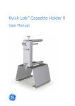
Learning to Use the Kvick Lab™
Cassette Holder
User Manual
18117269.book Page 2 Wednesday, February 24, 2010 2:04 PM
18117269.book Page 3 Wednesday, February 24, 2010 2:04 PM
Important user information
All users must read this entire manual to fully understand the safe use of
Kvick Lab Cassette Holder.
WARNING!
The WARNING! sign highlights instructions that must be followed to avoid personal injury. Do not proceed until all stated
conditions are clearly understood and met.
CAUTION!
The CAUTION! sign highlights instructions that must be followed to avoid
damage to the product or other equipment. Do not proceed until all stated
conditions are met and clearly understood.
Note
The Note sign is used to indicate information important for trouble-free
and optimal use of the product.
CE Certifying
This product meets the requirements of applicable CE-directives. A copy of
the corresponding Declaration of Conformity is available on request.
The CE symbol and corresponding declaration of conformity, is valid for
the instrument when it is:
– used as a stand-alone unit, or
– connected to other CE-marked GE Healthcare instruments, or
– connected to other products recommended or described in this manual,
and
– used in the same state as it was delivered from GE Healthcare except for
alterations described in this manual.
Recycling
This symbol indicates that the waste of electrical and
electronic equipment must not be disposed as unsorted municipal waste and must be collected separately. Please contact an
authorized representative of the manufacturer for information
concerning the decommissioning of your equipment.
18117269.book Page 4 Wednesday, February 24, 2010 2:04 PM
4
Learning to Use the Kvick Lab Cassette Holder User Manual 18-1172-69 Edition AH
18117269.book Page 5 Wednesday, February 24, 2010 2:04 PM
Contents
Contents
1
About this user guide
1.1
1.2
1.3
1.4
2
Kvick Lab Cassette Holder
2.1
2.2
2.3
2.4
2.5
3
Audience .............................................................................................................................................................................................7
Where to find more information ..............................................................................................................................................7
Safety ...................................................................................................................................................................................................9
Warnings, cautions, and expert advice ............................................................................................................................. 10
Unpacking and lifting the cassette holder ....................................................................................................................... 13
Package contents ........................................................................................................................................................................ 13
Learning about the holder ...................................................................................................................................................... 13
Features ........................................................................................................................................................................................... 14
Learning about cassettes ........................................................................................................................................................ 15
Connecting the Holder to Your System
3.1 Where to install the holder ...................................................................................................................................................... 17
3.2 How to install the holder .......................................................................................................................................................... 18
4
Installing Cassettes in the Holder
4.1 Introduction .................................................................................................................................................................................... 19
4.2 Determining how many cassettes you can install ....................................................................................................... 19
4.3 Installing the cassettes ............................................................................................................................................................. 19
5
Preparing a Cassette for Use
5.1
5.2
5.3
5.4
5.5
5.6
6
Using the Holder
6.1
6.2
6.3
6.4
7
Introduction .................................................................................................................................................................................... 33
Stage 1– Starting the cross-flow process ........................................................................................................................ 35
Stage 2 – Operating the system in a steady state ....................................................................................................... 36
Stage 3 – Shutting the system down and recovering product .............................................................................. 37
Cleaning and Storing
7.1
7.2
7.3
7.4
8
Introduction .................................................................................................................................................................................... 21
Stage 1 – Rinse storage solution from the cassette ................................................................................................... 22
Stage 2 – Measuring water flux ............................................................................................................................................ 24
Stage 3 – Test the integrity of the cassette ..................................................................................................................... 28
Stage 4 – Sanitizing the Kvick Lab cassette .................................................................................................................... 31
Stage 5 – Conditioning the system with buffer ............................................................................................................. 32
Introduction .................................................................................................................................................................................... 39
Stage 1 – Cleaning a cassette after use ........................................................................................................................... 39
Stage 2 – Measuring water flux ............................................................................................................................................ 40
Stage 3 – Storing the cassette and holder ...................................................................................................................... 40
Troubleshooting
8.1 Troubleshooting guide .............................................................................................................................................................. 41
9
Maintenance
9.1 Inspection ........................................................................................................................................................................................ 43
9.2 Maintenance .................................................................................................................................................................................. 43
9.3 Storing the holder ........................................................................................................................................................................ 43
Learning to Use the Kvick Lab Cassette Holder User Manual 18-1172-69 Edition AH
5
18117269.book Page 6 Wednesday, February 24, 2010 2:04 PM
Contents
10 Specifications
10.1 Size and dimensions ................................................................................................................................................................... 45
10.2 Materials of construction ......................................................................................................................................................... 45
10.3 Operating parameters .............................................................................................................................................................. 45
11 Appendix
11.1 Chemical compatibility ............................................................................................................................................................. 47
11.2 Cassette sanitizing Agents ...................................................................................................................................................... 47
11.3 Parts and accessories ............................................................................................................................................................... 48
12 Index
6
Learning to Use the Kvick Lab Cassette Holder User Manual 18-1172-69 Edition AH
18117269.book Page 7 Wednesday, February 24, 2010 2:04 PM
About this user guide 1
1
About this user guide
This user guide describes how to use the GE Healthcare Kvick Lab cassette holder. Topics include how to integrate
and connect the holder to your cross-flow system, how to install cassettes, and how to use and clean the holder
and cassettes.
1.1
Audience
This user guide addresses the needs of scientists, process engineers, and technicians who operate laboratoryand pilot-scale cross-flow systems. The level of information presented in this guide assumes the user possesses
basic laboratory and technical skills, and has the knowledge and documentation to safely operate any usersupplied equipment connected to the Kvick Lab cross-flow system. If you need assistance with the instructions
in this guide, contact GE Healthcare for more information.
1.2
Where to find more information
You can consider this user guide as part of a set. When you purchase Kvick Lab cassettes or a Kvick Lab crossflow system, you receive the other documents in the set (Fig 1).
You can download technical documents and learn more about Kvick Lab cassette holders and cross-flow
systems by visiting our website, www.gehealthcare.com.
In the USA, you can contact our customer and technical support teams by calling 1-800-526-3593. Outside of
the USA, you can contact your local GE Healthcare representative using the telephone numbers listed at the back
of this user guide. You can also receive customer and technical support by emailing us at these addresses:
•
Technical Support: [email protected]
•
Customer Service: [email protected]
•
Europe Customer Service: [email protected]
Learning to Use the Kvick Lab Cassette Holder User Manual 18-1172-69 Edition AH
7
18117269.book Page 8 Wednesday, February 24, 2010 2:04 PM
1 About this user guide
Kvick Lab Cross-Flow System: Instructions for Use – Describes how to install, use, and maintain the
Kvick Lab cross-flow system, reservoir, feed pump, and accessories. Supplied with Kvick Lab cross-flow
systems.
Learning to Use the Kvick Lab Cassette Holder — Describes how to use the Kvick Lab cassette holder.
Topics include: installation in a cross-flow system, operation, and cleaning. Supplied with Kvick Lab
cassette holder.
GE Healthcare Cassettes: Instructions for Use — Describes basic operational procedures such as
flushing, cleaning, and specifications. Supplied with cassettes.
MSDSs for glycerin and NaOH — Provides safe handling and disposal information. Available for printing
and downloading from the GE Healthcare website.
Fig 1. Key documents for Kvick Lab products
8
Learning to Use the Kvick Lab Cassette Holder User Manual 18-1172-69 Edition AH
18117269.book Page 9 Wednesday, February 24, 2010 2:04 PM
About this user guide 1
1.3
Safety
Everyone who works with the Kvick Lab cassette holder should read, understand, and follow the instructions in
this user guide and the safety guide entitled: Cross-Flow System Safety: Multilingual Safety Instructions (Fig 2).
If you do not understand an instruction, you should stop working with the Kvick Lab holder and contact
GE Healthcare for guidance. You should save the user and safety guides and make them available to all users of
the Kvick Lab holder.
Fig 2. Cross-flow system safety guide provided with your system
GE Healthcare designed the Kvick Lab cassette holder for laboratory scale filtration of biological solutions using
membrane cassettes under the conditions stated in this user guide. If you use the holder and cassettes in a
manner not specified by GE Healthcare, you may impair the protection provided by the holder and cassettes.
When using any laboratory, pilot-scale, or production cross-flow equipment, the potential exists for personal
injury unless you follow established safety procedures. When using GE Healthcare products, you should follow
OSHA, federal, state, and local safety regulations for equipment installation and operation. You should follow
your company’s safety regulations. You should follow the specific safety instructions provided in this user guide
and any original equipment manufacturer user guides provided with your system.
Only qualified personnel who are adequately trained and who understand the operating instructions should
install, operate, maintain, and inspect the Kvick Lab cassette holder.
Learning to Use the Kvick Lab Cassette Holder User Manual 18-1172-69 Edition AH
9
18117269.book Page 10 Wednesday, February 24, 2010 2:04 PM
1 About this user guide
1.4
Warnings, cautions, and expert advice
This user guide uses symbols and blocks of text to provide you with safety warnings and other important
information:
WARNING! The WARNING! sign highlights instructions that must be followed to avoid personal injury. Do not
proceed until all stated conditions are clearly understood and met.
CAUTION! The CAUTION! sign highlights instructions that must be followed to avoid damage to the product
or other equipment. Do not proceed until all stated conditions are met and clearly understood.
EXPERT ADVICE! An expert advice sign provides you with information that can help you use your equipment
efficiently or achieve the best results.
WARNING! If you overpressurize the cassette holder and cross-flow filtration system with compressed air
during integrity testing, system components can rupture causing bodily harm. To avoid the rupture of a
system component due to over pressurization with compressed air, use a pressure regulator to limit the
pressure of your compressed air supply to the maximum operating pressure of your system components. For
the Kvick Lab cassette holder and Kvick Lab system, the maximum operating pressure is 4 barg (60 psig). Wear
the appropriate personal protection devices when testing the system.
If a cross flow system leaks, it can release potentially hazardous process fluids or cleaning fluids, causing
bodily harm. To prevent leaks and the release of potentially hazardous process or cleaning fluids, limit feed
pressure to 4 barg (60 psig) for Kvick Lab holders and systems. Periodically check parts for wear and ensure
you assemble the components correctly. To monitor system pressure, GE Healthcare recommends that you
install pressure gauges on cross-flow systems as illustrated in this user guide. Isolate and depressurize your
system before disassembling it. Periodically inspect the system’s gaskets, seals, and connections for wear.
Ensure you assemble the holder correctly following the instructions in this guide. Wear the appropriate
personal protection devices and clothing when operating and cleaning the system.
WARNING! The cassette and cassette bag contain an aqueous solution containing 0.1 to 0.2 N NaOH and
20 to 22% glycerin by weight. When opening the cassette bag, follow the standard safety procedures for
handling aqueous NaOH, including the use of safety glasses, safety gloves, and protective lab coat.
To avoid unexpected spilling, hold the cassette package upright over a sink and trim the top of the cassette
bag with scissors. Drain and dispose of the excess storage solution in accordance with environmental
regulations.
To avoid inadvertent contact with the storage solution after the cassette is removed from the bag, rinse the
outside surface of the cassette with high purity water.
WARNING! Cassette holders are heavy. Dropping a cassette holder on your feet or hands can cause bodily
injury. To prevent injury from dropping a cassette holder on your feet or hands, ensure you have a secure,
controlled grip and a sufficient number of people — or the proper equipment — to move the cassette holder.
Wear safety shoes. The weight of cassette holders requires that you support them well, especially when
integrated into a cross-flow system. Ensure the holder and piping is properly supported and that piping
supports meet local safety codes.
Mishandling potentially hazardous process and cleaning solutions can cause bodily harm. To safely handle
potentially hazardous process, cleaning, and storage solutions, read the material safety data sheets for the
solutions you use. Follow the material safety data sheet instructions for safe handling and use the personal
protection equipment required by your company, and local, state, and federal laws.
10
Learning to Use the Kvick Lab Cassette Holder User Manual 18-1172-69 Edition AH
18117269.book Page 11 Wednesday, February 24, 2010 2:04 PM
About this user guide 1
CAUTION! If the Kvick Lab system pump runs dry (without any process fluid in it), you can damage the pump.
To prevent damage to the pump, ensure that fluid is present in the reservoir and feed line whenever you run
the pump.
CAUTION! Using tap water to flush or rinse your cassette can plug the pores of membrane with the relatively
large particulates (rust, dirt, minerals, bacteria, etc.) found in tap water. To prevent plugging the pores of the
cassette, always use 0.2-μm filtered or water-for-injection (WFI) when rinsing or flushing the cassette, or
when making up cleaning solutions or adding dilution water to process fluids. In this user guide, the term
clean water means 0.2-μm filtered water or WFI.
Learning to Use the Kvick Lab Cassette Holder User Manual 18-1172-69 Edition AH
11
18117269.book Page 12 Wednesday, February 24, 2010 2:04 PM
1 About this user guide
12
Learning to Use the Kvick Lab Cassette Holder User Manual 18-1172-69 Edition AH
18117269.book Page 13 Wednesday, February 24, 2010 2:04 PM
Kvick Lab Cassette Holder 2
2
Kvick Lab Cassette Holder
2.1
Unpacking and lifting the cassette holder
Your Kvick Lab cassette holder arrives packed in a cardboard box that includes the torque wrench and
documentation. To unpack the system, place the box on the ground. Open the top of the box and remove foam
insert. Remove the cassette holder, documentation, and torque wrench. When you transport the cassette holder,
hold it firmly with two hands by the stand.
2.2
Package contents
Each shipment of a Kvick Lab cassette holder includes the following components:
•
Kvick Lab holder
•
Torque wrench, socket, and torque wrench instructions
•
User guide
•
Certificate of analysis (Fig 3)
Fig 3. Contents of Kvick Lab cassette holder package
2.3
Learning about the holder
The Kvick Lab cassette holder is designed to hold 1 to 5 cassettes. Together, the holder and the cassettes enable
you to separate, concentrate, and diafiltrate biological solutions with precision. For example, you can complete
ultrafiltration at laboratory volumes (starting volumes of less than 1 liter).
Learning to Use the Kvick Lab Cassette Holder User Manual 18-1172-69 Edition AH
13
18117269.book Page 14 Wednesday, February 24, 2010 2:04 PM
2 Kvick Lab Cassette Holder
2.4
Features
The Kvick Lab holder simplifies operation with fewer parts and connections than other types of cross-flow
cassette holders. GE Healthcare cassette holders share the following features: (1) three forward facing ports for
convenience, (2) vertically orientated hardware for best drainage and product recovery, (3) uses state-of-the-art
GE Healthcare cassettes that include several patented and new-to-market features that increase safety,
facilitate use, and improve process control and product quality, and (4) highly competitive economics of use.
The main components include a flow distribution manifold, back plate, and tie rods (Fig 4). These components
hold the cassettes in place and manage the flow of process fluids into and out of the cassettes. To ensure ease
of use, the holder is mounted on a stand and uses industry-standard sanitary fittings.
The Kvick Lab holder can hold multiple Kvick Lab cassettes providing a maximum membrane area of
0.55 m² (6.0 ft²). GE Healthcare manufactures Kvick Lab cassettes with a wide range of molecular weight cutoffs
to meet a variety of applications.
Fig 4. Parts of a Kvick Lab cassette holder
14
Learning to Use the Kvick Lab Cassette Holder User Manual 18-1172-69 Edition AH
18117269.book Page 15 Wednesday, February 24, 2010 2:04 PM
Kvick Lab Cassette Holder 2
2.5
Learning about cassettes
The two sizes of Kvick Lab cassettes share design components, including inlet and outlet ports, labeling, and
alignment notches (Fig 5).
Fig 5. The main parts of a GE Healthcare cassette
Learning to Use the Kvick Lab Cassette Holder User Manual 18-1172-69 Edition AH
15
18117269.book Page 16 Wednesday, February 24, 2010 2:04 PM
2 Kvick Lab Cassette Holder
16
Learning to Use the Kvick Lab Cassette Holder User Manual 18-1172-69 Edition AH
18117269.book Page 17 Wednesday, February 24, 2010 2:04 PM
Connecting the Holder to Your System 3
3
Connecting the Holder to Your System
3.1
Where to install the holder
The integration of the cassette holder into your cross-flow system depends upon your application and filtration
goals. You can complete many cross-flow objectives using a basic cross-flow configuration (Fig 6). To learn about
alternate system configurations for special applications, contact GE Healthcare.
Diafiltration Solution
Retentate
Pressure
gauge
Feed
reservoir
Kvick Lab
holder
Valve
Pump
Feed
Drain
line
Permeate
Collection
vessel
Fig 6. Basic cross-flow system configuration
Learning to Use the Kvick Lab Cassette Holder User Manual 18-1172-69 Edition AH
17
18117269.book Page 18 Wednesday, February 24, 2010 2:04 PM
3 Connecting the Holder to Your System
3.2
3.2.1
How to install the holder
Gathering materials
Gather the following materials to install your GE Healthcare cassette holder into your cross-flow system:
•
A cross-flow system including a feed reservoir, feed pump, a minimum of two glycerin-filled pressure
gauges, and three flow control valves
•
System piping and fittings to connect the feed pump, permeate collection vessel, and feed reservoir to the
holder. The system piping must end in ½-inch sanitary clamps to connect to the Kvick Lab holder.
•
Three, fractional sanitary clamps and ½-inch gaskets
3.2.2
Making the connections
Place the Kvick Lab holder on a sturdy lab bench near your cross-flow system. Stabilize and level the holder using
the adjustable feet. Keep piping runs short to minimize holdup volume. Connect the holder’s feed, retentate, and
permeate ports to your system’s piping using the three gaskets and sanitary clamps.
18
Learning to Use the Kvick Lab Cassette Holder User Manual 18-1172-69 Edition AH
18117269.book Page 19 Wednesday, February 24, 2010 2:04 PM
Installing Cassettes in the Holder 4
4
Installing Cassettes in the Holder
4.1
Introduction
To install a cassette in your holder, place the cassette and a gasket in the holder and clamp them in place using
the tie rod spacers and nuts. You must tighten the nuts to a specific torque value to ensure the proper clamping
force is applied to seal the cassette in place.
4.2
Determining how many cassettes you can install
The Kvick Lab holder can hold multiple cassettes depending upon the cassette type and the membrane area your
application requires (Table 1).
Table 1. Cassette installation guide for the Kvick Lab cassette holder
Cassette type
Cassette size
Number of cassettes
Nut torque
Kvick Lab Packet
100 cm² (0.11 ft²)
1 to 10
13.5 Nm (120 in-lb)
Kvick Lab
0.11 m² (1.2 ft²)
1 to 5
20.3 Nm (180 in-lb)
4.3
Installing the cassettes
Follow these steps to install cassettes in Kvick Lab cassette holders:
1
Remove the tie rod nuts, washers, and spacers. Slide the back plate away from the flow distribution manifold
(Fig 7).
2
To install one cassette, clean and wet a silicone gasket by rinsing it with DI water or water-for-injection
(WFI). Place the gasket against the flow distribution manifold, aligning the holes in the gasket with the holes
in the manifold. The gasket will stick to the manifold. Place the cassette into the holder with the gasket-side
of the cassette facing the backing plate, and slide the cassette against the gasket.
To install two or more cassettes, complete the step above for installing one cassette. Place the second
cassette into the holder between the first cassette and the backing plate. Ensure the gasketed side of the
second cassette faces the backing plate. Place subsequent cassettes in the holder in similar fashion.
3
Slide the backing plate forward to hold the cassettes in the hardware, ensuring the holes in the manifold,
gasket, and cassettes line up.
4
Add spacers to the tie rods until about 0.75-inches (16 mm) of thread is exposed on each tie rod. Reinstall the
washers and nuts. Fingertighten the nuts evenly.
5
Tighten each nut alternately 1/4 turn at a time with the supplied torque wrench and socket until each nut is
tightened to the values listed in Table 1 above. If a seal is not achieved, there may be a cassette, gasket, or
surface finish irregularity. Discontinue torque tightening and inspect the sealing surfaces.
To learn how to use the torque wrench, consult the torque wrench user’s guide.
EXPERT ADVICE! The nut torque values are based on the tie rod threads being dry. You should not oil the tie
rod threads. Oiled tie rod threads will result in too much clamping pressure being applied to the cassette.
Learning to Use the Kvick Lab Cassette Holder User Manual 18-1172-69 Edition AH
19
18117269.book Page 20 Wednesday, February 24, 2010 2:04 PM
4 Installing Cassettes in the Holder
EXPERT ADVICE! The nut torque values in the above procedure are based on the holder and cassette being at
18 to 23 °C (64 to 74 °F). Lower or higher temperatures experienced during processing and cleaning can
change the clamping force applied to the cassette (due to expansion and contraction of the holder and
cassette). Increases in temperature, in particular, can damage cassettes. Therefore, you should periodically
check the nut torque. If the nut torque is too high, excessive clamping force can damage the cassette. If the
nut torque is too low, insufficient clamping force can cause leaks or give false integrity test results.
1.
2.
3.
4.
Flow distribution manifold
Back plate
Gasket
Cassette with integral gasket
facing the backing plate
5.
6.
7.
8.
9.
Tie rod
Spacer
Washer
Nut
Guide rod
Fig 7. Top view of Kvick Lab holder showing assembly
20
Learning to Use the Kvick Lab Cassette Holder User Manual 18-1172-69 Edition AH
18117269.book Page 21 Wednesday, February 24, 2010 2:04 PM
Preparing a Cassette for Use 5
5
Preparing a Cassette for Use
5.1
Introduction
Before using a new Kvick Lab cassette, you must flush it with DI water or WFI to remove the storage solution.
Many applications require that you complete several of the other preparatory stages listed below to ensure the
cassette and the holder perform properly and consistently:
Rinse Storage Solution from the Cassette — before using a new cassette—or a used one that you cleaned and
stored—you must flush the storage solution from the cassette.
Determine the Water Flux — you determine the water flux by measuring water flow through the cassette’s
membrane under controlled process conditions. By measuring the water flow before and after use, you can
determine cleaning effectiveness and monitor the cassette’s performance.
Test the Integrity of the Cassett — in this two-part process, you check the system and cassette for leaks or
damage to the membrane.
Sanitize the Cassett — when you require sanitary processing conditions, you can sanitize the cassette with
sanitizing agents.
Condition the System with Buffer — conditioning exposes your cross-flow system’s wetted parts to an
appropriate buffer before you introduce your product to the system. The conditioning minimizes unwanted
chemical reactions between your product and the wetted parts. The buffer can also bring the system to the
proper operating temperature before processing begins.
WARNING! The cassette and cassette bag contain an aqueous solution containing 0.1 to 0.2 N NaOH and
20 to 22% glycerin by weight. When opening the cassette bag, follow the standard safety procedures for
handling aqueous NaOH, including the use of safety glasses, safety gloves, and protective lab coat.
To avoid unexpected spilling, hold the cassette package upright over a sink and trim the top of the cassette
bag with scissors. Drain and dispose of the excess storage solution in accordance with environmental
regulations.
To avoid inadvertent contact with the storage solution after the cassette is removed from the bag, rinse the
outside surface of the cassette with high purity water.
EXPERT ADVICE! Expert users normally establish pump curves for the system configuration they plan to use.
By establishing a pump curve, they can quickly and accurately set the pump speed to achieve the
recommended flow rate during processing. To determine the flow rate without a pump curve, you would
have to disconnect the retentate line and measure the flow rate using a graduated cylinder and stop watch.
If you need help in developing a pump curve, contact GE Healthcare technical support team.
Learning to Use the Kvick Lab Cassette Holder User Manual 18-1172-69 Edition AH
21
18117269.book Page 22 Wednesday, February 24, 2010 2:04 PM
5 Preparing a Cassette for Use
5.2
Stage 1 – Rinse storage solution from the cassette
5.2.1
Opening the cassette bag safely
The cassette and cassette bag contain an aqueous solution containing 0.1 to 0.2 N NaOH and 20 to 22% glycerin
by weight. When opening the cassette bag, follow the standard safety procedures for handling aqueous NaOH,
including the use of safety glasses, safety gloves, and protective lab coat.
To avoid unexpected spilling, hold the cassette package upright over a sink and trim the top of the cassette bag
with scissors. Drain and dispose of the excess storage solution in accordance with environmental regulations.
To avoid inadvertent contact with the storage solution after the cassette is removed from the bag, rinse the
outside surface of the cassette with high purity water.
If you allow an ultrafiltration cassette to dry out, the membrane will be damaged. Therefore, do not store the
cassette without rewetting it with an approved storage solution.
5.2.2
Rinsing the storage solution from the cassette
At a minimum, before using a new or used-and-stored cassette, rinse the storage solution from the cassette
following these steps:
22
1
Open the cassette bag and remove the cassette following the safety instructions above.
2
Install the cassette in the cassette holder. (See your cassette holder’s user guide for specific installation
instructions.)
3
Configure the system so that the retentate and permeate lines discharge to waste (Fig 8). Close the feed,
retentate, and permeate valves.
4
Fill the reservoir with an appropriate volume of clean water (6 liters per 0.11 m² [1.2 ft²] cassette).
5
Open the feed and retentate valves and close the permeate valve. Pump about 10 percent of the water
through the retentate line to waste, maintaining a feed pressure of 0.35 barg (5 psig).
Learning to Use the Kvick Lab Cassette Holder User Manual 18-1172-69 Edition AH
18117269.book Page 23 Wednesday, February 24, 2010 2:04 PM
Preparing a Cassette for Use 5
Feed
reservoir
Pressure
gauge
Valve
Waste
Retentate
Permeate
Pump
Feed
Drain
line
Kvick Lab
holder
Fig 8. Typical setup for rinsing cassettes
CAUTION! Using tap water to flush or rinse cassettes can plug the pores of the membrane with the relatively
large particulates (rust, dirt, minerals, bacteria, etc.) found in tap water. To prevent plugging the pores of the
cassette, always use 0.2 μm filtered water or water-for-injection when rinsing or flushing the cassette, or
when making up cleaning solutions or adding dilution water to process fluids.
6
Open the permeate valve and close the retentate valve and pump the remaining water through the
permeate line to waste, maintaining a feed pressure of 0.35 barg (5 psig).
7
If needed for your application, sample and analyze the last volume of drain water pumped from the system
for traces of storage or cleaning solution.1 Repeat steps 4 through 7 until you achieve the needed level of
storage solution removal.
8
If needed, circulate buffer to prepare the cassette and system for processing.
1
You can analyze the rinse water using analytical techniques or with residual indicator kits readily available from scientific
equipment supply houses.
Learning to Use the Kvick Lab Cassette Holder User Manual 18-1172-69 Edition AH
23
18117269.book Page 24 Wednesday, February 24, 2010 2:04 PM
5 Preparing a Cassette for Use
5.3
Stage 2 – Measuring water flux
Measuring water flux involves measuring the flow of water through the cassette’s membrane under controlled
conditions. You convert the measurement into units that represent water flux. The water flux value you obtain
provides an indicator of the performance of the cassette.
GE Healthcare recommends that you measure water flux when the cassette is new and before each use. By
tracking the water flux measurements, you can; (1) determine the effectiveness of cleaning cycles, and (2)
determine when a cassette reaches the end of its service life.
Measuring water flux manually requires about 30 minutes and this equipment: graduated cylinder, stopwatch,
thermometer, calculator, pen and paper. If you have a flow meter installed on the permeate line, you can use the
flow meter for measuring flux.
5.3.1
Summary of water flux measurement procedure
The following steps summarize how to measure water flux:
1
Measure the water flow from the permeate port at two transmembrane pressures.
2
Calculate water flux in l/m²/hr (LMH) for the two water flow measurements.
3
Plot the two flux values. Then interpolate Kvick Lab cassette water flux at 0.7 barg (10 psig) transmembrane
pressure.
4
Normalize the water flux value to 20 °C and 1 psig to arrive at flux in LMH/psig @ 20 °C.
5
Record the flux value as a benchmark for future comparison. Compare the flux with previously obtained
values.
The following text describes how to complete each step.
5.3.2
Measure flow from the permeate port
Follow these steps to measure the water flow rate from the permeate port:
24
1
Rinse the cassette following the instructions in Stage 1 – Rinse the Kvick Lab cassette.
2
Setup your cross-flow system to circulate the retentate and permeate back to the feed reservoir (Fig 7).
3
Fill the feed reservoir with a volume of deionized water or WFI. Fully open the feed, retentate, and permeate
valves.
4
Start the feed pump and adjust it and the retentate valve to obtain a transmembrane pressure of 0.3 barg
(5 psig). Using a graduated cylinder and stop watch, measure and record the permeate flow rate in ml/min.
Record the temperature of the water in the feed reservoir.
5
Adjust the feed pump and retentate valve to produce a transmembrane pressure of 1 barg (15 psig). Using
a graduated cylinder and stop watch, measure and record the permeate flow rate in ml/min. Record the
temperature of the water in the feed reservoir.
6
Drain the system.
Learning to Use the Kvick Lab Cassette Holder User Manual 18-1172-69 Edition AH
18117269.book Page 25 Wednesday, February 24, 2010 2:04 PM
Preparing a Cassette for Use 5
Pressure
gauge
Feed
reservoir
Valve
Kvick Lab
holder
Retentate
Permeate
Pump
Feed
Optional
flow meter
Drain
line
Graduated
cylinder
Fig 9. Typical configuration for measuring water flux
5.3.3
Calculate flux in l/m²/hr
Convert the permeate flow rate measurements to flux using this equation:
Flux in LMH (l/m²/hr) = {permeate flow in ml/min ÷ cassette surface area in square meters} × 0.06
Learning to Use the Kvick Lab Cassette Holder User Manual 18-1172-69 Edition AH
25
18117269.book Page 26 Wednesday, February 24, 2010 2:04 PM
5 Preparing a Cassette for Use
5.3.4
Plot flux and determine flux at 0.7 barg
Plot the calculated flux values against the transmembrane pressure (Fig 10). Determine the water flux in LMH at
0.7 barg (10 psig). In Figure 10, the flux at 0.7 barg (10 psig) is 115 LMH.
200
F l ux ( L M H )
150
100
50
5
10
15
20
25
Transmembrane Pressure (PSIG)
Figure 10. Plot of water flux versus transmembrane pressure
5.3.5
Normalize water flux to 20 °C and 1 psig
Follow these steps to normalize the water flux value to 20 °C and standardize to 1 psig to arrive at flux in
LMH/psig at 20 °C:
1
Multiply the calculated flux value by the appropriate viscosity correction factor in Table 1. For example, if the
flux at 0.7 barg (10 psig) is 115 LMH, and the temperature of the water during permeate flow measurement
was 18 °C, then the flux normalized to 20 °C is:
115 LMH x 1.053 = 121 LMH/10 psig
2
To standardize the flux value to 1 psig, divide the normalized water flux value by 10 psig. For example,
121 LMH ÷ 10 = 12.1 LMH/psig
5.3.6
Record the Flux Value
Record the normalized flux value in your laboratory notebook or production records as a benchmark for future
comparison. If the cassette is used, compare the flux with previously obtained values to determine the
performance of the cassette over time. Many users replace cassettes when, after cleaning, the normalized water
flux falls below 60 to 80 percent of the normalized flux value when the cassette was new.
If after cleaning, the flux is low, you can try alternative, aggressive cleaning processes. Contact GE Healthcare for
more information.
26
Learning to Use the Kvick Lab Cassette Holder User Manual 18-1172-69 Edition AH
18117269.book Page 27 Wednesday, February 24, 2010 2:04 PM
Preparing a Cassette for Use 5
Table 2. Viscosity correction factors
Temperature in °C
when permeate flow
was measured
Viscosity correction
factor
Temperature in °C
when permeate flow
was measured
Viscosity correction
factor
4
1.567
25
0.890
5
1.519
26
0.871
6
1.472
27
0.851
7
1.428
28
0.833
8
1.386
29
0.815
9
1.346
30
0.798
10
1.307
31
0.781
11
1.271
32
0.765
12
1.235
33
0.749
13
1.202
34
0.734
14
1.169
35
0.719
15
1.139
36
0.705
16
1.109
37
0.692
17
1.081
38
0.678
18
1.053
39
0.665
19
1.027
40
0.653
20
1.000
41
0.641
21
0.978
42
0.629
22
0.955
43
0.618
23
0.933
44
0.607
24
0.911
45
0.596
Learning to Use the Kvick Lab Cassette Holder User Manual 18-1172-69 Edition AH
27
18117269.book Page 28 Wednesday, February 24, 2010 2:04 PM
5 Preparing a Cassette for Use
5.4
Stage 3 – Test the integrity of the cassette
Before using your cross-flow system and cassette to process product, test the cross-flow system to ensure it
does not leak. Then test the integrity of the cassette.
To test your cross-flow system for leaks, pressurize it with water and check the tubing or piping connections for
leaks. To test the integrity of the cassette, pressurize the system with compressed air and measure the diffusional
flow of air through the cassette membrane. A high flow rate (above the cassette’s specification) indicates there
might be a hole or tear in the membrane.
Follow the instructions below to test the system for leaks, and to test the integrity of the cassette.
5.4.1
Test your system for leaks
To test your cross-flow system for leaks, fill the system with clean water. Open the feed valve. Open the retentate
valve. Close the permeate valve. Start the feed pump on slow speed and throttle the retentate valve until the feed
pressure reads 3 barg (45 psig). Check all connections for leaks.
5.4.2
Test the integrity of the cassette
To measure diffusional air flow through the membrane via the permeate port, you will need to add a compressed
air line, pressure regulator, and shutoff valve to your cross-flow system. You also need the following equipment:
a 500-ml beaker, 50-ml graduated cylinder, stopwatch, and a piece of flexible tubing (Fig 9).
Test the integrity of the system and cassette manually by following the procedure described below.
28
Learning to Use the Kvick Lab Cassette Holder User Manual 18-1172-69 Edition AH
18117269.book Page 29 Wednesday, February 24, 2010 2:04 PM
Preparing a Cassette for Use 5
Flexible tubing connected from
permeate line and inserted into mouth
of inverted graduated cylinder
Inverted graduated
cylinder filled
with water
Beaker
filled with
water
Pressure
gauge
Feed
reservoir
Valve
Waste
Kvick Lab
cassette
Retentate
Permeate
Pump
Feed
Drain
line
Air shutoff
valve
Pressure
regulator
Instrument quality
compressed air
Fig 11. Flow diagram for testing a cross-flow system and cassette before use
Learning to Use the Kvick Lab Cassette Holder User Manual 18-1172-69 Edition AH
29
18117269.book Page 30 Wednesday, February 24, 2010 2:04 PM
5 Preparing a Cassette for Use
5.4.3
Check the integrity of the Cassette
When you establish that the system is leak-free, test the integrity of the Kvick Lab cassette by following these
steps.
1
Ensure the compressed air valve is closed and the pressure regulator is set to 0 barg (0 psig). Close the feed
and drain valves, and open the retentate and permeate valves.
2
Remove water from the cassette feed-retentate path by opening the compressed air valve, and slowly
adjusting the pressure regulator to 0.3 barg (5 psig). Flow air through the system until water stops draining
from the retentate line. Close the retentate valve to allow the air pressure to drive the water from the
permeate port and permeate line.
3
Slowly adjust the pressure regulator to 1 barg (15 psig).
4
Fill a 50-ml graduated cylinder with water and place it inverted in a 500-ml beaker half filled with water.
Connect flexible tubing to the permeate outlet (Fig 11).
5
When the air bubble rate is stable, note the time and the standing air volume in the graduated cylinder. When
5 to 10 ml of air has collected in the graduate cylinder, record the time and air volume again.
6
Using the time and air volume data, calculate the air diffusion rate in ml/min/ft² @ 1 barg (15 psig).
7
Compare your results with the specifications below. If your measured flow rate is less than the specification,
the Kvick Lab cassette is acceptable for use. The specifications are:
60 ml/min/Kvick Lab cassette at 1 barg for 10K and 10KS cassettes
60 ml/min/Kvick Lab cassette at 1 barg for 30K cassettes
60 ml/min/Kvick Lab cassette at 1 barg for 50K cassettes
60 ml/min/Kvick Lab cassette at 1 barg for 100K cassettes
30
8
When the Kvick Lab cassette passes integrity testing, you can sanitize it (Stage 4), condition it with buffer
(Stage 5), or process product as required.
9
If the Kvick Lab cassette fails the integrity test, contact your GE Healthcare representative for help.
Learning to Use the Kvick Lab Cassette Holder User Manual 18-1172-69 Edition AH
18117269.book Page 31 Wednesday, February 24, 2010 2:04 PM
Preparing a Cassette for Use 5
5.5
Stage 4 – Sanitizing the Kvick Lab cassette
Clean and rinse the Kvick Lab cassette, then follow these steps to sanitize the cassette:
1
Configure the system so that the retentate and permeate lines discharge into the feed reservoir (Fig 12).
Close the drain valve.
2
Fill the feed reservoir with 1.5 to 2 liters of 0.1 N sodium hydroxide for each cassette in your system. The
temperature of the solution should be 35 to 45 °C.
3
Open the feed, retentate, and permeate valves. Start the pump. Adjust the retentate valve and pump speed
to obtain a retentate pressure of 0.7 barg (10 psig) and the following retentate flow rate:
875 ml/min for each 0.11 m2 (1.2 ft2) Kvick Lab cassette installed
4
Circulate the sanitizing solution for minimum of 60 minutes at a temperature of 35 to 45 °C. Stop the pump.
If you are going to store the Kvick Lab cassette, rinse and add storage solution as described on page 45.
5
If you are sanitizing the Kvick Lab cassette before use, drain the sanitizing solution from the system and then
rinse the Kvick Lab cassette following the rinsing procedure on page 21.
Pressure
gauge
Feed reservoir
Valve
Retentate
Kvick Lab
Permeate
cassette
Pump
Feed
Drain
line
Figure 12. Typical setup for sanitizing a Kvick Lab cassette and system
Learning to Use the Kvick Lab Cassette Holder User Manual 18-1172-69 Edition AH
31
18117269.book Page 32 Wednesday, February 24, 2010 2:04 PM
5 Preparing a Cassette for Use
5.6
Stage 5 – Conditioning the system with buffer
Before processing your sample, precondition the cross-flow system with a buffer similar in pH and ionic strength
to that of your sample. Conditioning the system removes trapped air and minimizes unwanted chemical
reactions between your sample and the wetted parts of the cross-flow system. You can also use buffer
conditioning to stabilize the temperature of the cross-flow system. Follow these steps to condition the system
with buffer:
1
Setup your cross-flow system to circulate the retentate and permeate back to the feed reservoir (Fig 13).
2
Prepare the buffer solution, and if necessary, condition it to the proper temperature. The recommended
volume of buffer solution is 1 liter per cassette.
3
Put the buffer in the feed reservoir. Open the feed, retentate, and permeate valves. Start the feed pump and
increase the feed rate until solution flows from the retentate and permeate lines.
4
Close the retentate valve to produce about 0.3 to 1 barg (5 to 15 psig) of retentate pressure. Run until no
bubbles appear in the permeate stream.
5
Open the retentate valve and close the permeate valve. Increase the retentate flow rate to the
recommended operating cross-flow rate:
600 to 800 ml/min per 0.11-m2 (1.2-ft2) Kvick Lab cassette
Run until no bubbles appear in the retentate stream.
6
Open the permeate valve. Adjust the retentate valve until the retentate flow is about 10 percent of the feed
flow. Adjust the feed pump to maintain a feed pressure of 1.6 to 2.8 barg (25 to 40 psig) for ultrafiltration
cassettes.
7
Circulate the buffer for four minutes to condition the system for pH and ionic stability. If conditioning for
temperature control, continue circulating until the temperature of the system stabilizes.
8
Remove the buffer from the feed reservoir. Keep buffer in other parts of the system to prevent air from
entering the system.
Pressure
gauge
Feed reservoir
Valve
Retentate
Kvick Lab
Permeate
holder
Pump
Feed
Fig 13. Typical configuration for conditioning the system with buffer
32
Learning to Use the Kvick Lab Cassette Holder User Manual 18-1172-69 Edition AH
18117269.book Page 33 Wednesday, February 24, 2010 2:04 PM
Using the Holder 6
6
Using the Holder
6.1
Introduction
Equipment configuration and process conditions for cross-flow processes vary widely depending upon the
application, system design, process objectives, and product objectives. However, many cross-flow processes
share three main stages:
•
Startup
•
Steady state operation
•
Shutdown and product recovery
This chapter describes a general procedure for using your Kvick Lab holder. You must adjust the procedures
based on your specific goals and application. If you need assistance, contact your GE Healthcare representative.
6.1.1
Process flow in a cross-flow system
A typical system for many cross-flow applications includes three pressure gauges (for precise process control
and safety), feed tank, permeate collection vessel, and a drain line (Fig 14). The operating procedures described
in this chapter are based on Fig 14.
6.1.2
Recommended operating conditions
When using your Kvick Lab cassette, fully open the permeate valve and adjust your pump speed and retentate
valve to achieve the recommended cross-flow rate. The recommended operating conditions for many
applications are:
Transmembrane pressure—1.7 to 2.4 barg (25 to 35 psig)
Cross-flow rate—600 to 800 ml/min per 0.11 m² (1.2 ft²) cassette
If your feed is particularly viscous or has other unusual physical characteristics, contact the technical support
team at GE Healthcare. The team can show you how to optimize your cross-flow process.
Learning to Use the Kvick Lab Cassette Holder User Manual 18-1172-69 Edition AH
33
18117269.book Page 34 Wednesday, February 24, 2010 2:04 PM
6 Using the Holder
Other recommended operating parameters include these:
•
pH range, long-term (operating or storage) – 2 to 13
•
pH range, short-term (cleaning) – 1 to 14
•
Maximum operating temperature – 50 °C
•
Maximum inlet pressure – 4 barg (60 psig)
Diafiltration solution
(optional)
Retentate
Pressure
gauge
Feed reservoir
Valve
Kvick Lab
holder
Pump
Feed
Drain
line
Permeate
Collection
vessel
Fig 14. Typical process flow path for cross-flow processes
34
Learning to Use the Kvick Lab Cassette Holder User Manual 18-1172-69 Edition AH
18117269.book Page 35 Wednesday, February 24, 2010 2:04 PM
Using the Holder 6
6.2
Stage 1 – Starting the cross-flow process
Follow these steps to start a typical cross-flow process:
1
Drain residual water from the system and equilibrate the system with water or buffer.
2
Close the permeate valve; open the feed and retentate valves; and close the drain valve (if equipped).
3
Direct the permeate line to an appropriate container or drain; for example, a permeate container, waste
container, or process drain.
4
Fill the feed tank with product. Start the feed pump and slowly circulate the product through the system for
about three to four minutes. Recirculation helps purge trapped air from the flow channels, maximizing
membrane performance.
5
Open the permeate valve. Slowly increase the pump speed until the optimal cross-flow rate is achieved.
Using the retentate valve, adjust the retentate backpressure until the system reaches the optimum
transmembrane pressure.
EXPERT ADVICE! If you do not know the relationship between your pump speed setting and the feed flow rate,
it may be difficult to consistently achieve the process conditions you desire. Therefore, to ensure consistent
performance and ease of use, prepare a pump curve on your feed pump before processing so that you know
the relationship between pump speed and flow rate.
6
Monitor the product level in the feed tank to ensure the pump does not run dry. As the level drops, you can
add additional product to the feed tank.
7
If needed, transfer diafiltration solution into the feed tank at a controlled rate to maintain a working volume
in the feed tank. (The required number of diafiltration volume exchanges varies greatly with respect to the
particular characteristics of a product.) Typically, in biopharmaceutical processes, six volume exchanges of
buffer are commonly processed through the feed tank.
8
Continue processing following the steps below in the section entitled, Stage 2 – Operating the system in a
steady state.
Learning to Use the Kvick Lab Cassette Holder User Manual 18-1172-69 Edition AH
35
18117269.book Page 36 Wednesday, February 24, 2010 2:04 PM
6 Using the Holder
6.3
Stage 2 – Operating the system in a steady state
During steady state operation, you monitor the process and record the process information that you need for
product development, process development, process validation, or quality control. Key operational data includes
these:
36
•
Transmembrane pressure
•
Feed pressure
•
Retentate pressure
•
Product temperature
•
Feed volume (initial and final)
•
Diafiltrate volume
•
Permeate flow rate
•
Permeate volume
•
Retentate cross-flow rate
•
Various product quality analyses
Learning to Use the Kvick Lab Cassette Holder User Manual 18-1172-69 Edition AH
18117269.book Page 37 Wednesday, February 24, 2010 2:04 PM
Using the Holder 6
6.4
Stage 3 – Shutting the system down and recovering product
Before shutting your cross-flow filtration system down, you can complete two recovery methods to maximize the
recovery of product. One recovery method helps remove the buildup of product on the surface of the membrane
inside the cassette. The other method helps you recover the most product volume from the system piping and
cassette.
6.4.1
Capturing product from the membrane surface
The first product recovery method involves reducing the cross-flow rate at the end of your processing step. For
example, when you finish processing your product, reduce the cross-flow rate to 1/10 of the recommended
processing cross-flow rate. Close the permeate valve or reduce the feed pressure to 0.3 barg (5 psig). Retentate
pressure should be 0 barg (0 psig). Circulate the remaining product for 15 minutes. This procedure will help
recover product buildup from the surface of the membrane.
6.4.2
Maximizing the volume of product recovered
The second product recovery method maximizes the volume of product you can recover from the system piping
and cassette. The method involves slightly over concentrating the product, then adding a small volume of
permeate back into the system to flush concentrated product from the feed-retentate loop. This method is
described below in the following steps:
1
As the process nears completion, decrease the pump speed to minimize flow rate, vortexing in the feed tank,
and the possibility for product foaming.
2
When you reach the slightly over concentrated volume, collect about 200 to 500 ml of permeate in a
container. Stop the pump and close the permeate valve.
3
Attach a line to the drain valve and connect the other end aseptically to your collection vessel (Fig 15).
EXPERT ADVICE! Many types of pumps will be damaged if you run them dry. Therefore, monitor the liquid
level in the tank and shut off the pump when the tank is empty.
WARNING! If maximum recovery is required, you can remove product from the system by applying a lowpressure nitrogen flow to the retentate side of the system. Contact your GE Healthcare representative for
additional details.
Learning to Use the Kvick Lab Cassette Holder User Manual 18-1172-69 Edition AH
37
18117269.book Page 38 Wednesday, February 24, 2010 2:04 PM
6 Using the Holder
4
Open the drain valve, and with the retentate valve open, start-up the pump at a slow speed. Apply
backpressure by slightly closing the retentate valve if needed to assist in removal of product from the drain
line. Stop the pump as the tank fully drains.
5
Close the drain valve. Add a portion of saved permeate to the feed tank and circulate for two to three
minutes. Open the drain valve and circulate (and apply backpressure by slightly closing the retentate valve
if needed) to drain the product from the feed-retentate loop. Stop the pump. Repeat step 5 as needed to
recover the maximum volume of product.
After recovering product
from the drain line, add a
portion of the collected
permeate, circulate, and
drain into your product
Retentate
collection vessel.
Pressure
gauge
Feed reservoir
Valve
Kvick Lab
holder
Pump
Feed
Drain
line
Collection
Permeate
vessel
Collection
vessel
As you near the end of processing,
collect 200 to 500 ml of permeate
for flushing the system.
Fig 15. Typical process flow path for shutting the system down and recovering product
38
Learning to Use the Kvick Lab Cassette Holder User Manual 18-1172-69 Edition AH
18117269.book Page 39 Wednesday, February 24, 2010 2:04 PM
Cleaning and Storing 7
7
Cleaning and Storing
7.1
Introduction
You can reuse cassettes if you clean and store them properly. The cleaning and storage stages include these:
Cleaning the Cassette – Rinsing the cassettes with water prior to cleaning ensures the most effective use of the
cleaning solution and prevents solubility changes that can prevent effective cleaning. Circulating a cleaning
solution dissolves and physically removes contaminates from the cassette. Flushing with water removes the
cleaning solution from the cassette.
Measure the Water Flux – you measure the water flux and compare it to the water flux when the cassette was
new. You can then determine cleaning effectiveness.
Store the Cassette and Holder – Storing the cassette and holder involves adding a storage solution and
preparing the system for short-term or long-term storage. The goal is to keep the membrane wet and to prevent
microbial growth during storage.
7.2
Stage 1 – Cleaning a cassette after use
You can reuse a cassette if you clean and store it properly. To clean a used cassette, flush it with buffer, WFI, or
DI water as described in Stage 1 – Rinse storage solution from the cassette on page 21. Then clean the cassette
following these steps:
1
Configure the system so that the retentate and permeate lines discharge to waste (Figure 8). Close the feed,
retentate, and permeate valves.
2
Prepare the appropriate volume of a cleaning solution (1.5 to 2 liters per 0.11 m² (1.2 ft²) Kvick Lab cassette.
Table 3 describes recommended cleaning solutions.
EXPERT ADVICE! Heating the rinse water or buffer to 40 to 50 °C can increase the effectiveness of the rising
process.
3
Fill the feed reservoir with the cleaning solution.
4
Open the feed and retentate valves and pump about 10 percent of the cleaning solution through the
retentate line to waste. Open the permeate valve and close the retentate valve and pump about 10 percent
of the cleaning solution through permeate line to waste.
5
Stop the pump and configure the system so that the retentate and permeate lines discharge into the feed
reservoir. Fully open the feed and retentate valves. Crack open the permeate valve.
6
Start the pump. Adjust the retentate valve and pump speed to obtain 1 to 1.5 times your processing crossflow rate.
7
Circulate the cleaning solution for 30 to 60 minutes.
8
Drain the cleaning solution from the system using the drain line.
9
Rinse the cassette and system with clean water as described in Stage 1 – Rinse storage solution from the
cassette on page 22.
Learning to Use the Kvick Lab Cassette Holder User Manual 18-1172-69 Edition AH
39
18117269.book Page 40 Wednesday, February 24, 2010 2:04 PM
7 Cleaning and Storing
Table 3. Recommended cleaning solutions
Cleaning Agent
Cleaning Conditions
0.5 M NaOH
1 M NaOH
0.5 M NaOH with 300 ppm NaOCl
0.5 M NaOH with 500 ppm NaOCl
0.5 M NaOH, then 0.5 M H2SO4
30 minutes at room temperature
2 hours at 50 °C
30 minutes at room temperature
30 minutes at room temperature
30 minutes at room temperature for each solution
Double cleaning with 0.5 M NaOH with
300 ppm NaOCl
30 minutes at room temperature for each cycle
7.3
Stage 2 – Measuring water flux
To determine the effectiveness of cleaning and the end of the service life of the cassette, you should measure the
water flux after cleaning. Compare the water flux measurement with the as new and historical flux
measurements.
To determine the cassette’s water flux, follow the procedure described in this user guide. However, instead of
measuring the flux at the two recommended pressures, measure the flux flow at the target pressure for your type
of cassette – 0.7 barg (10 psig) for ultrafiltration cassettes – and determine the cassette’s water flux normalized
to a water temperature of 20 °C.
7.3.1
Interpreting water flux values
Compare the post-cleaning flux value with the as new flux values. If the post-cleaning flux values are less than
60 to 80 percent of the new flux values, you may have to repeat or change the cleaning procedure. If, after all
cleaning attempts, the post-cleaning flux values are still less than 60 to 80 percent of the new flux values, you
may want to replace the cassette.
7.4
7.4.1
Stage 3 – Storing the cassette and holder
Short-term storage
After completing stages 1 and 2, flush the cassette with a storage agent as described below to keep the
membrane wet and minimize biological growth:
•
For storage less than 3 days, use 0.2 M filtered water
•
For storage less than 6 months, use 0.1 N NaOH
•
For storage longer than 6 months, use a storage solution of 0.1 N NaOH and store the cassette at 4 °C.
For long-term storage (more than ten days), remove the cassette from the holder and place it into an air-tight
plastic tub or heavy-duty, zip-lock-type plastic bag. Add about 50 to 100 ml of the storage solution to the plastic
bag and seal it. Ensure the storage solution fully covers the cassette. Place the sealed bag in a protected location
at a temperature of 4 °C.
For short-term storage (five to ten days), keep the cassette in the holder and circulate the storage solution for
10 to 15 minutes, close the system valves, disconnect the electrical power to the feed pump, and ensure the feed
reservoir is properly sealed. On manually-clamped holders, loosen the tie rod nuts alternately ½ turn at a time
until you can just turn the nuts by hand. Tighten the nuts to a torque of 10 to 15 Nm (88 to 133 in-lbs). On hydraulic
systems, keep the cassettes and gasket in the holder and pressurize the hydraulic system to 35 to
69 barg (500 to 1000 psig) to prevent fluid from leaking from the cassette holder.
40
Learning to Use the Kvick Lab Cassette Holder User Manual 18-1172-69 Edition AH
18117269.book Page 41 Wednesday, February 24, 2010 2:04 PM
Troubleshooting 8
8
Troubleshooting
8.1
Troubleshooting guide
If the Kvick Lab holder does not seem to work properly, consult the troubleshooting guide (Table 4).
Table 4. Kvick Lab holder troubleshooting guide
Symptom
Possible Cause
Holder leaks from between flow Insufficient clamping force
manifold and backing plate
System is being run at excessive
operating pressures
Cassette gasket damaged or not
seated properly
Cassette sealing surfaces damaged
Process solution leaks from
sanitary connections
Feed pressure is too high
System leaks during integrity
testing
Solution
Check tie rod nut torque
Run system at proper operating pressures
Remove and inspect gasket. Reinstall gasket.
Remove and inspect sealing surfaces on the
cassette. Replace cassette if necessary.
Sealing surface of the flow manifold Inspect sealing surface of flow manifold and
or backing plate scratched
backing plate for scratches. Replace or have
GE Healthcare polish the scratched surface.
Sanitary connection gasket missing, Inspect gasket for wear, damage, and proper
sizing. Reinstall gasket.
worn, damaged, improperly
mounted, or wrong size
Sanitary clamp loose
Tighten sanitary clamp
Cassette fouled
Clean cassette
Obstruction in feed line or retentate Inspect lines for obstruction
line
Feed inlet in cassette plugged
Switch feed and retentate lines to reverse flow,
and flush with DI water or WFI Retorque tie rod
nuts
Insufficient clamping force
Locate leaking area by feeling air leak with hand,
Improperly seated cassette or gasket or by applying soapy water and looking for
bubbles. Remove, inspect, and reinstall cassette
and gasket
Sealing surface of holder or cassette Locate leaking area by feeling air leak with hand,
damaged
or by applying soapy water and looking for
bubbles. Remove cassette and gasket and inspect
sealing surface of flow manifold, backing plate,
and cassette
Faulty valve
Check integrity of valves and replace as needed.
Learning to Use the Kvick Lab Cassette Holder User Manual 18-1172-69 Edition AH
41
18117269.book Page 42 Wednesday, February 24, 2010 2:04 PM
8 Troubleshooting
42
Learning to Use the Kvick Lab Cassette Holder User Manual 18-1172-69 Edition AH
18117269.book Page 43 Wednesday, February 24, 2010 2:04 PM
Maintenance 9
9
Maintenance
WARNING! Inspecting the cassette holder without shutting down the cross-flow system to which it is
attached (disconnecting the power cable, disconnecting the compressed air supply, and decompressing the
system) can result in bodily injury from the accidental starting of the pump or unexpected release of pressure.
To prevent bodily injury, disconnect the power cable, disconnect the compressed air line, and depressurize
the system before performing inspections and maintenance on the system.
9.1
Inspection
Periodically – based on usage – you should make these inspections:
•
Inspect the tie rods and nuts for excessive wear and replace as needed.
•
Inspect the mating surfaces of the flow manifold and backing plate for scratches.
•
Inspect the sanitary connection gaskets for damage or wear and replace the gaskets as needed.
•
Check the rigidity of the stand. If the stand wobbles, tighten the screws that hold the legs and cross braces
together.
If the mating surfaces of the flow manifold and backing plate become excessively scratched, contact your
GE Healthcare representative for assistance.
9.2
Maintenance
After using the holder, you should wash down the exterior components with clean water to remove dirt and
residual process/cleaning solutions. Blow the wash water out of the flow manifold channels with compressed air.
Wipe the holder dry with a clean, lint-free cloth.
EXPERT ADVICE! The nut torque values are based on the tie rod threads being dry. You should not oil the tie
rod threads. Oiled tie rod threads will result in too much clamping pressure being applied to the cassette.
9.3
Storing the holder
To store the holder, clean it as noted above and place several layers of a clean cloth between the flow manifold
and the backing plate. Install the spacers, washers, and nuts, and lightly hand tighten to hold the cloth and
backing plate in place. Place the holder in a dry, protected area such as a cabinet to prevent contamination or
accidental dropping.
Learning to Use the Kvick Lab Cassette Holder User Manual 18-1172-69 Edition AH
43
18117269.book Page 44 Wednesday, February 24, 2010 2:04 PM
9 Maintenance
44
Learning to Use the Kvick Lab Cassette Holder User Manual 18-1172-69 Edition AH
18117269.book Page 45 Wednesday, February 24, 2010 2:04 PM
Specifications 10
10 Specifications
10.1 Size and dimensions
Feed and retentate port fittings – 1/2 in. TC
Permeate port fittings – 1/2 in. TC
Dimensions (approximate W x D x H) – 23 x 25 x 19 cm (9 x 10 x 7.5 in.)
Shipping weight (approximate) – 7.7 kg (17 lb)
10.2 Materials of construction
Wetted parts:
Flow distribution manifold – Polished 316L stainless steel, Ra <0.8 um
Back plate – Polished 316L stainless steel
Nonwetted parts:
Tie rods, washers, stand – Stainless steel
Tie rod nuts – Bronze
10.3 Operating parameters
When using your Kvick Lab cassette, fully open the permeate valve and adjust your pump speed and retentate
valve to achieve the recommended cross-flow rate. The recommended operating conditions for many
applications are:
Transmembrane pressure – 1.7 to 2.4 barg (25 to 35 psig)
Cross-flow rate – 600 to 800 ml/min/ per 0.11 m2 (1.2 ft2) cassette
Recommended operating temperature – 5 to 50 °C
Maximum operating temperature – 121 °C (250 °F)
Maximum operating pressure – 4 barg (60 psig)
Operating pH – 1 to 14
Cassette holdup volume – 20 ml
Hardware holdup volume (feed/retentate) – less than 2 ml
Maximum membrane area – 0.55 m2 (6.0 ft2)
Type and number of cassettes:
Kvick Lab – 0.11 m2 (1.2 ft2), maximum of 5 cassettes installed
Kvick Lab – 100 cm² (0.11 ft2), maximum of 10 cassettes installed
Learning to Use the Kvick Lab Cassette Holder User Manual 18-1172-69 Edition AH
45
18117269.book Page 46 Wednesday, February 24, 2010 2:04 PM
10 Specifications
46
Learning to Use the Kvick Lab Cassette Holder User Manual 18-1172-69 Edition AH
18117269.book Page 47 Wednesday, February 24, 2010 2:04 PM
Appendix 11
11 Appendix
11.1 Chemical compatibility
You can damage a Kvick Lab cassette holder by exposing it to chemicals incompatible with stainless steel. The
gaskets used to connect piping to the sanitary fittings of the holder are made of EPDM, and are resistant to many
types of chemicals (Table 5). Consult the GE Healthcare Cassettes: Instructions for Use manual for guidelines on
the chemical compatibility of cassettes.
Table 5. Chemical resistance of Kvick Lab cassette holder wetted parts
Chemical
SS 316L Resistance
EPDM Resistance
Acetic acid 1.7 M
EtOH 20%
EtOH 40%
Ethylene glycol 50%
Formaldehyde 1.7 M
Formic acid 10%
Glycerol 100%
Hydrochloric acid 0.1 M
Isopropyl alcohol 30%
Nitric acid 0.1 M
Phosphoric acid 25%
Sodium chloride 0.5 M
Sodium hydroxide 2 M
Triflouroacetic acid 0.1%
Triton™ X-100 100%
Urea 8 M
Resistant
Resistant
Resistant
Resistant
Resistant
Resistant
Resistant
Not recommended
Resistant
Resistant
Limited resistance
Resistant2
Resistant3
Resistant
Resistant
Resistant
Resistant
Resistant
Resistant
Resistant
Resistant
Resistant
Resistant
Resistant
Resistant
Resistant
Resistant
Resistant
Resistant
Resistant
Resistant
Resistant
2
Do not use sodium chloride in storage solutions. Sodium chloride can cause corrosion on stainless steel at pH less than 5.
3
Maximum recommended exposure is 4 hours.
11.2 Cassette sanitizing Agents
Sanitizing Agent
Sanitizing Conditions
0.5 to 1 N sodium hydroxide
Minimum contact time for sanitization = 60 minutes
Learning to Use the Kvick Lab Cassette Holder User Manual 18-1172-69 Edition AH
47
18117269.book Page 48 Wednesday, February 24, 2010 2:04 PM
11 Appendix
11.3 Parts and accessories
48
Description
Model Number
Code Number
Kvick Lab cassette holder
Retentate or permeate valve (ITT Biotek valve, 25 Ra,
EP ½-inch sanitary clamp)
In-line pressure gauge, 0 to 4 barg (0 to 60 psig)
½-inch sanitary clamp
½-inch EPDM gasket
Kvick Lab holder torque wrench
1 Kvick Lab cassette gasket
3 Kvick Lab cassette gaskets
½-inch TC-CPM style fitting
CPM fitting o-ring, 6 per package
½-inch SS blanking cap
½-inch TC by 3/8-inch HB adaptor
½-inch TC by ¼-inch HB adaptor
Kvick Lab valve and pressure gauge kit
KLHR0105000SS
KFSY01071DV05
56-4112-79
56-4112-95
KLS0105APGA60
KFSY0107TCL05
KFSY0107TCG05
KLTW0001
KYLAGS001011
KYLAGS001033
KLSY0105PCM05
KFSY0107PCM0RI
KLSY0105SSC01
KLSY0105HBF01
KLSY0105HB4F01
KLSY0105PRKIT
56-4113-91
56-4112-85
56-4112-86
56-4112-84
56-4113-66
56-4113-65
56-4113-92
56-4112-89
56-4112-98
56-4112-37
56-4113-26
56-4113-69
Learning to Use the Kvick Lab Cassette Holder User Manual 18-1172-69 Edition AH
18117269.book Page 49 Wednesday, February 24, 2010 2:04 PM
Index 12
12 Index
A
Accessories ............................................................................................................................................................................... 48
Appendix ................................................................................................................................................................................... 47
Audience....................................................................................................................................................................................... 7
B
Buffer conditioning............................................................................................................................................................... 32
C
Capacity of GE Healthcare membrane cassette holders .................................................................................. 19
Cassette holder capacity................................................................................................................................................... 19
Cassette holder description ............................................................................................................................................. 13
Cassette holder parts and accessories ....................................................................................................................... 48
Cassette installation ......................................................................................................................................................19, 20
Cassette installation guide, ............................................................................................................................................... 19
Cassettes.................................................................................................................................................................................... 19
cleaning ................................................................................................................................................................................ 39
cleaning solutions ............................................................................................................................................................ 40
flux measurement............................................................................................................................................................ 40
main parts ............................................................................................................................................................................ 15
not using tap water......................................................................................................................................................... 23
opening the bag safely................................................................................................................................... 10, 21, 22
Rinsing and cleaning ...................................................................................................................................................... 23
rinsing the storage solution......................................................................................................................................... 22
safety ...................................................................................................................................................................... 14, 21, 22
service life ............................................................................................................................................................................ 40
storage solution ................................................................................................................................................. 10, 21, 22
storing............................................................................................................................................................................. 39, 40
use........................................................................................................................................................................................... 39
Caution signs............................................................................................................................................................................ 10
Chemical compatibility of holder and gaskets........................................................................................................ 47
Cleaning basics ...................................................................................................................................................................... 39
Cleaning cassettes ............................................................................................................................................................... 39
Cleaning solutions ................................................................................................................................................................. 40
Cleaning the cassette ......................................................................................................................................................... 39
Cleaning the holder.............................................................................................................................................................. 43
Conditioning the system..................................................................................................................................................... 32
Connecting the holder ........................................................................................................................................................ 17
Connecting the holder to your system ....................................................................................................................... 17
Cross-flow process............................................................................................................................................................... 33
Cross-flow system process flow .................................................................................................................................... 17
Customer Support.................................................................................................................................................................... 7
D
Description of holder ............................................................................................................................................................ 17
Documentation ......................................................................................................................................................................... 7
E
Email address.............................................................................................................................................................................. 7
Expert advice
no oil on tie rod threads ................................................................................................................................................. 43
Not running pumps dry ................................................................................................................................................. 37
preparing a pump curve ............................................................................................................................................... 35
Tie rod threads, no oil..................................................................................................................................................... 19
torquing tie rod nuts ....................................................................................................................................................... 20
Expert advice signs .............................................................................................................................................................. 10
Learning to Use the Kvick Lab Cassette Holder User Manual 18-1172-69 Edition AH
49
18117269.book Page 50 Wednesday, February 24, 2010 2:04 PM
12 Index
F
Features of Kavick Lab holder ........................................................................................................................................ 14
Filtration system
buffer conditioning .......................................................................................................................................................... 32
sanitization .......................................................................................................................................................................... 31
Flow diagram
circulating cleaning solution....................................................................................................................................... 31
cleaning ................................................................................................................................................................................ 23
conditioning the system with buffer ....................................................................................................................... 32
integration of cassette holder into a system ...................................................................................................... 17
testing the system for leaks ........................................................................................................................................ 29
typical cross-flow process .................................................................................................................................... 34, 38
Flux measurement ................................................................................................................................................................ 40
G
Getting the cassette ready for use ............................................................................................................................... 21
Glycerin................................................................................................................................................................ 10, 21, 22, 40
H
Holder
cassette installation ........................................................................................................................................................ 19
chemical compatibiltiy................................................................................................................................................... 47
connections.......................................................................................................................................................................... 17
description........................................................................................................................................................................... 13
fitting specifications........................................................................................................................................................ 45
inspection and maintenance....................................................................................................................................... 43
installation ........................................................................................................................................................................... 18
installing cassettes .......................................................................................................................................................... 19
maintenace .......................................................................................................................................................................... 43
ordering parts .................................................................................................................................................................... 48
package contents ............................................................................................................................................................. 13
parts, ....................................................................................................................................................................................... 14
setup........................................................................................................................................................................................ 33
size and weight ................................................................................................................................................................. 45
specifications ..................................................................................................................................................................... 45
storage ................................................................................................................................................................................... 43
troubleshooting................................................................................................................................................................. 41
use........................................................................................................................................................................................... 33
Holder accessories ............................................................................................................................................................... 48
Holder assembly.................................................................................................................................................................... 20
Holder operation ................................................................................................................................................................... 36
How to install the holder.................................................................................................................................................... 17
I
Information .................................................................................................................................................................................. 7
Inspecting the holder .......................................................................................................................................................... 43
Installation of cassettes..................................................................................................................................................... 19
Installing cassettes
How many cassettes........................................................................................................................................................... 19
Installing the cassettes....................................................................................................................................................... 19
Installing the holder ............................................................................................................................................................. 17
Integration of the holder into your system ............................................................................................................... 17
Interpreting cassette flux values .................................................................................................................................... 40
K
Kvick Lab cassette sanitizing........................................................................................................................................... 31
Kvick Lab components ....................................................................................................................................................... 13
50
Learning to Use the Kvick Lab Cassette Holder User Manual 18-1172-69 Edition AH
18117269.book Page 51 Wednesday, February 24, 2010 2:04 PM
Index 12
L
Leaking holder........................................................................................................................................................................ 20
Leaks, preventing.................................................................................................................................................................. 41
Literature...................................................................................................................................................................................... 7
M
Maintenance ........................................................................................................................................................................... 43
Materials of construction .................................................................................................................................................. 45
Measuring the water flux .................................................................................................................................................. 39
Membrane cassette design................................................................................................................................................19
Membrane cassettes........................................................................................................................................................... 19
N
NaOH .................................................................................................................................................................... 10, 21, 22, 40
NaOH safety ............................................................................................................................................................. 10, 21, 22
O
Opening cassette bags safely.......................................................................................................................... 10, 21, 22
Operating specifications.................................................................................................................................................... 45
Operating the holder
process flow........................................................................................................................................................................ 33
shutdown and product recovery .............................................................................................................................. 37
startup .....................................................................................................................................................................................35
steady state operation ....................................................................................................................................................36
Operation of the holder...................................................................................................................................................... 33
Operator qualifications ......................................................................................................................................................... 7
P
Package contents ...................................................................................................................................................................13
Parts ............................................................................................................................................................................................ 48
Preparing a new cassette for use ...................................................................................................................................21
Preparing the system for use .......................................................................................................................................... 21
buffer conditioning .......................................................................................................................................................... 32
Process flow.......................................................................................................................................................................17, 33
Product recovery................................................................................................................................................................... 37
Proper use of Kvick Lab system ......................................................................................................................................... 9
Pump dry running, damage ............................................................................................................................................. 11
R
Recovering product.............................................................................................................................................................. 37
Reusing cassettes ................................................................................................................................................................. 39
Rinsing storage solution from the cassette.............................................................................................................. 21
S
Safety.......................................................................................................................................................................................9, 10
cleaning solutions ..................................................................................................................................................... 10, 11
dropping the holder ..................................................................................................................................................10, 11
leaks........................................................................................................................................................................................ 10
NaOH....................................................................................................................................................................... 10, 21, 22
opening cassette bags ................................................................................................................................... 10, 21, 22
overpressurization ........................................................................................................................................................... 10
storage solution ................................................................................................................................................. 10, 21, 22
Sanitizing solution................................................................................................................................................................. 31
Sanitizing the Kvick Lab cassette .................................................................................................................................. 31
Shutting the system down................................................................................................................................................ 37
Spare parts............................................................................................................................................................................... 48
Specifications.......................................................................................................................................................................... 45
torquing nuts...................................................................................................................................................................... 19
Stage 3 – Check the System for Leaks........................................................................................................................ 28
Storing casssettes................................................................................................................................................................. 40
Learning to Use the Kvick Lab Cassette Holder User Manual 18-1172-69 Edition AH
51
18117269.book Page 52 Wednesday, February 24, 2010 2:04 PM
12 Index
Storing the cassette.............................................................................................................................................................. 39
Storing the holder ................................................................................................................................................................. 43
System connections............................................................................................................................................................. 17
T
Technical support .................................................................................................................................................................... 7
Torque wrench ................................................................................................................................................................ 13, 19
Torquing tie rod nuts ........................................................................................................................................................... 19
Troubleshooting chart ........................................................................................................................................................ 41
U
User guide introduction ........................................................................................................................................................ 7
User guides ................................................................................................................................................................................. 7
Using the holder .................................................................................................................................................................... 33
process flow........................................................................................................................................................................ 33
shutdown and product recovery .............................................................................................................................. 37
startup ................................................................................................................................................................................... 35
steady state operation................................................................................................................................................... 36
W
Warning signs.......................................................................................................................................................................... 10
Warnings, cautions, and expert advice ....................................................................................................................... 10
Web site......................................................................................................................................................................................... 7
Who should use this guide ................................................................................................................................................... 7
52
Learning to Use the Kvick Lab Cassette Holder User Manual 18-1172-69 Edition AH
18117269.book Page 53 Wednesday, February 24, 2010 2:04 PM
18117269.book Page 54 Wednesday, February 24, 2010 2:04 PM
For local office contact information, visit
www.gelifesciences.com/contact
GE Healthcare Bio-Sciences AB
Björkgatan 30
751 84 Uppsala
Sweden
www.gelifesciences.com
GE, imagination at work and GE monogram are trademarks of General Electric Company.
Kvick Lab is a trademark of GE Healthcare companies.
All third party trademarks are the property of their respective owners.
© 2006-2010 General Electric Company – All rights reserved.
Previously published Sep. 2006
All goods and services are sold subject to the terms and conditions of sale of the company within GE
Healthcare which supplies them. A copy of these terms and conditions is available on request. Contact
your local GE Healthcare representative for the most current information.
GE Healthcare Europe GmbH
Munzinger Strasse 5, D-79111 Freiburg, Germany
GE Healthcare UK Ltd
Amersham Place, Little Chalfont, Buckinghamshire, HP7 9NA, UK
GE Healthcare Bio-Sciences Corp
800 Centennial Avenue, P.O. Box 1327, Piscataway, NJ 08855-1327, USA
GE Healthcare Japan Corporation
Sanken Bldg. 3-25-1, Hyakunincho, Shinjuku-ku, Tokyo 169-0073, Japan
imagination at work
18-1172-69 AH 02/2010


