1
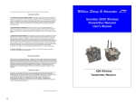
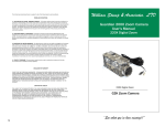
The limited warranty stated herein is subject to all of the following terms and conditions.
William Stump & Associates, Ltd.
TERMS AND CONDITIONS
1. NOTIFICATION OF CLAIMS: WARRANTY SERVICE: If Purchaser believes that the product is defective in
material or workmanship, then written notice with an explanation of the claim shall be given promptly by
Purchaser to the Manufacturer but all claims for warranty service must be made within the warranty period.
No repair or replacement of any product or part thereof shall extend the warranty period as to the entire
product. The specific warranty on the repaired part only shall be in effect for a period of ninety (90) days
following the repair or replacement of that part or the remaining period of the product parts warranty,
whichever is greater.
2. EXCLUSIVE REMEDY: ACCEPTANCE: Purchaser’s exclusive remedy and the Manufacture’s sole
obligation is to supply all labor necessary to repair any product found to be defective within the warranty
period. Purchaser’s failure to make a claim as provided in paragraph 1 above or continued use of the
product shall constitute an unqualified acceptance of such product and a waiver by Purchaser of all claims
thereto.
Guardian 2000
PIR and Vibration Sensor
User’s Manual
3. EXCEPTIONS TO LIMITED WARRANTY: The Manufacturer shall have no liability or obligation to Purchaser
with respect to any product requiring service during the warranty period which is subjected to any of the
following: abuse, improper use, negligence, accident, modification, failure of the end-user to follow the
operating procedures outlined in the user’s manual, failure of the end-user to follow the maintenance
procedures in the service manual for the product, attempted repair by non-qualified personnel, operation of
the product outside of the published environmental and electrical parameters, or if security seal has been
defaced, altered, or removed. The Manufacturer also excludes from warranty coverage products located
outside the United States, and consumable items such as fuses and batteries. Items not manufactured by
Backgrounds Unlimited, Inc but included in system bought by Purchaser are limited to original
manufacturer’s warranty and will be repaired by Backgrounds Unlimited, Inc. on cost of material basis.
4. PROOF OF PURCHASE: The purchaser’s dated invoice must be retained as evidence of the date
of purchase and to establish warranty eligibility.
DISCLAIMER OF WARRANTY
EXCEPT FOR THE FOREGOING WARRANTIES, THE MANUFACTURER HEREBY DISCLAIMS AND EXCLUDES ALL
OTHER WARRANTIES, EXPRESS OR IMPLIED, INCLUDING, BUT NOT LIMITED TO ANY AND/OR ALL IMPLIED
WARRANTIES OF MERCHANTABILITY, FITNESS FOR A PARTICULAR PURPOSE AND/OR ANY WARRANTY WITH
REGARD TO ANY CLAIM OF INFRINGEMENT THAT MAY BE PROVIDED IN SECTION 2-312(3) OF THE UNIFORM
COMMERCIAL CODE AND/OR ANY OTHER COMPARABLE STATE STATUE. THE MANUFACTURER HEREBY
DISCLAIMS ANY REPRESENTATIONS OR WARRANTY THAT THE PRODUCT IS COMPATIBLE WITH ANY
COMBINATION OF NON-MANUFACTURER’S PRODUCTS PURCHASER MAY CHOOSE TO CONNECT TO THE
PRODUCT.
LIMITATION OF LIABILITY
THE LIABILITY OF THE MANUFACTURER, IF ANY, AND PURCHASER’S SOLE AND EXCLUSIVE REMEDY FOR
DAMAGES FOR ANY CLAIM OF ANY KIND WHATSOEVER, REGARDLESS OF THE LEGAL THEORY AND
WHETHER ARISING IN TORT OR CONTRACT, SHALL NOT BE GREATER THAN THE ACTUAL PURCHASE PRICE
OF THE PRODUCT WITH RESPECT TO WHICH SUCH CLAIM IS MADE. IN NO EVENT SHALL THE
MANUFACTURER BE LIABLE TO PURCHASER FOR ANY SPECIAL, INDIRECT, INCIDENTAL, OR
CONSEQUENTIAL DAMAGES OF ANY KIND INCLUDING, BUT NOT LIMITED TO, COMPENSATION,
REIMBURSEMENT OR DAMAGES ON ACCOUNT OF THE LOSS OF PRESENT OR PROSPECTIVE PROFITS OR
FOR ANY OTHER REASON WHATSOEVER.
G2K PIR and Vibration Sensor
“See what you’ve been missing!!”
5
INTRODUCTION
Testing the Sensors
Congratulations, and thank you for purchasing the
Guardian 2000 PIR and Vibration Sensor. This
sensor automatically integrates with your existing
Guardian 2000 video system and is manufactured
using stringent standards from customer input.
Features include:
•
•
•
•
•
•
•
Weatherproof housings
Dual Infrared pyroelectric sensor
“AA” battery operation
Indoor and outdoor operation
Up to 100 ft range depending on sensitivity
setting and ambient temperature
As you read through this manual, please keep in mind
your system has been rigorously inspected for utmost
quality assurance prior to shipment.
About the PIR Sensor
The PIR Sensor incorporates a pyroelectric
sensor and a radio frequency transmitter to
activate your Guardian 2000. The result is an
extremely reliable sensor designed to
significantly reduce “false” activations. Being
able to bury the transmitter housing makes this
an almost truly invisible sensor. The flexible
head also makes it extremely easy to deploy
under almost any condition.
i
•
Testing the sensor during deployment is crucial for success.
Once the initial setup has been made, test the sensor before leaving the target area.
Conduct several walk-through tests in the target area to determine proper sensor placement.
Deployment
PIR Sensor
•
•
•
•
•
•
When using the PIR sensor to monitor a trail, best results
are achieved when placing the head about waist level.
The PIR sensor should be solidly mounted to avoid excessive movement. Therefore, it is equipped with a small black
clamp on the head to assist attaching to a solid object.
Other devices such as wire ties, zip-ties, hook and loop type
fasteners and even natural vines can be used.
The PIR sensor has two sensing elements arranged to cancel out false alarms from vibration, temperature changes
and sunlight.
The sensor also has an added filter window which is most
sensitive to human body radiation, detecting movement up
to 100 ft. depending on sensitivity settings.
With the long range 1 1/4” diameter fresnel head field of
view is approximately 10 degrees.
Vibration Sensor
•
•
•
When using the vibration sensor to monitor a dump site,
best results are achieved when attaching the head to a
stick and placing it in the dump pile.
If monitoring a gate, the sensor can be mounted to a post.
When the gate is opened or tampered with the motion will
send a signal to begin recording.
While monitoring a road, attach a high strength fishing line
(50lb braided wire recommended). Secure the fishing line
at high tension 1” above ground. Any object passing the
line will activate recording.
4
5. Now you are ready to test it with the Guardian 2000. Place
your Guardian 2000 into PGM mode. Test the PIR sensor
again and the Guardian 2000 will activate and begin recording.
Figure 3
Vibration Sensor
1. Obtain the hand-held control module provided with your
Guardian 2000 and turn it on with the alarm feature activated. Maintain a close distance in order to hear the audible alarm.
2. The vibration head contains two magnets that can be used
to attach to a metal surface. The head can also be secured
with the two mounting screw holes.
3. Connect the four pin head to the housing. The sensor will
be ready for immediate use.
4. Conduct a test of the vibration sensor by walking near the
head. The vibration sensor will transmit an alarm signal to
the handheld control module.
5. Now you are ready to test it with the Guardian 2000. Place
your Guardian 2000 into PGM mode. Test the PIR sensor
again and the Guardian 2000 will activate and begin recording.
3
Table of Contents
General . . . . . . . . . .
1
Pre-Operation . . . . . . .
1
Setup . . . . . . . . . . .
1
Testing . . . . . . . . . . .
2
Deployment . . . . . . . .
3
Warranty Information . . .
5
ii
Pre-Operation
General
The PIR Sensor uses infrared radiation detection for operation.
When an object such as a person, animal, or vehicle passes in
front of the sensing head, a transmitter sends a signal to the
Guardian 2000 record unit for activation. The PIR sensor
comes standard with a long range head containing a fresnel lens
which allows for the maximum detection range, up to 100 ft depending on sensitivity settings (See Figure 1). The weatherproof
housing and flexible head enable quick and effortless installations.
PIR and Vibration Sensor
1. Connect the antenna to the top of the housing.
2. Remove (4) screws from the lid of the transmitter housing.
3. Set the sensitivity by turning the knob. The far left allows
for the least sensitive while the far right is a maximum setting. (Only PIR Sensor, See Figure 2)
4. Insert (4) “AA” alkaline batteries into the transmitter’s battery holder. To turn power off, simply remove the batteries
from the battery holder.
Sensitivity
Adjustment
Left = Least
Sensitive
Right = Most
Sensitive
Figure 2
Setup
PIR Sensor
Figure 1
1
1. Obtain the hand-held control module provided with your
Guardian 2000 and turn it on with the alarm feature activated. Maintain a close distance in order to hear the audible alarm.
2. Secure the PIR head to a solid surface pointing towards
your activation area. To detect horizontal movement, ensure that the back of the head has the cut outs on the left
and right sides, with the slots straight up and down (See
Figure 3).
3. Connect the four pin head to the housing. The sensor will
stabilize after 1 minute.
4. Conduct a test of the PIR by walking or by placing your
hand in front of the lens. The PIR sensor will transmit an
alarm signal to the handheld control module.
2