1
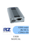
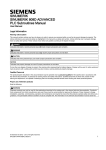
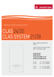
ES90U
UMTS (3G)
EDGE/GPRS
GSM modem
USER
MANUAL
GSM modem iRZ ES90U
User Manual
Contents
Safety Requirements ..................................................................................................................................................... 3
1.
General Information ............................................................................................................................................. 4
1.1.
Purpose of the Device ................................................................................................................................. 4
1.2.
Configuration.............................................................................................................................................. 4
1.3.
Parameters .................................................................................................................................................. 4
1.4.
Exterior Appearance ................................................................................................................................... 6
1.5.
Interfaces .................................................................................................................................................... 7
1.6.
Modem Status Indication........................................................................................................................... 10
2.
Connection, Setting Up and Control ................................................................................................................... 11
2.1.
Connection, Operation Mode..................................................................................................................... 11
2.2.
Setting Up UMTS/EDGE/GPRS ............................................................................................................... 11
2.3.
Control, Restarting and Power Off............................................................................................................. 11
2.4.
Menu Mode .............................................................................................................................................. 13
2.5.
Programming mode................................................................................................................................... 15
3.
Emergency Situations......................................................................................................................................... 19
3.1.
Emergency 1 (input voltage invalid).......................................................................................................... 19
3.2.
Emergency 2 (module power supply invalid) ............................................................................................. 19
3.3.
Emergency 3 (GSM module not started).................................................................................................... 19
2
GSM modem iRZ ES90U
User Manual
Safety Requirements
Restrictions for the usage of the device in the vicinity of other electronic devices:
· turn off the modem in hospitals or in the vicinity of medical equipment (e.g.
cardiostimulators, hearing aids). It can cause interference for medical equipment;
· turn off the terminal in aircrafts. Take measures against accidental activation;
· turn off the modem in the vicinity of gas-filling stations, chemical enterprises, blasting
work places. It can cause interference to technical devices;
· at a short range the modem may cause harmful interference to TV and radio receivers.
Prevent the modem from dust and moisture.
Improper use deprives you of all warranty claims.
3
GSM modem iRZ ES90U
User Manual
1. General Information
1.1. Purpose of the Device
The GSM modem iRZ ES90U is an industrial GSM modem designed for broadband reception
and transmission of data via the GSM channel (3G). It is excellently adjusted both for mobile
Internet access and for industrial applications — telemetry, wireless data collection from sensors,
remote viewing, monitoring and signaling.
The modem is equipped with a set of watchdog timers. The control is performed by means of
standard AT-commands. The modem is equipped with LED indicators to track the connection status
and to display any emergency situation. Modem iRZ ES90U (3G) which is an analog modem, GSM
iRZ ES90i (3G). The only difference - the ability to communicate with the modem as for USB, and
via COM-port.
1.2. Configuration
Complete set of the GSM modem iRZ ES90U:
· terminal ES90U,
· label,
· factory box.
1.3. Parameters
Basic parameters:
· frequency ranges:
o 850/900/1900/2100 MGz for UMTS,
o 850/900/1900/2100 MGz for HSUPA /HSDPA,
o 850/900/1800/1900 MGz for EDGE/GPRS/GSM;
· power output:
o 33 dBm (class 4 for EGSM/GPRS 850/900),
o 30 dBm (class 1 for GSM/GPRS 1800/1900),
o 24 dBm (class 3 for UMTS 850/900/1900/2100);
· UMTS 3GPP Release 6:
o HSPA data receive rate 7.2 Mbit/s, transmission rate 2 Mbit/s;
o PS data receive rate – 384 kbps, transmission rate 384 kbps;
o CS data receive rate – 64 kbps, transmission rate 64 kbps;
· EDGE class 12, data receive rate – 236.8 kbps, transmission rate 236.8 kbps;
· GPRS class 12, data receive rate – 53,6 kbps, transmission rate 53.6 kbps;
· MC class B;
· CSD up to 14.4 kbps;
· USSD;
· SMS: MT, MO, Text and PDU.
4
GSM modem iRZ ES90U
User Manual
Electric power supply:
· power supply voltage 9 to 27 V;
· absorbed current:
o with power supply voltage +12 V – 400mA;
o with power supply voltage +24 V – 200mA.
Physical parameters:
· size, max 76х53х31 mm;
· weight, max 110 g.;
· operating-temperature range -20°С to +60°С,
· storage temperature range -40°С to +85°С.
Interfaces:
· DB9 RS-232,
· USB-B USB 2.0,
· SMA antenna connector,
· RJ11 power supply.
5
GSM modem iRZ ES90U
User Manual
1.4. Exterior Appearance
The modem ES90U is a compact device designed in solid and lightweight aluminum housing.
The exterior appearance is represented on Fig. 1.4.1 and Fig.1.4.2.
2
3
4
5
1
Fig.1.4.1 Front view
7
8
6
Fig.1.4.2 Back view
On the figures 1.4.1 and 1.4.2 the digits signify the following:
1. SIM card tray,
2. SIM card tray extractor
3. Status LED indicator (green),
4. Emergency LED indicator (red),
5. Connector SMA for GSM antenna connection,
6. Connector RJ11 for power supply connection,
7. Connector DB9 (RS232) for data cable connection,
8. Connector USB type B for data cable connection.
6
GSM modem iRZ ES90U
User Manual
1.5. Interfaces
1.5.1. Connector DB9 for Data Cable Connection
The connector is used to connect to the control device, exchange protocol RS232. The time rate
on default is 115200 bps, 8-N-1. The exterior appearance of the connector is represented on Fig.1.5.1
5
4
9
3
2
8
7
1
6
Fig.1.5.1
Table 2.5.1 Purpose of the connector pins.
Contact
Signal
Direction
1
DCD
Modem-PC
2
RXD
Modem-PC
3
TXD
PC-Modem
4
DTR
PC-Modem
5
GND
general
6
DSR
7
RTS
PC-Modem
8
CTS
Modem-PC
9
RI
Modem-PC
Purpose
Availability of carrier wave
Data reception
Data transmission
Availability of data reception
System housing
not used
Request for transmission
Availability of transmission
Call signal
7
GSM modem iRZ ES90U
User Manual
1.5.2. Connector RJ11 for Power Supply Connection
The connector is used for power supply connection and restarting of the module. External
appearance of the connector is represented on Fig.1.5.2.
6
5
4
3
2
1
Fig.1.5.2
Table 2.5.2 Purpose of the power supply connector pins.
Contact
Signal
Purpose
1
GND
system housing
2
not used
3
not used
4
RESET
module restarting
5
not used
6
+ 12V
Positive pole of DC supply voltage.
8
GSM modem iRZ ES90U
User Manual
1.5.3. Connector USB Type B for Data Cable Connection
The connector is used to connect the interface USB 2.0 to the control device. The exterior
appearance of the connector is represented on Fig. 1.5.3.
2
1
3
4
Fig.1.5.3
Table 2.5.3 Purpose of the USB connector pins.
Contact
Signal
1
V BUS
Not used
2
D−
Data transmission
3
D+
Data transmission
4
GND
System housing
Purpose
9
GSM modem iRZ ES90U
User Manual
1.6. Modem Status Indication
Two LEDs are used to indicate the operation mode (connection status) or any emergency
situation.
Table 1.6.1 Operation mode and connection status indication (green LED)
Conventional displaying of
Operation mode
Indication Mode
indication
Turned off
Modem is turned off or there is an
●
emergency situation
600 ms on / 600 ms off
○○○○○●●●●●
Modem is not registered in the network
75 ms on / 3 s off
○●●●●●●●●●
Modem is registered in the network
GPRS connection is installed
75 ms on / 75 ms off / 75
○●○●●●●●●●●●
ms on / 3 s off
500 ms on / 50 ms off
○○○○○●
Data transmission is underway
250 ms on / 250 ms off
○○○●●●
Programming mode, menu mode
Table 1.6.2 Emergency situation indication (red LED)
Conventional displaying of
Indication Mode
indication
Turned on continuously
○
0.5 s on / 0.5 s off
○○○○○●●●●●
0.25 s on / 0.25 s off /
○○○●●●○○○●●●●●●●
0.25 s on / 1 s off
For description of emergencies see Section 3 (page 19)
10
Emergency description
Input voltage invalid
Power supply of the module invalid
GSM module not started
GSM modem iRZ ES90U
User Manual
2. Connection, Setting Up and Control
2.1. Connection, Operation Mode
The application field of the modem can be divided into two nominal parts: personal computer
connection for Internet access and industrial use.
In both cases the connection sequence is the same.
Before feeding the power supply you need to install the SIM card in the modem (SIM card must
be enabled). To do this, you need:
· to extract the SIM tray by pressing the SIM tray extract button (Fig. 2.4.1);
· to install the SIM card in the SIM tray;
· to insert the SIM tray into the modem.
No strong physical efforts must be applied while installing the SIM card.
Connect the GSM antenna and the commutation cable (RS232 or USB) to the antenna connector
(Fig.2.4.2). Thereupon you need to feed power supply to the modem through the connector RJ11
(Fig.2.4.1).
Note: GSM antenna, commutation cables and electrical power unit are not included in the
complete set configuration.
After the power supply feeding, the operating microcontroller analyses the availability of the
SIM tray. With the SIM tray available, the modem jumps to the operation mode: checks the input
voltage, commutates the UART pins of the GSM module to the external connector DB9, and
activates the GSM module. Then the registration proceeds, the “Status” LED flashes frequently.
After the registration is completed, the indicator flashes less frequently (Table 2.6.1). In this mode
the GSM module controls the flashing.
2.2. UMTS/EDGE/GPRS Setting Up
Connection and setting up of the modem for the Internet access from a personal computer is
carried out as that from a standard modem. If the USB interface is used, you need to install the
driver. The necessary driver can be downloaded on the site (www.radiofid.ru). In case of any
difficulties refer to the guidelines on the site, the Support section.
For industrial applications the modem control is performed by standard AT commands.
2.3. Control, Restarting and Power Off
The modem is controlled by standard AT commands. The description of the AT commands can
be downloaded on the site www.radiofid.ru .
The modem can be restarted in the following ways:
· by eight jumpings of the DTR line of the COM port into passive state (DTR < -2V),
duration of pulses and the pauses between the pulses must lie within the range 100-500
ms;
· by feeding a positive pulse (10 V to 20 V) as long as 50 ms to 200 ms to the 4th power
supply connector pin (Section 1.5.2);
· by temporary power-off.
11
GSM modem iRZ ES90U
User Manual
The modem can be powered off only by supply disconnection. The modem settings are saved
when the modem is powered off only provided it has been done by an AT command.
12
GSM modem iRZ ES90U
User Manual
2.4. Menu Mode
The menu mode is designed to change the modem parameters and view the statistics. In this
mode the GSM module power supply is disconnected, after the exit the modem automatically jumps
to the operation mode. You can jump to the menu mode from the operation mode by extracting the
SIM tray. Before jumping into the menu mode, connect the modem to the computer through the
connector DB9, start Hyper Terminal (time rate is 115200 bpc, 8-N-1) or a similar program.
If you have entered the menu mode successfully, the LED indicator will flash frequently (see
Table 1.6.1), the main menu will be displayed in Hyper Terminal:
Menu_mode:
Variant XX
<P1> View statistics
<P2> WD interval = XXX hh (или “OFF”)
<PC> Power control
<PR> Clear statistic,
Where Variant XX is the weaving version.
The characters <…> signify the control commands. Input of the command gets underway after
clicking “Enter”. In case of incorrect input, “ERROR” is indicated. There is no difference between
the entered uppercase and lowercase characters.
After input of the command “P1” you jump to the statistics viewing menu:
Power_Modem = XX…X
Bad_Power_Modem = XX…X
Power_Module = XX…X
Bad_Power_Module = XX…X
Start_Module = XX…X
Bad_Start_Module = XX…X
Deadlock_of_module = XX…X
Reset = XX…X
When the modem is used, the following situations are automatically saved:
Power_Modem – number of modem connexions,
Bad_Power_Modem – number of power supply deviations of the modem from the allowed
value,
Power_Module – number of power supply feedings to the GSM module,
Bad_Power_Module - number of power supply deviations of the GSM module from the allowed
value,
Start_Module – number of successful GSM module starts,
Bad_Start_Module – number of situations where the GSM module did not start,
Deadlock_of_module – number of the GSM module deadlocks,
Reset – number of restartings.
After the statistics output, you will jump to the main menu.
After input of the command “P2” you will jump to the WD menu:
WD interwal = <hour (00 - WD off, max - 255)>
<Q> Quit
WD interval =
In order to change the restarting interval, enter a number from 0 to 255 (input is after clicking
“Enter”). The restarting interval is specified in hours. If you need to disable this function, enter 0.
13
GSM modem iRZ ES90U
User Manual
You should consider that after expiration of the specified time interval the modem will be restarted
unconditionally. In case of incorrect input, the modem will indicate “ERROR” and display the WD
menu again. If the restarting interval is entered successfully, or if the “Q” command is issued, you
will jump to the main menu.
After input of the “PC” command you can view the input supply voltage and the module supply
voltage (measurement accuracy 5%):
P0WER Uin=12.0 Umd=3.3
where Uin is input voltage in volts, Umd is voltage on the GSM module in volts.
After the display you will jump to the main menu.
After input of the “PR” command you will jump to the statistics clearing menu:
Clear statistic?
<Yes> Yes
<Q> Quit
The collected statistics is cleared by the command “YES”. In case of incorrect input, the modem
will indicate “ERROR” and represent the statistics clearing menu again. If the command <Q> is
entered or issued successfully, you will jump to the main menu.
After input of the command “M” the main menu will load again.
Exit from the menu mode occurs after installation of the SIM tray, the modem jumps to the
operation mode.
14
GSM modem iRZ ES90U
User Manual
2.5. Programming Mode
The programming mode is used to change / update the software of the modem microcontroller.
The software is updated via the interface RS232 using the program “ mprog2.exe ”. You can
download the program by the reference: http://www.radiofid.ru/upload_data/drivers/mprog2.rar
To change the weaving, take the following steps:
1. Start the program “mprog2.exe”. The program window will appear (Fig.1).
Fig.1
2. Close the programs which use the port to which the modem is going to be connected.
Click the button “Scan” in the program window. Select the number of the COM-port to
which the modem is going to be connected (Fig.2)
Fig.2
15
GSM modem iRZ ES90U
User Manual
3. Connect the modem (without the SIM tray) to the computer. Feed the power supply to
the modem. The modem is to jump to the programming mode. The LED indicator
(green) flashing is 250 ms on/250 ms off.
Click the button “Open”. Herewith the model of the device is to be displayed (Fig.3).
Fig.3
4. Select the new weaving file by clicking the “File” button. The window (Fig.4) will
appear.
Fig.4
16
GSM modem iRZ ES90U
User Manual
5. Select the new weaving file. Click “Open”. If the file is loaded successfully, the screen
similar to Fig.5 will be displayed in the window.
Fig.5
6. Click “Record”. If the weaving has been changed successfully, the screen similar to
Fig.6 will be displayed.
Fig.6
17
GSM modem iRZ ES90U
User Manual
7. Click the start button. Herewith the modem will escape from the programming mode,
the COM port will close (Fig.7).
Fig.7
8. Close the program. Insert the SIM tray into the modem.
The weaving change is completed. The modem will jump to the operation mode.
18
GSM modem iRZ ES90U
User Manual
3. Emergency Situations
To simplify the use of the modem, tracking of emergencies is provided.
3.1. Emergency 1 (input voltage invalid)
Emergency 1 occurs in case of deviation of the input power supply voltage from the allowed
value. In such case the modem stops the operation: disconnects the GSM module power supply. It
signals with the red LED about the emergency situation (turned on continuously). Escaping from the
emergency situation is possible only after restoring of the input voltage.
3.2. Emergency 2 (module power supply invalid)
Emergency 2 arises in the event of deviation of the power supply voltage of the GSM module
from the allowed value. In such case the modem stops the operation: disconnects the GSM module
power supply. It signals with the red LED about the emergency situation (0.5 s on / 0.5 s off).
Escaping from the emergency situation is possible only after restoring of the power supply voltage
of the module within 10 seconds from the time when the emergency situation occurred. If the power
supply voltage of the module stays incorrect within 10 seconds (with correct input voltage), the
modem jumps to the standby mode – the module power supply is disconnected, the emergency
indication persists. Escaping from the standby mode is possible only after full disconnection of
power supply.
In case of any repeated emergency after restarting of the modem, the modem is to be repaired.
3.3. Emergency 3 (GSM module not started)
Emergency 3 occurs in the event where the GSM module is not started. Red LED signaling about
the emergency situation: 0.25 s on / 0.25 s off / 0.25 s on / 1 s off. Escaping from the emergency
situation is possible only after successful start of the GSM module. In case of 10 consecutive failed
attempts to start the module (15 seconds), the modem jumps to the standby mode – the module
power supply is disconnected, the emergency indication persists. Escaping from the standby mode is
possible only with full disconnection of the power supply.
In case of any repeated emergency after restarting of the modem, the modem is to be repaired.
19