1
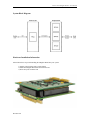
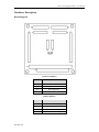
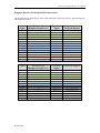
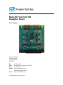
Multi-IO FreeForm/104 Daughter Board User Manual Connect Tech Inc. 42 Arrow Road Guelph, Ontario N1K 1S6 Tel: Toll: Fax: Email: Web: 519-836-1291 800-426-8979 (North America only) 519-836-4878 [email protected] [email protected] www.connecttech.com CTIM-00434 Revision 0.01 January 28, 2015 Connect Tech Daughter Board - User Manual Table of Contents Customer Support Overview .......................................................................................................................... 3 Contact Information........................................................................................................................................ 3 Limited Lifetime Warranty............................................................................................................................. 4 Copyright Notice ............................................................................................................................................ 4 Trademark Acknowledgment ......................................................................................................................... 4 Revision History ............................................................................................................................................. 4 Introduction .................................................................................................................................................... 5 Features ..................................................................................................................................................................... 5 Specifications ............................................................................................................................................................ 6 System Block Diagram ............................................................................................................................................. 7 Hardware Installation Information ............................................................................................................................ 7 Hardware Description ..................................................................................................................................... 8 Board Diagram .......................................................................................................................................................... 8 Daughter Board to FreeForm/104 Pin Interconnect .................................................................................................. 9 Output Pin Reference .............................................................................................................................................. 10 Port 1.............................................................................................................................................................10 Port 2.............................................................................................................................................................11 Mode Selection Jumper Reference .......................................................................................................................... 12 Jumper Selection Key for Port Modes ..........................................................................................................12 Clock Bias / Termination Jumper Selections ................................................................................................12 Clock Combination Jumper Selections .........................................................................................................13 Control Line Jumper Reference .............................................................................................................................. 14 RS-232 Clock Signals ...................................................................................................................................14 RS-485 Clock Signals ...................................................................................................................................15 Revision 0.01 Connect Tech Daughter Board - User Manual Customer Support Overview If you experience difficulties after reading the manual and/or using the product, contact the Connect Tech reseller from which you purchased the product. In most cases the reseller can help you with product installation and difficulties. In the event that the reseller is unable to resolve your problem, our highly qualified support staff can assist you. Our support section is available 24 hours a day, 7 days a week on our website at: www.connecttech.com/sub/support/support.asp. See the contact information section below for more information on how to contact us directly. Our technical support is always free. Contact Information We offer three ways for you to contact us: Mail/Courier You may contact us by letter at: Connect Tech Inc. Technical Support 42 Arrow Road Guelph, Ontario Canada N1K 1S6 Email/Internet You may contact us through the Internet. Our email and URL addresses on the Internet are: [email protected] [email protected] www.connecttech.com Note: Please go to the Download Zone or the Knowledge Database in the Support Center on the Connect Tech website for product manuals, installation guides, device driver software and technical tips. Submit your technical support questions to our customer support engineers via the Support Center on the Connect Tech website. Telephone/Facsimile Technical Support representatives are ready to answer your call Monday through Friday, from 8:30 a.m. to 5:00 p.m. Eastern Standard Time. Our numbers for calls are: Toll Free: 800-426-8979 (North America only) Telephone: 519-836-1291 (Live assistance available 8:30 a.m. to 5:00 p.m. EST, Monday to Friday) Facsimile: 519-836-4878 (on-line 24 hours) Revision 0.01 Connect Tech Daughter Board - User Manual Limited Lifetime Warranty Connect Tech Inc. provides a Lifetime Warranty for all Connect Tech Inc. products. Should this product, in Connect Tech Inc.'s opinion, fail to be in good working order during the warranty period, Connect Tech Inc. will, at its option, repair or replace this product at no charge, provided that the product has not been subjected to abuse, misuse, accident, disaster or non-Connect Tech Inc. authorized modification or repair. You may obtain warranty service by delivering this product to an authorized Connect Tech Inc. business partner or to Connect Tech Inc. along with proof of purchase. Product returned to Connect Tech Inc. must be pre-authorized by Connect Tech Inc. with an RMA (Return Material Authorization) number marked on the outside of the package and sent prepaid, insured and packaged for safe shipment. Connect Tech Inc. will return this product by prepaid ground shipment service. The Connect Tech Inc. Lifetime Warranty is defined as the serviceable life of the product. This is defined as the period during which all components are available. Should the product prove to be irreparable, Connect Tech Inc. reserves the right to substitute an equivalent product if available or to retract Lifetime Warranty if no replacement is available. The above warranty is the only warranty authorized by Connect Tech Inc. Under no circumstances will Connect Tech Inc. be liable in any way for any damages, including any lost profits, lost savings or other incidental or consequential damages arising out of the use of, or inability to use, such product. Copyright Notice The information contained in this document is subject to change without notice. Connect Tech Inc. shall not be liable for errors contained herein or for incidental consequential damages in connection with the furnishing, performance, or use of this material. This document contains proprietary information that is protected by copyright. All rights are reserved. No part of this document may be photocopied, reproduced, or translated to another language without the prior written consent of Connect Tech, Inc. Copyright 1997 - 2011 by Connect Tech, Inc. Trademark Acknowledgment Connect Tech, Inc. acknowledges all trademarks, registered trademarks and/or copyrights referred to in this document as the property of their respective owners. Not listing all possible trademarks or copyright acknowledgments does not constitute a lack of acknowledgment to the rightful owners of the trademarks and copyrights mentioned in this document. Revision History Revision 0.00 – June 15, 2012 Revision 0.01 – Jan. 28, 2015 Revision 0.01 Connect Tech Daughter Board - User Manual Introduction The Daughter Board is an adapter for Connect Tech’s FreeForm/104 FPGA development board that enables users to capture and process synchronous and asynchronous RS232 or RS485/RS422 serial data with customizable FPGA implementations. When used with a FreeForm/104 FPGA development board, the Daughter Board allows for easy and rapid design changes at run time, which makes it ideal for high speed, compute intensive, reconfigurable applications. Connecting directly to the Digital I/O headers on the FreeForm/104, the Daughter Board also includes a PC/104 pass-through connector to allow the board to sit in-stack with the FreeForm/104 board. Features Integration with the FreeForm/104 Xilinx Spartan-3E FPGA enables UART design and data capture customization Two switchable RS-232, RS-422 or RS-485 channels, configurable to be fully synchronous or asynchronous Pass-through PC/104 connector allows the Daughter Board to stack with the FreeForm/104 parent-board Revision 0.01 Connect Tech Daughter Board - User Manual Specifications Number of Ports 2 Electrical Interface Synchronous RS-232, RS-422, RS-485 Control Signals TxD, RxD, DTR, RTS, CTS, DCD, TxClk, RxClk Connectors PC/104 pass-through 2x50 pin connector to connect to FreeForm 2x26 pin header connectors (optional ribbon cables with female 26 pin IDC to female DB-26 connectors available) Baud Rate RS-232: Up to 1 Mbps Rs-422/RS-485: Up to 10 Mbps Dimensions Length: 14.699 cm/5.750” / 9.5885cm/3.775” Height: 11.049 cm/4.350” / 9.017cm/3.55” Temperature 0°C to 70°C (-32°F to 159°F) Bus PC/104 Software Compatibility Windows, Linux, QNX System Requirements Varies by configuration Regulatory Approvals FCC Class A EN50082-2 ICES-003 Class A EN550022 Class A EN55024 Warranty and Support Revision 0.01 Lifetime warranty and free technical support Connect Tech Daughter Board - User Manual System Block Diagram Hardware Installation Information Please follow these steps with installing the Daughter Board into your system. 1) Ensure your FreeForm/104 is powered OFF 2) Install the Daughter Board onto the FreeForm/104 3) Power ON your FreeForm/104 Revision 0.01 Connect Tech Daughter Board - User Manual Hardware Description Board Diagram Connector Summary Location Connection P1, P4 FreeForm/104 Header Connectors P2, P3 Pass-through PC/104 Connectors P5 Port 2 Serial I/O P6 Port 1 Serial I/O Jumper Summary Revision 0.01 Location Connection J1 Port 1 Mode Selection Jumpers J2 Port 2 Mode Selection Jumpers P8 Port 1 Control Line Jumpers P9 Port 2 Control Line Jumpers Connect Tech Daughter Board - User Manual Daughter Board to FreeForm/104 Pin Interconnect The Daughter Board connects directly to the Digital I/O headers on the FreeForm/104. The following table lists the pin interconnect: Signal P8 Header Pin (Daughter Board Port 1) Freeform Signal FreeForm Register TX1 RTS1 DTR1 1 3 5 DIO_2A7 DIO_2A6 DIO_2A5 8255 2 Port C I/O 8255 2 Port C I/O 8255 2 Port C I/O RX1 CTS1 DSR1 DCD1 RI1 2 4 6 8 10 DIO_3A7 DIO_3A6 DIO_3A5 DIO_3A4 DIO_3A3 8255 3 Port C I/O 8255 3 Port C I/O 8255 3 Port C I/O 8255 3 Port C I/O 8255 3 Port C I/O TXC1 17 DIO_2B7 8255 2 Port B I/O RXC1 18 DIO_3B7 8255 3 Port B I/O Signal P6 Header Pin (Daughter Board Port 2) Freeform Signal FreeForm Register TX2 RTS2 DTR2 1 3 5 DIO_0C7 DIO_0C6 DIO_0C5 8255 0 Port A I/O 8255 0 Port A I/O 8255 0 Port A I/O RX2 CTS2 DSR2 DCD2 RI2 2 4 6 8 10 DIO_1C7 DIO_1C6 DIO_1C5 DIO_1C4 DIO_1C3 8255 1 Port A I/O 8255 1 Port A I/O 8255 1 Port A I/O 8255 1 Port A I/O 8255 1 Port A I/O TXC2 17 DIO_0B7 8255 0 Port B I/O RXC2 18 DIO_1B7 8255 1 Port B I/O Revision 0.01 Connect Tech Daughter Board - User Manual Output Pin Reference Port 1 Pin 1 2 3 4 5 6 7 8 9 10 11 12 13 14 15 16 17 18 19 20 21 22 23 24 25 26 Revision 0.01 Description GND TX1+ TX1TXClRX1RX1+ RTS1RXClCTS1DSR1RTS1+ GND DTR1DCD1RXCl+ TXCl+ RI1CTS1+ Connect Tech Daughter Board - User Manual Port 2 Pin 1 2 3 4 5 6 7 8 9 10 11 12 13 14 15 16 17 18 19 20 21 22 23 24 25 26 Revision 0.01 Description GND TX2+ TX2TX2lRX2RX2+ RTS2RXC2CTS2DSR2RTS2+ GND DTR2DCD2RXC2+ TXC2+ RI2CTS2+ Connect Tech Daughter Board - User Manual Mode Selection Jumper Reference The following diagram shows the mode selection jumper locations for both Port 1 and Port 2. Jumpers are placed vertically, connecting the two pins located directly above the corresponding letter: Jumper Selection Key for Port Modes A Out In In In In B Out Out In In Out C Out Out Out In In Mode RS232 RS485 FD RS485 MDS (TX Control) RS485HD (TX/RX Control) Undefined (RX Control) *Note: this jumper solution/layout was taken from the BlueStorm Family Clock Bias / Termination Jumper Selections D X X Out In G Out In Out In Revision 0.01 E X X Out In H Out In Out In F Out In X X I Out Out In In Result No Tx Termination Tx Terminated No Rx Bias/Termination Rx Bias/Termination Enabled J Out Out In In Result No Termination/Bias Tx Clock Termination/Bias Rx Clock Termination/Bias Rx/Tx Clock Termination/Bias Connect Tech Daughter Board - User Manual Clock Combination Jumper Selections K In Out L In Out Result Clocks are Combined Clocks are Separate *Note: when combining clocks, it is best to disable one of the transceivers Revision 0.01 Connect Tech Daughter Board - User Manual Control Line Jumper Reference The following diagram shows the control line jumper locations for both Port 1 and Port 2 (P8 and P9 respectively). Jumpers are placed horizontally, connecting the two pins located directly beside the corresponding letter: RS-232 Clock Signals SP3220 transceivers are used to accomplish the bidirectional signalling needed. These are single driver, receiver transceivers with the ability to individually tri-state the driver or receiver or both. This allows for shared signal lines, with the intention that only one section of the part is active at a time. The Shutdown and Enable pins on the 3220 are used to create the tri-stating: SH 0 0 1 1 EN 0 1 0 1 TX-Out Tri-State Tri-State Active Active RX-OUT Active Tri-State Active Tri-State Result Receiver Only Both Disabled Both Enabled (Avoid) Driver Only Because the daughterboard is configured to have both driver and receiver disabled by default, the SH pin can be used as the Driver enable while the EN pin can be used as the receiver enable. This leaves the following jumper setup: Jumper C D G H Revision 0.01 Result TX Clock as receiver TX Clock as driver RX Clock as receiver RX Clock as driver Connect Tech Daughter Board - User Manual The state where both driver and receiver are enabled should be avoided as the behaviour of the chip is unknown in this state. RS-485 Clock Signals These signals are configured in a similar method to the 232 signals, with the SP491 chips being used. These chips also have individual enables for both the driver and receiver. The receiver enable is active low, while the driver is active high. Like 232, both driver and receiver are defaulted off by the daughter board. This leaves the following jumper setup: Jumper E F I J Revision 0.01 Result TX Clock as receiver TX Clock as driver RX Clock as receiver RX Clock as driver