1
User’s
Manual
Model TB750G
Right Angle Scattered Light
Turbidimeter
IM 12E01A06-01E
R
IM 12E01A06-01E
3rd Edition
i
<INTRODUCTION>
INTRODUCTION
n
Structure of this Manual
This manual describes the specifications, installation, operation, maintenance, and troubleshooting
for the TB750G Right Angle Scattered Light Turbidimeter. To use this instrument correctly, read this
manual thoroughly.
n
Specification Check
When the instrument arrives, unpack the package with care and check that the instrument has not
been damaged during transportation. Please check that the product received meet the specified
specifications by confirming the model code indicated on the nameplate. For details of the model
code, refer to Section 2.4.1 on page 2-7.
n
Before Measurement
The TB750G turbidimeter is preset with defaults prior factory shipment. Before measurement, verify
that these factory default settings meet the operating conditions and if necessary, reconfigure parameters. For checking the default settings and recording changed parameters, use an Operation Parameter Setting List at the end of this manual.
Media No.IM 12E01A06-01E (CD)
3rd Edition: Mar. 2015 (YK)
All Rights Reserved Copyright © 2005, Yokogawa Electric Corporation
IM 12E01A06-01E
ii
<INTRODUCTION>
Symbols and Notations Used in this Manual
nSymbols
The following symbols are used in this manual.
WARNING
Indicates hazards, e.g., electric shock, which will result in serious personal injury or death if instructions are not followed.
CAUTION
Indicates that damage to software or hardware, or system failures could occur if instructions are not
followed.
NOTE
Instructions needed to understand the operation and functions.
TIP
Supplementary information
SEE ALSO
Related items or pages
nNotations
In this manual, operation keys, display messages, indicators, and LED lamps on the instrument are
denoted in the following manner.
1.
Operation keys are denoted by brackets [ ] – for example:
2.
YES
: [YES] key
Indicators, messages, and numerical data on the display are denoted as follows:
indicator
Status indicator :
Key indicator : YES indicator
Message display: {*WASH}
Data display: {2.05} (when lit), {2.05} (when flashing)
3.
HOLD
Status lamps and modes on the front panel are denoted as follows:
Contact status LED lamp: <S1> (when lit), <S1> (when not lit)
Measurement mode
4.
Flashing state on the display is denoted in light gray – for example:
(Flashing)
IM 12E01A06-01E
: <MEASURE> mode
MEASURE
(Lit)
iii
<INTRODUCTION>
Notice
n
About this Manual
l This manual should be passed on to the end user.
l This manual should be read thoroughly before operating the instrument.
l This manual explains the functions contained in this product, but does not warrant that they will
suit the particular purpose of the user.
l The contents of this manual shall not be reproduced or copied, in part or in whole, without permission.
l The contents of this manual are subject to change without prior notice.
l Every effort has been made to ensure the accuracy in the preparation of this manual. However,
if any errors or omissions are noticed, please contact the nearest Yokogawa representative or
sales office.
n
Protection, Safety, and Modification of the Product
l The safety instructions described in this manual should be strictly observed to ensure safety both
of the product and the system controlled by the product.
l A protection or safety circuit should be installed externally, if needed. Do not attempt to modify or
add such circuit to the inside of the equipment.
n
Limitation of Liability
l Yokogawa grants no warranties other than the express warranty set forth under the warranty
provisions.
l Yokogawa shall not be liable to you or any third party for any damage, including consequential
or incidental damages, arising out of or in connection with the use of this equipment, defects
beyond our knowledge, or any other contingency beyond our control.
IM 12E01A06-01E
iv
<INTRODUCTION>
After-Sales Warranty
l Do not modify the product.
l During the warranty period, for repair under warranty carry or send the product to the local sales
representative or service office. Yokogawa will replace or repair any damaged parts and return
the product to you.
l Before returning a product for repair under warranty, provide us with the model name and serial
number and a description of the problem. Any diagrams or data explaining the problem would
also be appreciated.
l If we replace the product with a new one, we won’t provide you with a repair report.
l Yokogawa warrants the product for the period stated in the pre-purchase quotation. Yokogawa
shall conduct defined warranty service based on its standard. When the customer site is located
outside of the service area, a fee for dispatching the maintenance engineer will be charged to the
customer.
l In the following cases, customer will be charged repair fee regardless of warranty period.
• Failure of components which are out of scope of warranty stated in instruction manual.
• Failure caused by usage of software, hardware or auxiliary equipment, which Yokogawa did
not supply.
• Failure due to improper or insufficient maintenance by user.
• Failure due to misoperation, misuse or modification which Yokogawa does not authorize.
• Failure due to power supply (voltage, frequency) being outside specifications or abnormal.
• Failure caused by any usage out of scope of recommended usage.
• Any damage from fire, earthquake, storms and floods, lightning, disturbances, riots, warfare,
radiation and other natural changes.
l Yokogawa does not warrant conformance with the specific application at the user site. Yokogawa
will not bear direct/indirect responsibility for damage due to a specific application.
l Yokogawa will not bear responsibility when the user configures the product into systems or
resells the product.
l Maintenance service and supplying repair parts will be covered for five years after the production
ends. For repair for this product, please contact the nearest sales office described in this instruction manual.
IM 12E01A06-01E
<CONTENTS>
Toc-1
Model TB750G
Right Angle Scattered Light Turbidimeter
IM 12E01A06-01E 3rd Edition
CONTENTS
INTRODUCTION....................................................................................................i
Symbols and Notations Used in this Manual...................................................ii
Notice...................................................................................................................iii
After-Sales Warranty..........................................................................................iv
1.OVERVIEW................................................................................................. 1-1
1.1
Measurement Principle..................................................................................... 1-2
1.2
Turbidity Standards........................................................................................... 1-3
1.3
1.2.1
Zero Standard..................................................................................... 1-3
1.2.2
Turbidity Standards............................................................................. 1-3
Formazin Standard Solution............................................................................. 1-4
1.3.1
Preparing a Formazin Standard Stock Solution................................. 1-4
1.3.2
Preparing a Formazin Calibration Standard Solution......................... 1-5
2.SPECIFICATIONS...................................................................................... 2-1
2.1
Standard Specifications.................................................................................... 2-1
2.2Characteristics................................................................................................... 2-6
2.3
Optional Specifications..................................................................................... 2-6
2.4
Model and Codes............................................................................................... 2-7
2.5
3.
2.4.1
TB750G Right Angle Scattered Light Turbidimeter............................ 2-7
2.4.2
Zero Turbidity Filter Assembly............................................................ 2-7
2.4.3
Accessories......................................................................................... 2-8
2.4.4
Consumables...................................................................................... 2-8
2.4.5
Head Tank........................................................................................... 2-8
External Dimensions......................................................................................... 2-9
2.5.1
TB750G Right Angle Scattered Light Turbidimeter........................... 2-9
2.5.2
Zero Turbidity Filter Assembly.......................................................... 2-10
2.6
Piping Diagram................................................................................................. 2-11
2.7
Connection Diagram........................................................................................ 2-11
INSTALLATION, PIPING, AND WIRING.................................................... 3-1
3.1Installation.......................................................................................................... 3-1
3.1.1
Unpacking........................................................................................... 3-1
3.1.2
Installation Location............................................................................ 3-1
3.1.3
Installation Dimensions....................................................................... 3-2
3.1.4
Preparation......................................................................................... 3-6
IM 12E01A06-01E
Toc-2
<CONTENTS>
3.1.5
Mounting the Converter and Detector................................................ 3-8
3.2Wiring................................................................................................................ 3-11
3.2.1
Wiring Required for the TB750G...................................................... 3-11
3.2.2
Cable Inlet Port................................................................................. 3-13
3.2.3
Analog Output Wiring........................................................................ 3-14
3.2.4
Contact Input (Remote Range Switching) Wiring............................. 3-15
3.2.5
Contact Output (S1, S2 and FAIL) Wiring......................................... 3-16
3.2.6
Range Contact Output Wiring........................................................... 3-18
3.2.7
Serial Communication Wiring........................................................... 3-19
3.2.8
Checking Wiring between the Converter and the Detector.............. 3-19
3.2.9
Power and Ground Wiring................................................................ 3-20
3.2.10
External Ground Wiring for the Converter........................................ 3-21
3.2.11
External Ground Wiring for the Detector.......................................... 3-21
3.2.12
Power Wiring for the Ultrasonic Oscillator (When Option Code “/US” is
Specified).......................................................................................... 3-22
3.2.13
Wiring to the Ultrasonic Transducer (When Option Code “/US” is specified)................................................................................................... 3-23
3.3Piping................................................................................................................ 3-24
3.3.1
System Using an Open Head Tank.................................................. 3-24
3.3.2
System Using a Pressurized Head Tank.......................................... 3-28
3.3.3
System without a Head Tank............................................................ 3-31
4.OPERATION............................................................................................... 4-1
4.1Preparation......................................................................................................... 4-1
4.2
4.3
5.
4.1.1
Installation, Piping and Wiring Check................................................. 4-1
4.1.2
Supplying Power................................................................................. 4-1
4.1.3
Warm-up............................................................................................. 4-2
4.1.4
Setting and Checking Parameters...................................................... 4-2
4.1.5
Zero and Span Calibrations (Using Filtered Water as Zero Reference).4-3
4.1.6
Zero and Span Calibrations (2-point Calibration Using Standard Solutions)................................................................................................... 4-4
4.1.7
Supplying a Water Sample and Adjusting the Flow Rate................... 4-6
4.1.8
Operation Check................................................................................. 4-7
Normal Operation............................................................................................... 4-8
4.2.1
When a Failure Occurs....................................................................... 4-8
4.2.2
Inspection and Maintenance............................................................... 4-8
4.2.3
When Sample Water Supply is Cut Off............................................... 4-8
4.2.4
When a Power Failure Occurs............................................................ 4-8
Operation Shutdown and Restart.................................................................... 4-8
4.3.1
Shutdown............................................................................................ 4-8
4.3.2
Restart................................................................................................. 4-8
CONVERTER OPERATION....................................................................... 5-1
5.1Outline................................................................................................................. 5-1
5.1.1
IM 12E01A06-01E
Operation, Setting, and Service Levels.............................................. 5-1
<CONTENTS>
5.2
5.3
6.
Toc-3
5.1.2
Key Operations................................................................................... 5-2
5.1.3
Password............................................................................................ 5-3
Key Operation Procedures............................................................................... 5-3
5.2.1
Operation Panel.................................................................................. 5-3
5.2.2
Panel Display upon Power Up............................................................ 5-5
5.2.3
Basic Key Operations......................................................................... 5-6
Setting Parameter List....................................................................................... 5-8
5.3.1
Setting Parameters at the Operation Level........................................ 5-8
5.3.2
Setting Parameters at the Setting Level............................................. 5-9
5.3.3
Setting Parameters at the Service Level.......................................... 5-10
PROCEDURES FOR SETTING PARAMETERS....................................... 6-1
6.1
Parameter Setting at the Operation Level....................................................... 6-1
6.2
Parameter Setting at the Setting Level............................................................ 6-6
6.3
Parameter Setting at the Service Level......................................................... 6-11
7.MAINTENANCE.......................................................................................... 7-1
7.1
Inspection/Maintenance Items and Intervals.................................................. 7-1
7.2
Removing Sediment from the Measurement Cell.......................................... 7-2
7.3
Washing the Measurement Cell........................................................................ 7-3
7.4
Washing the Head Tank..................................................................................... 7-5
7.5
Lamp Replacement............................................................................................ 7-6
7.6
Calibration Using Turbidity Standards............................................................ 7-7
7.6.1
Zero Calibration Using Zero Water................................................... 7-10
7.6.2
Span Calibration Using the Check Block.......................................... 7-11
7.6.3
Span Calibration Using a Formazin Standard Solution.................... 7-14
7.7
2-point Calibration Using Turbidity Standard Solutions............................. 7-16
7.8
Grab Sample Calibration................................................................................. 7-19
7.9
Checking and Replacing Desiccants............................................................. 7-21
7.10
Checking the Operation of Each Input/Output............................................. 7-22
7.10.1
Checking the Operation of the Analog Output.................................. 7-22
7.10.2
Checking the Operation of the Contact Output................................. 7-23
7.10.3
Checking the Operation of the Contact Input................................... 7-24
7.11
Replacing the Zero Turbidity Filter Element................................................. 7-25
7.12
Fuse Replacement........................................................................................... 7-26
7.13
Pipe Cleaning................................................................................................... 7-27
7.14
Cleaning the Front Covers of the Detector and the Converter................... 7-28
7.15
Spare Parts....................................................................................................... 7-28
8.TROUBLESHOOTING............................................................................... 8-1
8.1
When a Failure Occurs and the FAIL Lamp Turns On.................................... 8-1
8.2
When a Failure Occurs but the FAIL Lamp Does Not Turn On..................... 8-5
8.3
Error Code List................................................................................................... 8-6
Worksheet for Operation Parameter Setting................................................ App-1
IM 12E01A06-01E
Toc-4
<CONTENTS>
Customer Maintenance Parts List.......................................CMPL 12E01A06-01E
Revision Information................................................................................................i
IM 12E01A06-01E
1-1
<1. OVERVIEW>
1.OVERVIEW
There are increasing demands for good quality water for both industrial-use and drinking water
applications because of rapid industrial development and consumer demands for better quality of life.
A large amount of the waste water from both applications has been drained or discharged into rivers,
causing pollution to worsen year after year. This has caused serious social problems.
Therefore, turbidimeters, conventionally used for the operation and control of water purification
plants, are nowadays being required to measure the amount of matter suspended in various sorts of
industrial waste water and to measure the turbidity of chemical processes.
Since their sales began in 1959, Yokogawa’s turbidimeters have been continuously developed
and improved using various measurement principles suited for various applications. With its many
achievements, Yokogawa has earned its customers’ confidence.
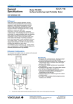
Developed based on years of experience and applications in process fields, the TB750G Right Angle
Scattered Light Turbidimeter provides highly reliable measurement and improved maintainability
which improve upon what previous models could offer. A wide range of options are available to meet
users’ various needs.
The TB750G is a process turbidimeter employing the right angle light scattering method, and has the
following features.
• Highly reliable measurement with excellent linearity and repeatability
- Linearity: ±2% of reading or ±0.01 NTU, whichever is greater
- Repeatability: ±1% of reading or ±0.002 NTU, whichever is greater
- Display resolution: 0.001 NTU
• Easy-to-clean measurement cell
• Compact, lightweight converter and detector
• User configurable analog output range
- Analog output range: 0-0.2 NTU to 0-100 NTU
• Analog output range switching (2 or 3 ranges)
• Enhanced self-diagnostic function as standard
- Light source failure, input element failure, calibration failure, various circuit failures, etc.
• Detector designed to remove influence of air bubbles
• A wide range of measurement conditions
- Low flow rate: 0.05 to 20 l/min
- High pressure: Up to 500 kPa
- Sample temperature: 0 to 50°C
• Detector can be connected for in-line analysis
• 2 analog outputs, 3 relay contact outputs, and 1 serial communication
• Many options available
• Ultrasonic transducer and oscillator for ultrasonic cleaning
• Various head tanks to accommodate application requirements
IM 12E01A06-01E
1-2
<1. OVERVIEW>
1.1
Measurement Principle
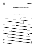
The measuring system of the TB750G turbidimeter, comprised of a detector and a converter, employs
the right angle light scattering method. This section describes the structure of the measuring system
and the measurement principle.
The detector is comprised of a measurement cell, a light source unit, and a sensing unit. A water
sample flows upward through the measurement cell: it flows into the cell from the bottom and flows
out from the top. A tungsten lamp enclosed in the light source unit sends light, through a lens, to the
water in the measurement cell. The incident light passes through the water, and the transmitted light
reaches a receiver, which is located on the opposite side of the light source unit, and is absorbed in
a darkroom equivalent to a black body. The incident light is also scattered by turbidity particles in the
water sample. The intensity of this scattered light, L, is proportional to the turbidity as shown below.
L= K·Q·S
Where:
K: a turbidity-derived constant
Q: the amount of lamp light
S: the turbidity
A turbidity element (a silicon photodiode) in the sensing unit detects light scattered at a right angle to
the incident light beam and sends the output signal to the converter. A reference element incorporated
in the light source unit measures the amount of lamp light, Q, and sends the detection signal to the
converter.
The measuring circuit of the converter is housed, together with an operation panel and a terminal
block for external wiring, in a sealed aluminum alloy enclosure. The circuit amplifies the input voltage
from the sensing unit, calculates, displays the turbidity, and sends the analog output signal (4-20 mA
DC) corresponding to the measuring range and the serial communication data. Either of 4-20 mA DC
or 0-20 mA DC can be selected for analog output 2.
The turbidity reading and output signal are corrected for the change of the amount of lamp light based
on the input from the reference element in the light source unit.
Scatted Light Detection Element
Scatted Light Detector
Receiver (Darkroom)
Light Source Lens
(Lamp)
Measuring
Water
Measurement Window (Glass)
F1-1E.ai
Figure 1.1
IM 12E01A06-01E
Measurement Principle
1.2
1-3
<1. OVERVIEW>
Turbidity Standards
The turbidity standards are used as reference for adjusting a zero or span point of a turbidity meter.
1.2.1 Zero Standard
(1) Zero Turbidity Standard Solution
Filtered tap water is used as a zero turbidity standard solution for the TB750G turbidimeter. For zero
calibration, tap water should be filtered in two steps: first through a 1 µm filter and then through a 0.2
µm filter. If the measuring range exceeds 2.0 NTU, tap water filtered only through a 1 µm filter, can be
used.
Note:The instrument has been pre-calibrated for zero point using tap water filtered through a 0.2
µm filter as a zero turbidity standard solution at the factory before shipment.
(2) Zero Turbidity Filter
The specifications of the zero turbidity filter that can be purchased from Yokogawa is as follows.
Item
Part number
Piping connection
Maximum pressure
Cartridge material
Filter size
Accessory
1 µm Zero Turbidity Filter
K9411UA
Rc1/2
500 kPa
Polypropylene
1 µm
Air vent plug
0.2 µm Zero Turbidity Filter
K9726EF
Rc1/2
500 kPa
Polypropylene
0.2 µm
Air vent plug
1.2.2 Turbidity Standards
(1) Turbidity Standard Solution
A formazin solution is used as a turbidity standard solution for the TB750G turbidimeter.
Note:The instrument has been pre-calibrated for span point using a formazin standard solution at
the factory before shipment.
(2) Check Block
A check block used for span check in regular maintenance, is supplied with the turbidimeter.
Note:The turbidity value indicated on the check block has been determined for the turbidimeter of
interest based on zero and span calibrations at the factory; it is a unique value, specific to the
turbidimeter. Be sure to use the check block supplied with the turbidimeter. Also, special care
should be taken when handling a check block. Scratches or dirt on the surface of a check block
may affect the turbidity value assigned to the block.
NOTE
Using the supplied check block for span calibration is not approved for US EPA applications. For US
EPA applications, perform a 2-point calibration using standard solutions.
IM 12E01A06-01E
1-4
<1. OVERVIEW>
NOTE
Care must be exercised not to lose the check block supplied with the turbidimeter. The check block
has a turbidity value unique to the turbidimeter of interest. Therefore, the same check block cannot be
purchased again. If it is lost, contact Yokogawa.
1.3
Formazin Standard Solution
WARNING
• The reagents are harmful if inhaled or swallowed.
• In case of contact with skin, flush skin with plenty of soap and water. Seek medical advice, as
appropriate, if symptoms appear.
• A Class A extinguisher should be provided in work area.
• Wear protective goggles, lab coat, and protective gloves to prevent skin contact. Use a vent
hood in the indoor workplace.
• For details of the chemical handling, refer to the Material Safety Data Sheets (MSDS).
A turbidity standard calibration solution should be prepared by diluting a 400 NTU formazin standard
stock solution. This section describes the procedures for preparing a standard stock solution and a
diluted solution for calibration.
1.3.1 Preparing a Formazin Standard Stock Solution
(1) Reagents Required
• Hydrazine sulfate, (NH2)2·H2SO4
• Hexamethylene tetramine, (CH2)6·N4
(2) Equipment Required
• Measuring flask, 2 x 100 ml
• Measuring flask, 1000 ml
• Volumetric pipette, 50 ml
• Analytical balance
Note:Class A volumetric flasks and pipets are required.
(3) Procedure
1. Weigh out 1.000 g ±0.001 g of hydrazine sulfate with a balance, place it in a 100-ml measuring
flask, and add deionized water to make 100 ml (solution A).
2. Weigh out 10.00 g ±0.01 g of hexamethylene tetramine with a balance, place it in another 100-ml
measuring flask, and add deionized water to make 100 ml (solution B).
3. Make sure that both reagents have been completely dissolved in solutions A and B, respectively.
Pipette 50 ml each of solutions A and B into a 1000-ml measuring flask and mix well.
4. Allow the mixed solution to stand for 24 hours at 25 ±3°C.
IM 12E01A06-01E
1-5
<1. OVERVIEW>
5. Bring the total volume to 1000 ml with deionized water.
This is a 400 NTU formazin standard stock solution and its storage life is one month. To make a
standard solution of the desired turbidity, dilute this stock solution with deionized water.
1.3.2 Preparing a Formazin Calibration Standard Solution
To make a formazin calibration standard solution, dilute the 400 NTU formazin standard stock
solution.
(1) Precautions
• Use clean, high quality laboratory glassware and measure the volume needed accurately.
• To dilute the formazin standard stock solution, use deionized water or water filtered through a 0.2
µm zero turbidity filter.
• Before dilution, mix the stock solution thoroughly.
(2) Procedure
To make a 2000 ml formazin calibration standard solution of the desired turbidity, take the needed
volume of the 400 NTU formazin standard stock solution and dilute to 2000 ml.
Turbidity
20 NTU
10 NTU
5 NTU
2 NTU
1 NTU
Aliquot of Stock Solution
100 ml
50 ml
25 ml
10 ml
5 ml
Total Volume
2000 ml
2000 ml
2000 ml
2000 ml
2000 ml
IM 12E01A06-01E
1-6
IM 12E01A06-01E
<1. OVERVIEW>
<2. SPECIFICATIONS>
2-1
2.SPECIFICATIONS
2.1
Standard Specifications
TB750G Right Angle Scattered Light Turbidimeter
Measurement: Turbidity of finished water and water used in general processes
Measurement method: Right angle light scattering method
Measuring range:0.000 to 100.0 NTU
Display: 4 digit LCD (6 digits in message area), negative value indication enabled/disabled
Unit:
NTU
Resolution: 0.001 NTU
Turbidity standard: Formazin
Analog output:
Number of outputs: 2
Output signal:
Analog output 1: 4 to 20 mA DC, isolated
Analog output 2:4 to 20 mA DC or 0 to 20 mA DC selectable,
isolated (Both analog outputs are not isolated.)
Load resistance:
550Ω max.
Output range:Configurable within the measuring range
Minimum range: 0 to 0.2 NTU
Maximum range: 0 to 100 NTU
Minimum span: 20% or more of upper limit of the range or 0.2 NTU, whichever is greater.
Note: When auto range switching is selected, lower limit of the range is 0 NTU.
Range switching: Enabled/disabled in either analog output 1 or 2. Not available in both outputs.
Manual (local) range/auto range/remote 2-range/remote 3-range switching
selectable.
Output signal in maintenance:Output hold enabled/disabled
Hold output:Last measured value or fixed value (between 2.0 and 22.0 mA for 4 to 20 mA DC
output; between 0.0 and 22.0 mA for 0 to 20 mA DC output) selectable
Output signal in FAIL: Output hold enabled/disabled
Hold output:Last measured value or fixed value (between 2.0 and 22.0 mA for 4 to 20 mA DC
output; between 0.0 and 22.0 mA for 0 to 20 mA DC output) selectable
Negative value indication: Enabled/disabled
Serial communication:
Number of outputs: 1
Communication signal: RS-422 or RS-232C, isolated
Communication specifications:
Data format: ASCII
Transmission speed: 9600 bps
Parity bit:
Even parity
Stop bit:
1
Data length: 8 bits
Transmission method:
Asynchronous, non-procedural
Communication description:
IM 12E01A06-01E
2-2
<2. SPECIFICATIONS>
(1) Turbidity
Request command (receive data):
C R 0 C 5 CR LF
SUM: The last two digits of the total before SUM
Turbidity read command
Communication data (transmit data):
A R 0 CR LF
SUM
Turbidity
Turbidimeter status information
Communication status
Turbidity read return status
Communication status: See Note in case other than 0
0 (no communication error), 1 (parity error), 2 (framing error),
3 (overrun error), 4 (check sum error), 5 (command error)
Turbidimeter status information:
Operation status: 0 (in measurement), 1 (in calibration), 2 (in maintenance excluding calibration)
Range status (output range 2): 0 (fixed range), 1 (range A), 2 (range B), 3 (range C)
Range status (output range 1): 0 (fixed range), 1 (range A), 2 (range B), 3 (range C)
Alarm generation: 0 (no alarm), 1 (alarm generated)
Error generation: 0 (no error), 1 (error generated)
Turbidity (the same significant digits as turbidimeter reading):
Unit: 1 (NTU), 2 (FNU), 3 (mg/l)
Number: Right aligned, including decimal point, no number denoted by blank
+/- (negative) sign: + denoted by blank
SUM: The last two digits of the total before SUM
Note:Return data when a communication error occurs
A R 0 CR LF
SUM
Communication status: (except 0)
Example 1: When the turbidity is 3.89,
Request command (receive data):CR0C5CRLF
Return data (transmit data):AR0000100_ _3.89127CRLF
(A space code is transmitted by “_”)
(2) Error information (excluding E351 and E352)
Error information request command (receive data):
C R 2 C 7 CR LF
SUM: The last two digits of the total before SUM
Error information read command
Return data (transmit data):
A R 2 CR LF
SUM
Error information 5 (hexadecimal)
Error information 4 (hexadecimal)
Error information 3 (hexadecimal)
Error information 2 (hexadecimal)
Error information 1 (hexadecimal)
Turbidimeter status information
Communication status
Error information return status
Communication status: See Note in case other than 0
0 (no communication error), 1 (parity error), 2 (framing error),
3 (overrun error), 4 (check sum error), 5 (command error)
IM 12E01A06-01E
2-3
<2. SPECIFICATIONS>
Turbidimeter status information:
Operation status: 0 (in measurement), 1 (in calibration), 2 (in maintenance excluding calibration)
Range status (output range 2): 0 (fixed range), 1 (range A), 2 (range B), 3 (range C)
Range status (output range 1): 0 (fixed range), 1 (range A), 2 (range B), 3 (range C)
Alarm generation: 0 (no alarm), 1 (alarm generated)
Error generation: 0 (no error), 1 (error generated)
Error information 1 (hexadecimal):
Error code:
E101 to E104
Bit configuration:
0 (no error), 1 (error generated)
15 14 13 12 11 10 9 8 7 6 5 4 3 2 1 0
E101
E102
E103
E104
Reserved (0)
Error information 2 (hexadecimal):
Error code:
E201 to E205
Bit configuration:
0 (no error), 1 (error generated)
15 14 13 12 11 10 9 8 7 6 5 4 3 2 1 0
E201
E202
E203
E204
E205
Reserved (0)
Error information 3 (hexadecimal):
Error code:
E301 to E307
Bit configuration:
0 (no error), 1 (error generated)
15 14 13 12 11 10 9 8 7 6 5 4 3 2 1 0
E301
E302
E303
E304
E305
E306
E307
Reserved (0)
Error information 4 (hexadecimal):
Reserved
Bit configuration
15 14 13 12 11 10 9 8 7 6 5 4 3 2 1 0
Reserved (0)
Error information 5 (hexadecimal):
Error code:
E321, E322
Bit configuration:
0 (no error), 1 (error generated)
15 14 13 12 11 10 9 8 7 6 5 4 3 2 1 0
E321
E322
Reserved (0)
SUM: The last two digits of the total before SUM
IM 12E01A06-01E
2-4
<2. SPECIFICATIONS>
Note:Return data when a communication error occurs
A R 2 CR LF
SUM
Communication status: (except 0)
Example 2: When E205 and E301 errors are occurring,
Request command (receive data):CR2C7CRLF
Return data (transmit data): AR201010200000010000100000000ABCRLF
(3) Output range switching
Output switching request command (receive data):
C W 0 C 5 CR LF
SUM: The last two digits of the total before SUM
Switching range selection: 0 (range A), 1 (range B), 2 (range C)
Analog output selection: 0 (analog output 1), 1 (analog output 2)
Output range switching command
Return data (transmit data):
A W 0 CR LF
SUM
Turbidimeter status information
Communication status
Range switching request return status
Communication status: See Note in case other than 0
0 (no communication error), 1 (parity error), 2 (framing error),
3 (overrun error), 4 (check sum error), 5 (command error)
Turbidimeter status information:
Operation status: 0 (in measurement), 1 (in calibration), 2 (in maintenance excluding calibration)
Range status (output range 2): 0 (fixed range), 1 (range A), 2 (range B), 3 (range C)
Range status (output range 1): 0 (fixed range), 1 (range A), 2 (range B), 3 (range C)
Alarm generation: 0 (no alarm), 1 (alarm generated)
Error generation: 0 (no error), 1 (error generated)
SUM: The last two digits of the total before SUM
Note:Return data when a communication error occurs
A W 0 CR LF
SUM
Communication status: (except 0)
Example 3: When output range 1 is switched to range A,
Request command (receive data):
CW0002ACRLF
Return data (transmit data): AW00001000EBCRLF
Transmission distance:RS-422: 1000 m max.
RS-232C: 10 m max.
Cable:
RS-422: Twisted pair cable with shield (AWG 20 to 16)
RS-232C: Cable with shield
Contact output:
Type:
Relay contact output
Number of contacts: 3
Action:
On/Off
Function:
S1, S2:
High/low alarm or in-maintenance selectable
FAIL:
Failure
Rating:250 VAC, 2A, 125 VA max. (resistance load) or 30 VDC, 3A, 60 W max. (resistance
load), Form C (NC/NO/COM, 3 terminals)
IM 12E01A06-01E
2-5
<2. SPECIFICATIONS>
Contact status:
Status
In action
Not in action
Power OFF
Contact S1, S2
LED
NO
NC
ON
Closed Open
OFF
Open Closed
OFF
Open Closed
LED
ON
OFF
OFF
Contact FAIL
NO
NC
Open Closed
Closed Open
Open Closed
Contact input:
Type:
Voltage-free contact input
Number of contacts: 2
Function:
Remote range switching
On resistance: Input resistance 200Ω or less
Off resistance: Input resistance 100 kΩ or greater
Contact status:
Remote 2-range switching
Contact
IN1-COM
When Range Switching is Selected
Range A
Range B
Open
Closed
Remote 3-range switching
Contact
IN1-COM
IN2-COM
Range A
Open
Open
When Range Switching is Selected
Range B
Range C
Closed
Open
Open
Closed
Range contact output:
Type:
Relay contact output
Number of contacts: 3
Action:
On/Off
Rating:250 V AC, 2 A, 125 VA max. (resistance load) or 30 V DC, 3 A, 60 W max. (resistance
load)
Contact status:
Contact
RANGE A-COM
RANGE B-COM
RANGE C-COM
When Fixed Range
is Selected
Open
Open
Open
When Range Switching is Selected
Range A
Range B
Range C
Closed
Open
Open
Open
Closed
Open
Open
Open
Closed
Calibration:
Zero calibration: Zero water (filtered water with zero turbidity)
Span calibration:Sensitivity calibration using check block or turbidity standard solutions
2-point calibration: Turbidity standard solutions
Grab sample calibration: Zero point and sensitivity correction using grab sample
Self-diagnostics:Light source failure, input element failure, calibration failure, AD circuit failure,
memory failure, etc.
Installation location: Indoor (Weather protection is required for outdoor installation)
Ambient temperature: -5 to 50°C (Sample and tap water may need protection against freezing)
Ambient humidity: 5 to 95%RH (non-condensing)
Storage temperature: -30 to 70°C
Sample water conditions:
Flow rate:
0.05 to 20 l/min
Temperature: 0 to 50°C
Pressure:
500 kPa max.
Mounting:
Pipe, wall, rack or panel mounting
Piping connection (detector):
Sample water inlet: Rc1/2 or 1/2NPT (optional)
IM 12E01A06-01E
2-6
<2. SPECIFICATIONS>
Sample water outlet:Rc1/2 or 1/2NPT (optional)
Drain port:
Rc1 or 1NPT (optional)
Cable inlet port (detector and converter):
DIN Pg 13.5 cable gland
Cable OD.:6 to 12 mm
Dimensions:
Detector: 378W x 174H x 265D mm
Converter:144W x 144H x 142D mm
Material (main):
Detector:
Aluminum alloy casting, modified PPE resin
Wetted parts: Modified PPE resin, glass, fluoric rubber, silicon rubber, SUS316
Converter: Aluminum alloy casting, Polycarbonate resin
Construction: JIS C 0920, IP65 Water-tight
Finish:
Detector, Converter:
Baked polyurethane resin coating (standard)
Baked epoxy resin coating (optional)
Color:
Detector:Spring Black (Munsell 3.3PB2.5/0.5 or equivalent), Mint green (Munsell
5.6BG3.3/2.9 or equivalent)
Converter: Silver Gray (Munsell 3.2PB7.4/1.2 or equivalent)
Weight:
Detector:
Approx. 5.8 kg
Converter: Approx. 1.5 kg
Power supply: 100 to 240 VAC -15%/+10%, 50/60 Hz
Grounding:Class D grounding
Grounding resistance of 100Ω or less
Power consumption: Converter + Detector: 50 VA max.
EMC Regulatory Arrangement in Australia and New Zealand:
EN55011 Class A, Group 1
KC Marking: Korea Electromagnetic Conformity Standard
A급 기기 (업무용 방송통신기자재)
이 기기는 업무용(A급) 전자파적합기기로서 판매자 또는
사용자는 이 점을 주의하시기 바라며, 가정외의 지역에서
사용하는 것을 목적으로 합니다.
2.2Characteristics
Standard performance (under normal operating conditions)
Repeatability:±1% of reading or ±0.002 NTU, whichever is greater
Linearity:
±2% of reading or ±0.01 NTU, whichever is greater
Response time: Within 2 minutes (90% response, sample water flow rate 3 l/min)
2.3
Optional Specifications
Head tank:
Simple head tank
Application: Turbidity is 10 NTU or less. To remove relatively large air bubbles.
Sample water conditions:
Flow rate:
1 to 10 l/min
Turbidity:
2 to 10 NTU
Pressurized head tank for low turbidity
Application: Turbidity is 2 NTU or less. To remove air bubbles and to prevent them from occurring.
Sample water conditions:
Flow rate:
0.05 to 10 l/min
Turbidity:
2 NTU or less
Pressure:
20 to 500 kPa
IM 12E01A06-01E
<2. SPECIFICATIONS>
2-7
Transducer for ultrasonic cleaning
(TUS400G Ultrasonic Oscillator should be purchased separately.)
Zero turbidity filter
When measuring range is 2.0 NTU or greater:
1 µm
When measuring range is below 2.0 NTU:
1 µm + 0.2 µm
2.4
Model and Codes
2.4.1 TB750G Right Angle Scattered Light Turbidimeter
Model
TB750G
Turbidity
standard
and
measuring
range
Application
Output
Option
Description
code
- - - - - - - - - - - - - - - - - - - - - - - - - - - - - - - - - - - - - - - - - - Right angle scattered light turbidimeter
–NTU
- - - - - - - - - - Formazin, 0-0.2 NTU to 0-100 NTU
Suffix code
–ST
–N1
–N2
Sampling system
–NN
Sampling system material and
NN
mounting
Cable length between converter and
–1
detector
–2
–3
–
–NN
Option
Detector process connection
Mounting hardware
Conduit adapter
Head tank
Tag plate
Special painting
Ultrasonic transducer
----------------------------------------------
Standard
4 to 20 mA DC, RS-422
4 to 20 mA DC, RS-232C
Without sampling system
Without sampling system
------------------------------------/NPT
/U
/R
/PM
/TBC
/AFTG
/ANSI
/D1
1m
2m
3m
Always –NN
ANSI standard connection *1
Pipe mounting hardware (SUS)
Rack or wall mounting hardware (SUS)
Panel mounting hardware (SUS)
Mounting hardware for Model 8562 or Model TB500G
replacement (SUS) *2
G1/2 *3
1/2NPT *3
Pressurized head tank for low turbidity /D2
/SCT
/X1
Simple head tank
Stainless steel tag plate
Epoxy painting *4
/US
(recommended for 2.0 NTU or less)
Transducer for ultrasonic cleaning *5
*1: When option "/NPT" is specified, the piping connections of sample water inlet, sample water outlet, and drain port
are 1/2NPT, 1/2NPT, and 1NPT respectively. Unless option "/NPT" is specified, they are Rc1/2, Rc1/2, and Rc1
respectively.
*2: This bracket is also available to the detector of Turbidimeter 1720E and 1720D manufactured by HACH.
It is separete type, each for detector and converter.
*3: Conduit adapter is for power supply, output and input wiring provided by customer.
*4: Converter and detector case are painted with epoxy resin.
*5: Specify option "/US" (ultrasonic transducer) for ultrasonic cleaning. Also TUS400G Ultrasonic Oscillator should
be purchased separately.
Note:When ultrasonic cleaning is continuously used after the Model 8562 Turbidity Transmitter has been
replaced with the TB750G Turbidimeter, this "/US" option must be specified.
2.4.2 Zero Turbidity Filter Assembly
Part Name
Filter Assembly, 1µm
Filter Assembly, 0.2µm
Part No.
K9411UA
K9726EF
IM 12E01A06-01E
2-8
<2. SPECIFICATIONS>
2.4.3Accessories
Item
Lamp assembly
Fuse, 3.15 A
Desiccant
Silicon cloth
Check block
Qty
1
2
1
1
1
Description
3.15A
4 pcs, Part Number: K9657RJ
Part Number: K9210KS
2.4.4Consumables
Part Name
Filter Element, 1 µm
Filter Element, 0.2 µm
Lamp Assembly (for TB750G)
Fuse (3.15 A)
Desiccant (4 pcs) *1
Part No.
K9008ZD
K9726EH
K9657PW
A1113EF
K9657RJ
*1: Use within a year after purchasing.
2.4.5 Head Tank
Part Name
Pressurized head tank
Simple head tank
IM 12E01A06-01E
Part No.
K9725WA
K9658YA
Description
Same as option code /D1
Same as option code /D2
2-9
<2. SPECIFICATIONS>
2.5
External Dimensions
2.5.1 TB750G Right Angle Scattered Light Turbidimeter
Converter
Unit: mm
141.5
132
4-M6 screws
(144)
150 min.
80
144
150 min.
(141.5)
144
50
min.
(30)
Maintenance space
to Detector
Detector connecting
cable inlet
6- Cable inlets
DIN Pg13.5
Cable gland
80
Grounding terminal
(M4 screw)
Dedicated cable (1/2/3m)
F2-1E.ai
Detector
Unit: mm
Side view
250 min.
250 min.
200 min.
(378)
378
(265.3)
(297)
265
500 min.
500 min.
Front view
(265)
Maintenance space
60
38
Power cable inlet *
Ultrasonic oscillator (for power)
connecting cable inlet *
("/US" only)
Converter connecting
cable inlet *
20
Sample water
Dedicated cable inlet
Rc1/2 or 1/2NPT
(1/2/3m)
from
Converter
Ultrasonic transducer
connecting cable inlet *
("/US" only)
* Cable gland DIN Pg13.5
63
41
180
20
174
Sample water outlet
Rc1/2 or 1/2NPT
113
56
Drain
Rc1 or 1NPT
F2-2E.ai
IM 12E01A06-01E
2-10
<2. SPECIFICATIONS>
• Conduit adapter (option code: /AFTG, /ANSI)
Nut
Unit: mm
Case
49
Cable gland
Approx. 55
Packing
Adapter
G1/2(/AFTG) or
1/2NPT(/ANSI)
F2-3E.ai
For external dimensions of mounting hardware (option code: /U, /R, /TBC) and head tank (option
code: /D1, /D2), refer to Chapter 3.
2.5.2 Zero Turbidity Filter Assembly
OUT
Unit: mm
44
112.5
4-M4
fixing screws
IN
80
ø115
ø121
Piping inlet & outlet
Rc1/2
314
22 22
Vent plug
Filter element
10
Part No.
K9411UA
K9726EF
IM 12E01A06-01E
Filtering size
1 µm
0.2 µm
F2-4E.ai
2.6
<2. SPECIFICATIONS>
2-11
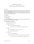
Piping Diagram
The Piping diagram recommended is shown below. Refer to Section 3.3 for details.
Head Tank
H
Flow Control Valve
Sample Water
Effluent
Sample Water Drain
Valve
Valve
Drain
Tap
Water
TB750G
Detector
Drain
Sample Water Sample Water
Inlet
Sample Water
Supply Valve
Zero Water
h
Sample Water
Outlet
Sample
Water
Drain
Drain Port
Drain Valve
Drain
Zero Water Supply Valve
Tap Water
Valve
Zero Water
Drain Valve
Other Turbidity Detectors
Zero Turbidity
Filter
F2-5E.ai
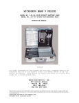
2.7
Connection Diagram
TB750G Turbidity detector
TB750G Turbidity converter
L
CONVERTN POWER
ER
G
G
Power
supply *5
Grounding *1
(100Ω or less)
L
N TUS
G
Dedicated cable (1/2/3m)
U1U2
Grounding *1
(100Ω or less)
Power supply
cable*6
Serial communication *3 *4
(RS-422)
Ultrasonic transducer
connecting cable
(maximum length: 15m)
(customer wiring)
Contact input
TUS400G Ultrasonic Oscillator *5
L2
L1
SENSOR
S1
NO
NC
COM
Contact
output S1
S2
NO
NC
COM
Contact
output S2
FAIL
NO
NC
COM
Contact
output FAIL
RANGE
A
B
C
COM
Range
contact output
G
U1
U2
U3
S
Analog output 1
(4-20mA DC) *3
Analog output 2
(4-20mA DC or
0-20mA DC) *3
Grounding *2
(100Ω or less)
RX+
RXTX+
TXSG
G
IN1
IN2
COM
+
+
G
RS-422
INPUT
mA1
mA2
OUTPUT
Grounding *1
(100Ω or less)
(Note)Dotted wiring is external wiring. Use cable with 6 to 12 mm OD for wiring.
*1 Power terminal "G" on detector, detector case, and converter case must be grounded (ground resistance: 100Ω or less).
*2 External grounding terminal of ultrasonic oscillator must be grounded (ground resistance: 100Ω or less).
*3 Use 2-conductor shielded cable for analog output wiring and serial communication wiring.
*4 The wiring configuration is described below in case that RS-232C serial communication is selected.
Serial communication
(RS-232C)
*5
*6
TXD
RXD
SG
G
RS-232C
When option code "/US" isspecified, TUS400G should be purchased separately.
When TUS400G is used in system, the power supply to TB750G should be the same as the supply voltage specified in
the MS Code of TUS400G.
When "TB750G/US" and "TUS400G-NN-RC" or "TUS400G-NN-KC" is specified, refer to IM 19C1B4-01E for wiring.
F2-6E.ai
IM 12E01A06-01E
Blank Page
3.
3-1
<3. INSTALLATION, PIPING, AND WIRING>
INSTALLATION, PIPING, AND WIRING
3.1Installation
3.1.1 Unpacking
The TB750G turbidimeter has been carefully packed and then shipped to prevent damage during
transportation. Upon receipt of the instrument, unpack with care.
3.1.2 Installation Location
The TB750G turbidimeter should be installed in a location:
• that is protected from direct sunlight and rain, i.e., the instrument should be installed indoors or in
a cubicle;
• that is subject to minimal mechanical vibration;
• where no corrosive gases are present;
• that is not exposed to high temperature and humidity. The temperature should be in the range of
-5 to 50°C, preferably at or around normal temperatures, and its fluctuation small. The humidity
should be kept between 10 to 90%RH. Prevent condensation which may occur if the sample
temperature is lower than the ambient temperature. Also, take protective measures to prevent a
sample water and the tap water from freezing, if necessary;
• that provides adequate maintenance space and easy access for maintenance work;
• where the drain is provided; and,
• where the converter can be installed in the vicinity of the detector.
IM 12E01A06-01E
3-2
<3. INSTALLATION, PIPING, AND WIRING>
3.1.3 Installation Dimensions
Install the TB750G’s converter and detector in pipes, racks or walls using their special mounting
brackets, respectively. Note that these mounting brackets are supplied only when specified.
n Pipe Mounting (Option Code “/U”)
Converter
Unit: mm
195
132
Mounting pipe
Nominal 50A (ø60.5 OD)
224
144
144
100
(Note) Dedicated cable is omitted.
F3-1E.ai
Detector
Unit: mm
84
113
102
48
Sample water
outlet
Rc1/2 or 1/2NPT
25
47
180
202
12
20
Mounting pipe
Nominal 50A
(ø60.5 OD)
20
Sample water inlet
Rc1/2 or 1/2NPT
(Note) Dedicated cable is omitted.
IM 12E01A06-01E
Drain
Rc1 or 1NPT
F3-2E.ai
3-3
<3. INSTALLATION, PIPING, AND WIRING>
n Rack/Wall Mounting (Option Code “/R”)
Converter
Unit: mm
154.5
144
70
224
144
132
70
4-ø10
70
(Note) Dedicated cable is omitted.
F3-3E.ai
Detector
63
41
R3
180
174
7
R3
160 (for fixing hole)
2-ø6 (fixing holes)
Unit: mm
38
60
Sample water
outlet
Rc1/2 or 1/2NPT
20
6
6
20
100 (for fixing hole)
Sample water inlet
Rc1/2 or 1/2NPT
(Note) Dedicated cable is omitted.
113
56
Drain
Rc1 or 1NPT
F3-4E.ai
IM 12E01A06-01E
3-4
<3. INSTALLATION, PIPING, AND WIRING>
n Panel Mounting (Option Code “/PM”)
Converter
15 max.(panel thickness)
Unit: mm
4-M6 screws
138 +2
0
195 min.
100
138 0
+2
27
178
185 min.
<Panel cutout>
(Note) Dedicated cable is omitted.
F3-5E.ai
Detector
63
41
R3
180
174
7
R3
160 (for fixing hole)
2-ø6 (fixing holes)
Unit: mm
38
60
Sample water
outlet
Rc1/2 or 1/2NPT
20
6
6
20
100 (for fixing hole)
Sample water inlet
Rc1/2 or 1/2NPT
(Note) Dedicated cable is omitted.
IM 12E01A06-01E
113
56
Drain
Rc1 or 1NPT
F3-6E.ai
3-5
<3. INSTALLATION, PIPING, AND WIRING>
n Replacing Model 8562 or TB500G Detector (Option Code “/TBC”)
Converter
Unit: mm
154.5
144
70
224
144
132
70
4-ø10
70
(Note) Dedicated cable is omitted.
F3-7E.ai
Detector
273 (for fixing hole)
100 (for detector fixing screw)
4-M5
(fixing screws of detector)
38
25
139
7
63
41
160
(for detector fixing screw)
(20)
77
6
31
112 (for fixing hole)
R3
6
Sample water
outlet
Rc1/2 or 1/2NPT
R3
20
Unit: mm
20
70 (for fixing hole)
174
4-ø9
(for fixing hole)
Sample water
inlet
Rc1/2 or 1/2NPT
(Note) Dedicated cable is omitted.
113
56
Drain
Rc1 or 1NPT
F3-8E.ai
IM 12E01A06-01E
3-6
<3. INSTALLATION, PIPING, AND WIRING>
3.1.4Preparation
Attaching Optional Parts
Optional parts, such as mounting brackets or conduit adapters, are supplied with the instrument when
specified. To avoid misplacing any of these parts, it is recommended that they should be attached to
the instrument before installation.
Preparing an Installation Site
Prepare an installation site for the TB750G so that easy operation and maintenance are allowed.
(1) Pipe Mounting
The TB750G is fixed to a stanchion (pipe) with a U-bolt. Construct a rigid pipe with an outside
diameter of 60.5 mm vertically (or horizontally for converter).
(2) Wall Mounting
The TB750G converter is mounted on the wall with three M8 bolts (supplied by customer). Drill the
holes in the wall as shown in Figure 3.1.
144
Unit: mm
TB750G Converter
144
102
35
70
Figure 3.1
F3-9E.ai
Drilling for Wall Mounting Converter
The TB750G detector is mounted on the wall with four M5 bolts (supplied by customer). Drill the holes
in the wall as shown in Figure 3.2.
(93)
Figure 3.2
IM 12E01A06-01E
Unit: mm
(20)
160
TB750G
Detector
(57)
(180)
(60)
(378)
100
Drilling for Wall Mounting Detector
F3-10E.ai
<3. INSTALLATION, PIPING, AND WIRING>
3-7
(3) Panel Mounting
In the mounting position of the TB750G converter, make a panel cutout as shown in Figure 3.3. The
thickness of a panel should not exceed 15 mm.
+2
138 0
195 min.
138 0
+2
Unit: mm
185 min.
F3-11E.ai
Figure 3.3
Cutout for Converter’s Panel Mounting
As with (2) Wall Mounting, the TB750G detector is mounted on a panel with four M5 bolts (supplied by
customer). Drill the holes in the panel as shown in Figure 3.2.
IM 12E01A06-01E
3-8
<3. INSTALLATION, PIPING, AND WIRING>
3.1.5 Mounting the Converter and Detector
(1) Pipe Mounting
Figures 3.4 and 3.5 show the pipe mounting brackets and the mounting procedures.
Bracket Retaining Screws
Converter
Bracket
Pipe Bracket
U-bolt
Nuts (2)
Washers (2)
Stanchion (pipe 50A)
F3-12E.ai
Figure 3.4
Pipe Mounting, Converter
Stanchion
(pipe 50A)
Detector
U-bolt (2)
Nuts (4)
Pipe Bracket (2)
F3-13E.ai
Figure 3.5
IM 12E01A06-01E
Pipe Mounting, Detector
<3. INSTALLATION, PIPING, AND WIRING>
3-9
(2) Wall Mounting
Figures 3.6 and 3.7 show the wall mounting procedures.
Converter
Mounting Holes (3)
M8 Bolts (3, supplied by customer)
Should be long enough to be
secured through mounting hole.
Bracket
F3-14E.ai
Figure 3.6
Wall Mounting, Converter
Wall
Detector
M5 Bolts (4, supplied by customer)
Should be long enough to be
secured through mounting hole. Mounting Holes (4)
F3-15E.ai
Figure 3.7
Wall Mounting, Detector
(3) Panel Mounting
Figure 3.8 shows the panel mounting procedure for the converter.
Panel
Converter
Bracket
Mount the converter
by inserting it into the
panel cut opening.
Setscrews (2)
Figure 3.8
F3-16E.ai
Panel Mounting, Converter
The procedure for detector’s panel mounting is the same as the one for its wall mounting. See Figure
3.7.
IM 12E01A06-01E
3-10
<3. INSTALLATION, PIPING, AND WIRING>
Depending on the installation position, the converter-detector connecting cable may need to be
disconnected once. In that case, disconnect the cable end from the converter by following the
instructions below.
< How to Disconnect the Converter-Detector Connecting Cable >
(a) Connector
1. Open the front cover of the converter.
Next, remove the following.
(a) Connector
(b) Grounding wire
(c) Ferrite core
(c) Ferrite Core
(b) Grounding Wire
2. Loosen the cable gland and pull out the cable
gland's ring that is attached to the inside of the
cable inlet port on the converter.
Cable Gland's Ring
3. Slide the ring over the cable, the connector and
the wire until it comes off. Orient the connector as
shown in the picture to the left so that it goes
through the ring.
4. Remove the cable and the wire from the converter
by carefully pulling them out through the port.
To reconnect the cable to the converter, reverse
the above steps.
Note: Remove all cable glands before inserting the
converter into the panel cut opening.
F3-17E.ai
IM 12E01A06-01E
3-11
<3. INSTALLATION, PIPING, AND WIRING>
3.2Wiring
3.2.1 Wiring Required for the TB750G
Wiring for the Converter
(1) Analog output wiring
(2) Contact input (remote range switching) wiring
(3) Range contact output wiring
(4) Contact output (S1, S2 and FAIL) wiring
(5) Serial communication wiring
(6) Checking wiring to the detector
(7) External ground wiring
Wiring for the Detector
(8) Power and ground wiring
(9) External ground wiring
(10) Power wiring for ultrasonic oscillator (when option code “/US” is specified)
(11) Wiring to ultrasonic transducer (when option code “/US” is specified)
CAUTION
Before opening the front cover of the converter or the detector, turn off power to the TB750G
turbidimeter. Make sure that the turbidimeter is not powered before wiring work. Do not touch
terminals while the turbidimeter is being powered.
NOTE
The TB750G turbidimeter does not have an internal power switch. Be sure to provide a switch (double
pole type, compliant with IEC 60947-1 and IEC 60947-3) in the power line as close to the instrument
as possible. The “|” (on) and “O” (off) symbols should be indicated near the switch if they are not
indicated on the switch.
Converter - Detector
Connecting Cable
Front Cover
Serial Communication
Terminals
Connector for
Converter - Detector Cable
Serial Communication
Front Cover
Terminals
Terminal Cover
Terminal G
(For Converter Detector Connecting Cable)
Analog Output/Contact Input Terminals
Figure 3.9
Contact Output/
Range Contact
Output Terminals
Analog Output/Contact Input Terminals
F3-18E.ai
Internal View of the Converter
IM 12E01A06-01E
3-12
<3. INSTALLATION, PIPING, AND WIRING>
Terminals TM3 (Power to Lamp)
Power Supply Terminals
Power Supply Terminals for
Ultrasonic Oscillator
Figure 3.10
Terminal G
(For Converter - Detector
Connecting Cable)
Connector for Converter - Detector Cable
F3-19E.ai
Internal View of the Detector
[Procedure for Wiring]
Procedure for Wiring to the Converter
Before wiring work, make sure that the power supply is disconnected from the TB750G converter.
Remove the front cover by loosening the 4 setscrews holding the cover to the converter. Remove the
terminal cover and also remove the grounding terminals of both the converter and the detector. Then,
make the following wiring connections.
(1) Analog output wiring
(2) Contact input (remote range switching) wiring
(3) Range contact output wiring
(4) Contact output (S1, S2 and FAIL) wiring
Attach the terminal cover and also replace the grounding terminals of both the converter and the
detector. Then, make the following wiring connection.
(5) Serial communication wiring
(6) Checking wiring to the detector
(7) External ground wiring
Close the converter’s front cover and tighten the 4 setscrews to fix the cover.
Procedure for Wiring to the Detector
Before wiring work, make sure that the power supply is disconnected from the TB750G turbidimeter.
Remove the front cover by loosening the 4 setscrews holding the cover to the detector.
(8) Power and ground wiring
(9) External ground wiring
(10) Power wiring for ultrasonic oscillator (when option code “/US” is specified)
Replace the front cover and tighten the 4 setscrews. Then, remove the left side cover on the detector
by loosening the 4 setscrews holding the cover to the detector.
(11) Wiring to ultrasonic transducer (when option code “/US” is specified)
Replace the side cover and tighten the 4 setscrews.
IM 12E01A06-01E
<3. INSTALLATION, PIPING, AND WIRING>
3-13
3.2.2 Cable Inlet Port
The TB750G converter has 6 cable inlet ports and the detector has 3 cable inlet ports. A cable gland
corresponding to the cable with an outside diameter of 6 to 12 mm, is attached to each cable inlet port.
Run each cable through the specified ports as shown in Figures 3.11 and 3.12. Unused cable inlet
ports, if any, should be plugged to prevent dust or foreign matter from entering.
A
B
C
D
E
F
A: For Converter - Detector Cable
B: For Contact Output (S1, S2, FAIL)
C: For Serial Communication
D: For Contact Input
E: For Analog Output
F: For Range Switching Contact Output
External Grounding Terminal (M4 Screw)
Figure 3.11
Cable Inlet Ports of the Converter
H
G
F3-20E.ai
K
G: For Power Supply
H: For Power Cable to Ultrasonic Oscillator
J: For Cable to Ultrasonic Transducer
K: For Converter - Detector Cable
J
F3-21E.ai
Figure 3.12
Cable Inlet Ports of the Detector
When conduits are used to protect cables, use adapters: six pieces are supplied when option code
“/AFTG” is specified). Remove cable glands from cable inlet ports B, C, D, E, and F, and attach
adapters and cable glands as shown in Figure 3.13.
No conduit work is done with cable inlet port A, a port for a cable connecting the converter and the
detector. Use the cable glands originally attached to the port.
Case
Packing
49
Cable Gland
Unit: mm
Approx.55
Nut
Adapter
G1/2(/AFTG) or
1/2NPT(/ANSI)
Figure 3.13
F3-22E.ai
Conduit Adapter
IM 12E01A06-01E
3-14
<3. INSTALLATION, PIPING, AND WIRING>
3.2.3 Analog Output Wiring
This wiring is for transmitting an output signal of the converter to a receiver such as a recorder. Two
outputs are available: output 1 (4-20 mA DC) and output 2 (4-20 or 0-20 mA DC).
CAUTION
Before opening the front cover of the converter or the detector, turn off power to the TB750G
turbidimeter. Make sure that the turbidimeter is not powered before wiring work. Do not touch
terminals while the turbidimeter is being powered.
[Cable Required]
Use a shielded cable with a finished outside diameter of 6 to 12 mm. The number of conductors is
determined by that of signals: 2 or 4 conductors.
[Procedure]
(1)Terminating the cable.
Strip off approximately 40 mm of the insulation from the end of the cable. Cut off the exposed
shield as short as possible and solder a lead wire for grounding (with approximately the same
length as the conductor) to the remaining exposed shield. Wrap the soldered area with an
insulating tape or relevant protection.
Then, terminate the ends of the lead wire and the conductors with crimp terminals corresponding
to the M3 screw.
(2)Connecting the cable to the converter.
Connect the lead wire and the conductors of the cable to the specified terminals on the converter.
Output 1 (mA1): Terminals (+) and (-)
Output 2 (mA2): Terminals (+) and (-)
Grounding wire: Terminal G
NOTE
The shield of the cable should be grounded only at the converter side. Leave the receiver end of the
shield disconnected.
To run the cable through the cable gland, remove the assembled parts from the cable gland body
at cable inlet port E and then slide these parts over the cable in order.
(3)Fixing the cable
Adjust the cable length housed in the converter and fix the cable by mounting the parts to the cable
gland body.
IM 12E01A06-01E
3-15
<3. INSTALLATION, PIPING, AND WIRING>
3.2.4 Contact Input (Remote Range Switching) Wiring
Either of analog outputs can be used for range switching, for which any of manual (local) range
switching, auto-range switching, remote 2-range switching, or remote 3-range switching can be
selected. This wiring should be made when remote 2- range or 3-range switching is selected.
Contact input on-off signals are distinguished by resistance conditions shown in Table 3.1. Before
wiring, ensure that the contacts meeting the conditions are used.
Table 3.1
On-Off Conditions of Contact Input for Remote Range Switching
Resistance (contact)
On Condition
≤ 200 Ω
Off Condition
≥ 100 kΩ
The contact input (for remote range switching) is turned on and off between terminals IN1 and COM
and between terminals IN2 and COM.
The relationship between on-off contact input and output range is shown in Table 3.2.
Table 3.2
Contact Input and Output Range
• 2-Range Switching
When Range Switching is Selected
Range A
Range B
Open
Closed
Contact
IN1-COM
• 3-Range Switching
Contact
IN1-COM
IN2-COM
When Range Switching is Selected
Range A
Range B
Range C
Open
Closed
Open
Open
Open
Closed
IN1
IN2
COM
F3-23E.ai
Figure 3.14
Contact Input for Remote Range Switching
[Cable Required]
Use a 2-conductor cable with a finished outside diameter of 6 to 12 mm.
[Procedure]
(1)Terminating the cable.
Strip off approximately 40 mm of the insulation from the end of the cable. Terminate the ends of
each conductor with crimp terminals corresponding to the M3 screw.
(2)Connecting the cable to the converter.
Connect the conductors of the cable to the specified terminals on the converter.
Contact Input (INPUT): Terminals IN1, IN2 and COM
To run the cable through the cable gland, remove the assembled parts from the cable gland body
at cable inlet port D and then slide these parts over the cable in order.
(3)Fixing the cable.
Adjust the cable length housed in the converter and fix the cable by mounting the parts to the cable
gland body.
IM 12E01A06-01E
3-16
<3. INSTALLATION, PIPING, AND WIRING>
3.2.5 Contact Output (S1, S2 and FAIL) Wiring
This wiring is for releasing contact outputs S1 and S2 as the contacts for high/low alarms and
maintenance, and for releasing contact output FAIL when an abnormality is detected. The rating and
operation of the contact output relays are provided in Tables 3.3 and 3.4, respectively.
Table 3.3
Contact Rating
Contact maximum permissible voltage
Contact maximum permissible current
Contact maximum permissible power (resistance load)
Table 3.4
Contact Operation
Status
In action
Not in action
Power OFF
LED
ON
OFF
OFF
Contact S1, S2
NO
NC
Closed
Open
Open
Closed
Open
Closed
LED
ON
OFF
OFF
AC
250 V
2A
125 VA
DC
30 V
3A
60 W
Contact FAIL
NO
NC
Open
Closed
Closed
Open
Open
Closed
Be sure to use the contacts meeting the conditions above.
CAUTION
Before opening the front cover of the converter for wiring work, be sure to turn off power to the
TB750G turbidimeter. Do not touch terminals while the turbidimeter is being powered.
• If the contact capacity exceeds the rating (see Table 3.3), use an auxiliary relay to turn on and off
the load.
• The contact relay has a limited life. If inductance (L) load such as an auxiliary relay or solenoid
valve is used, a CR filter (for AC relay) or diode (for DC relay) must be inserted in parallel as
a surge suppressor circuit for eliminating sparks. Otherwise, malfunction or relay failure may
result.
IM 12E01A06-01E
Converter
<3. INSTALLATION, PIPING, AND WIRING>
3-17
External DC Power
R
Relay
(Relay coil rating should
not exceed contact
capacity of the converter)
Figure 3.15
Converter
Diode
(Should be directly
mounted to relay coil
terminal (socket))
F3-24E.ai
Inserting Diode for DC Relay
External AC Power
R
Relay
(Relay coil rating should
not exceed contact
capacity of the converter)
CR Filter
(Should be directly
mounted to relay coil
terminal (socket))
F3-25E.ai
Figure 3.16
Inserting CR Filter for AC Relay
[Cable Required]
Use a cable with a finished outside diameter of 6 to 12 mm. The number of conductors is determined
by that of signals: 2 or 4 conductors.
[Procedure]
(1)Terminating the cable.
Strip off approximately 40 mm of the insulation from the end of the cable. Terminate the ends of
each conductor with crimp terminals corresponding to the M3 screw.
(2)Connecting the cable to the converter.
Connect the conductors of the cable to the specified terminals on the converter. To run the cable
through the cable gland, remove the assembled parts from the cable gland body at cable inlet port
B and then slide these parts over the cable in order.
(3)Fixing the cable.
Adjust the cable length housed in the converter and fix the cable by mounting the parts to the cable
gland body.
IM 12E01A06-01E
3-18
<3. INSTALLATION, PIPING, AND WIRING>
3.2.6 Range Contact Output Wiring
As analog output range, three types of ranges can be configured and switched. This wiring should be
made when using the range contact output.
The rating and operation of the range contact output relays are provided in Tables 3.5 and 3.6,
respectively.
Table 3.5
Contact Rating
Contact maximum permissible voltage
Contact maximum permissible current
Contact maximum permissible power (resistance load)
Table 3.6
Contact
RANGE A-COM
RANGE B-COM
RANGE C-COM
AC
DC
250 V 30 V
2A
3A
125 VA 60 W
Contact Operation
When Fixed
Range is
Selected
Open
Open
Open
When Range Switching is Selected
Range A
Range B
Range C
Closed
Open
Open
Open
Closed
Open
Open
Open
Closed
[Cable Required]
Use a 2-conductor cable with a finished outside diameter of 6 to 12 mm.
[Procedure]
(1)Terminating the cable.
Strip off approximately 40 mm of the insulation from the end of the cable. Terminate the ends of
each conductor with crimp terminals corresponding to the M3 screws.
(2)Connecting the cable to the converter.
Connect the conductors of the cable to the specified terminals on the converter.
Range contact output (RANGE):
Terminals A, B, C, and COM
To run the cable through the cable gland, remove the assembled parts from the cable gland body
at cable inlet port F and then slide these parts over the cable in order.
(3)Fixing the cable.
Adjust the cable length housed in the converter and fix the cable by mounting the parts to the cable
gland body.
CAUTION
Before opening the front cover of the converter or the detector, turn off power to the TB750G
turbidimeter. Make sure that the turbidimeter is not powered before wiring work. Do not touch
terminals while the turbidimeter is being powered.
IM 12E01A06-01E
<3. INSTALLATION, PIPING, AND WIRING>
3-19
3.2.7 Serial Communication Wiring
This wiring is for the serial communication (RS-422 or RS-232C) of the turbidity, status, error details
and other information. For details on specifications and transmission, see Section 2.1, “Standard
Specifications.”
[Cable Required]
RS-422:
Twisted pair cable with shield (AWG 20 to 16), 1000 m max.
RS-232C:
Cable with shield, 10 m max.
[Procedure]
(1)Terminating the cable.
Strip off approximately 40 mm of the insulation from the end of the cable. Solder a lead wire to the
exposed shield at its root. Wrap the soldered area with an insulating tape or relevant protection.
Cut the attached lead wire so that it has approximately the same length as the conductor.
Terminate the ends of the lead wire and the conductors with crimp terminals corresponding the M4
screw.
(2)Connecting the cable to the converter.
For RS-422 communication
Serial communication (RS-422): Terminals RX+, RX-, TX+, TX-, SG and G
For RS-232C communication
Serial communication (RS-232C): Terminals TXD, RXD, SG and G
For the connection to the receiver, see Figure 3.17.
CAUTION
The shield of the cable should be grounded only at the converter side. Leave the receiver end of the
shield disconnected.
Converter
Receiver
Converter
Receiver
RX+
RX+
TXD
TXD
RX-
RX-
TX+
TX+
RXD
RXD
TX-
TX-
SG
SG
SG
SG
G
Shield
G
G
RS-422
Shield
G
RS-232C
F3-26E.ai
Figure 3.17
Serial Communication Wiring Diagram
3.2.8 Checking Wiring between the Converter and the Detector
A dedicated cable has been connected between the converter and the detector before shipment.
Ensure that the cable is securely connected to terminals, SENSOR and G, on the converter. If the
cable is disconnected from these terminals during the converter wiring work, reconnect it.
IM 12E01A06-01E
3-20
<3. INSTALLATION, PIPING, AND WIRING>
3.2.9 Power and Ground Wiring
The power wiring is for supplying a voltage of 85 to 264 V AC with a frequency of 50/60 Hz to the
TB750G detector. Use a power supply where the voltage does not fluctuate outside the operating
range.
The ground wiring is for grounding the grounded circuit inside the detector. Ground wiring should be
connected to terminal G in the converter and grounded at the power supply side with JIS Class D
grounding (ground resistance 100 Ω or less).
CAUTION
Before opening the front cover of the converter or the detector, turn off power to the TB750G
turbidimeter. Make sure that the turbidimeter is not powered before wiring work. Do not touch
terminals while the turbidimeter is being powered.
NOTE
The TB750G Right Angle Scattered Light Turbidimeter does not have an internal power switch. Be
sure to provide a switch (double pole type, compliant with IEC 60947-1 and IEC 60947-3) in the power
line as close to the instrument as possible. The “|” (on) and “O” (off) symbols should be indicated near
the switch if they are not indicated on the switch.
[Cable Required]
Use a 3- conductor cable with a nominal size of at least 2 mm2 and a finished outside diameter of 6 to
12 mm or 2-conductor shielded cable. The cable performance should also be equivalent to or exceeds
that of a 600 V vinyl insulated wire (JIS C3307).
[Procedure]
(1)Terminating the cable.
Strip off approximately 40 mm of insulation from the end of the cable. Terminate the ends of each
conductor with crimp terminals corresponding to the M4 screw.
(2)Connecting the cable to the detector.
Remove the terminal cover. Connect each conductor to terminals L, N and G on the detector.
Replace the terminal cover.
To run the cable through the cable gland, remove the assembled parts from the cable gland body
at cable inlet port G and then slide these parts over the cable in order.
(3)Fixing the cable.
Adjust the cable length housed in the detector and fix the cable by mounting the parts to the cable
gland body.
(4)Grounding.
The grounding wire (G) of the cable should be grounded at the power supply side with JIS Class D
grounding (ground resistance 100Ω or less).
IM 12E01A06-01E
<3. INSTALLATION, PIPING, AND WIRING>
3-21
3.2.10 External Ground Wiring for the Converter
The grounding terminal of the converter is located at the bottom of the back side as shown in Figure
3.18.
Ground the terminal with JIS Class D grounding (ground resistance 100 Ω or less) using a wire with a
nominal size of at least 2 mm2. The terminal screw size is M4. Attach a corresponding crimp terminal
to the end of the wire.
Toothed Lock Washer
Grounding Wire
(Nominal Size of at least 2 mm2)
Grounding Terminal (M4 Screw)
F3-27E.ai
Figure 3.18
Grounding Terminal
3.2.11 External Ground Wiring for the Detector
The grounding terminal of the detector is located at the top of the back side as shown in Figure 3.19.
Ground the terminal with JIS Class D grounding (ground resistance 100 Ω or less) using a wire with a
nominal size of at least 2 mm2. The terminal screw is M5. Attach a corresponding crimp terminal to the
end of the wire.
External Grounding Terminal (M5 Screw)
F3-28E.ai
Figure 3.19
Grounding Terminal
IM 12E01A06-01E
3-22
<3. INSTALLATION, PIPING, AND WIRING>
3.2.12 Power Wiring for the Ultrasonic Oscillator (When Option Code “/US” is
Specified)
This wiring is for supplying a voltage to the TUS400G Ultrasonic Oscillator. When the TUS400G is
used in the system, the power supply to the TB750G should be determined in accordance with the
supply voltage specified for the TUS400G.
CAUTION
Before opening the front cover of the converter or the detector, turn off power to the TB750G
turbidimeter. Make sure that the turbidimeter is not powered before wiring work. Do not touch
terminals while the turbidimeter is being powered.
[Cable Required]
Use a 2-conductor cable with a nominal size of at least 0.5 mm2 and a finished outside diameter of
6 to 12 mm. The cable performance should also be equivalent to or exceeds that of a 600 V vinyl
insulated wire (JIS C3307).
[Procedure]
(1)Terminating the cable.
Strip off approximately 40 mm of the insulation from both ends of the cable. Terminate the ends of
each conductor with crimp terminals corresponding to the M4 screw.
(2)Connecting the cable to the detector.
Remove the front cover of the TB750G detector and then remove the cover for the power terminals
for the ultrasonic oscillator, terminal TUS. Connect the conductors of one end of the cable to
terminals L and N. Replace the terminal cover.
To run the cable through the cable gland, remove the assembled parts from the cable gland body
at the cable inlet port H and then slide these parts over the cable in order.
(3)Fixing the cable.
Adjust the cable length housed in the detector and fix the cable by mounting the parts to the cable
gland body.
(4)Connecting the cable to the TUS400G.
Connect the conductors of the other end of the cable to power terminals L1 and L2 on the
TUS400G. For details, see the TUS400G User’s Manual, IM 19C01B04-01E.
IM 12E01A06-01E
3-23
<3. INSTALLATION, PIPING, AND WIRING>
3.2.13 Wiring to the Ultrasonic Transducer (When Option Code “/US” is specified)
This wiring is for connecting a dedicated cable for the ultrasonic transducer, supplied with the
TUS400G Ultrasonic Oscillator.
[Procedure]
(1)Remove the cover of the light source unit located on the left side of the TB750G detector.
(2)Remove the cover for the terminals for ultrasonic transducer and connect the cable to terminals:
conductor U1 to terminal U1 and conductors U2 and U3 to terminal U2. Replace the terminal
cover.
To run the cable through the cable gland, remove the assembled parts from the cable gland body
at cable inlet port J and then slide these parts over the cable in order.
(3)Fix the cable. Adjust the cable length housed in the detector and fix the cable by mounting the
parts to the cable gland body.
(4)Connect the other end of the cable to terminals U1, U2, U3 and S on the TUS400G. For details,
see the TUS400G User’s Manual, IM 19C1B4-01E.
Note:If using an ultrasonic oscillator already installed, take the following procedure: terminate the
turbidimeter end of the dedicated cable before wiring.
(1) Cut off and remove the covering tube at the turbidimeter end of the dedicated cable.
(2) Strip off approximately 100 mm of the insulation and the shield from the end of the removed
covering tube.
Note:When TB750G/US and TUS400G (Application: “-NN” or “-RC” ) is specified, noise filter
assembly is inserted to power line of TUS400G. For details of wiring, see the TUS400G
User’s Manual, IM 19C1B4-01E.
IM 12E01A06-01E
3-24
<3. INSTALLATION, PIPING, AND WIRING>
3.3Piping
There are three piping methods in accordance with the system configuration.
(1)A system using an open head tank
(2)A system using a pressurized head tank
(3)A system without a head tank
Depending on the application, select the appropriate system configuration, and install pipes
accordingly following the procedure described below.
3.3.1 System Using an Open Head Tank
This is a typical system and the piping diagram is shown in Figure 3.20. Air bubbles in a water sample
are removed by an open head tank and the water sample is introduced into the detector at a stable
flow rate. Calibration and maintenance such as measurement cell cleaning are efficiently performed
by valve operation.
Head Tank
H
Flow Control Valve
Sample Water
Outlet
Sample Water Drain
Valve
Valve
Drain
Tap
Water
Drain
TB750G
Detector
h
Sample
Water
Sample Water
Effluent
Drain
Sample Water Sample Water Drain Port
Inlet
Sample Water
Drain Valve
Supply Valve
Zero Water
Drain
Zero Water Supply Valve
Tap Water
Valve
Zero Water
Drain Valve
Zero Turbidity
Filter
Other Turbidity Detectors
F3-29E.ai
Figure 3.20
Piping Diagram
(1) Piping of the Sample Line to the Detector
This piping is for introducing a water sample into the measurement cell of the detector. Install a head
tank, valves and pipes by referring to the diagram in Figure 3.20.
1.For the piping to a head tank, use a hose/tube with sufficient diameter that provides adequate
flow of water sample in order to prevent clogging. If pressure exists in a sample water, use an
appropriate tube that can withstand the pressure, e.g., a rigid PVC tube.
2.To the sample water inlet of the detector, attach a 3-way (tee) or appropriate fitting corresponding to
the inlet’s connection size (Rc1/2 or 1/2 NPT). This allows switching of the sample flow and the zero
water flow.
3.Connect a sample water supply valve to one end of the 3-way tee fitting, and then connect a hose/
tube with sufficient diameter that provides adequate flow of water sample between the valve and
the head tank.
IM 12E01A06-01E
3-25
<3. INSTALLATION, PIPING, AND WIRING>
4.Although the specified flow rate of the detector is in the range of 0.05 to 20 l/min, the actual flow
rate should be at least 2 l/min by adjusting the head difference (H) of the head tank and selecting a
hose/tube with appropriate diameter. This is due to the following reasons.
• To increase the flow rate in the measurement cell of the detector to allow suspended matter to
disperse uniformly.
• To prevent suspended matter to accumulate in the measurement cell.
• To dislodge air bubbles from the measurement cell and the measurement window surface.
Depending on the piping method, a flow rate of 5 to 10 l/min is obtained at a head difference (H) of
1 m with piping with nominal diameter of 16A.
5.To prevent clogging or stagnation of air bubbles in the pipe line, install the pipes so that no bends or
stagnation occurs.
(2) Piping of the Sample Line from the Detector
This piping is for draining a water sample from the measurement cell of the detector during
measurement.
1.The sample water outlet of the detector is Rc1/2 (or 1/2 NPT female) thread. Install a fitting
corresponding to the thread and connect a hose/tube with sufficient diameter that provides
adequate flow of water sample, to route the water sample from the detector to a drain pipe.
2.As shown in Figure 3.20, the water sample from the detector should be discharged to the
atmosphere at a point (h) higher than the measurement cell of the detector. If not, a siphon may be
created and the measurement cell may not be filled with a water sample. In addition, if the sample
inflow stops, the water sample will be drawn off and the measurement cell will be emptied, which
can cause damage to the ultrasonic transducer, if used.
(3) Drain Piping
This piping is for draining a water sample from the measurement cell of the detector and a head tank
during cleaning, calibration, or other maintenance.
1.The drain of the detector is Rc1 (or 1 NPT female) thread. Install a fitting corresponding to the
thread and connect a hose/tube with sufficient diameter that provides adequate flow of water
sample, to route the water sample from the detector to a drain pipe. Install the pipe so that no bends
or stagnation occurs.
2.As shown Figure 3.20, install the pipe so that the water sample can be drained from the head tank
to the drain pipe during measurement or maintenance.
(4) Piping of the Zero Water Line
This piping is for introducing tap water to a zero turbidity filter and then to the detector for zero
calibration or measurement cell cleaning.
1.As shown in Figure 3.20, install a tap water valve and a zero water drain valve.
2.Connect a zero water supply valve to one end of the 3-way tee fitting attached to the sample water
inlet of the detector.
3.Install a fitting corresponding to the piping connection of the zero turbidity filter and connect a hose/
tube that can withstand the pressure of tap water, such as a rigid PVC tube. The flow rate of zero
water supply should be in the range of 1 to 3 l/min.
4.For the specifications of the zero turbidity filter, see Section 1.2.
IM 12E01A06-01E
3-26
<3. INSTALLATION, PIPING, AND WIRING>
5.To prevent corrosion of water inside the zero turbidity filter, allow water to flow through the filter and
flow out from the zero water drain valve continuously at a flow rate of approximately 10 ml/min.
(5) Optional Simple Head Tank
An optional simple head tank with a vent to the atmosphere (option code “/D2”), shown in Figure 3.21,
is available from Yokogawa. The piping diagram of the simple head tank is shown in Figure 3.22. The
installation of and the piping for the simple head tank are described below.
Unit: mm
123 ±5
67 ±5
205 ±5
66 ±5
102 ±5
Vent to the atmosphere
Tube size ø19 ID
Hose coupling
Drain
Tube size ø19 ID
Hose coupling
38 (for fixing hole)
795 ±5
38 (for fixing hole)
390 (for fixing hole)
4-ø6
210.5 ±5
150 ±5
271 ±5
Sample water inlet
Rc3/8
Sample water outlet
(to detector)
Rp1/2
26
Figure 3.21 Simple Head Tank
IM 12E01A06-01E
95.5 ±5
Drain
TS socket type
Nominal 20A(ø26.2 ID)
64.5
F3-30E.ai
<3. INSTALLATION, PIPING, AND WIRING>
3-27
Flow Control Valve
Sample Water
Effluent
Simple Head Tank
Vent
Sample Water
Outlet
Drain
Sample Water
Valve
Drain
Valve
Tap Water
TB750G
Detector
Sample Water
Drain
h
Sample Water
Drain
Sample Water Drain Port
Inlet
Sample Water
Supply Valve
Zero Water
Drain Valve
Drain
Zero Water Supply Valve
Tap Water
Valve
Zero Water
Drain Valve
Zero Turbidity
Filter
Other Turbidity Detectors
F3-31E.ai
Figure 3.22 Piping Diagram
[Installation and Piping of the Simple Head Tank]
1.To the sample water inlet of the detector, attach a 3-way (tee) or appropriate fitting corresponding to
the inlet’s connection size (Rc1/2 or 1/2 NPT). This allows switching of the sample flow and the zero
water flow.
2.Install the simple head tank with the four M5 bolts (supplied by customer) so that the head tank is
positioned higher than the detector.
3.To the sample water inlet (Rc3/8) of the simple head tank, connect a fitting corresponding to the
connection size and a hose/tube with sufficient diameter that provides adequate flow of water
sample. If pressure exists in a sample water, use an appropriate tube that can withstand the
pressure, e.g., a rigid PVC tube.
If the flow rate of a water sample exceeds 10 l/min, install a bypass line before the simple head tank
to control the flow rate.
4.Connect a fitting corresponding to the connection size and a hose/tube with sufficient diameter that
provides adequate flow of water sample between the sample water outlet (Rp1/2) of the simple
head tank and the sample water inlet of the detector.
5.Connect hoses with an inside diameter of 19 mm to the drain and the vent at the top of the head
tank to drain the sample water to a drain pipe.
6.To the drain at the bottom of the simple head tank, connect a rigid PVC tube corresponding to
nominal size 20A (26.2 mm ID) to drain the sample water to a drain pipe.
7.To the sample water outlet of the detector, connect the drain for controlling the flow rate.
IM 12E01A06-01E
3-28
<3. INSTALLATION, PIPING, AND WIRING>
3.3.2 System Using a Pressurized Head Tank
In a system using an open head tank, air bubbles may form from air dissolved in a water sample under
the reduced pressure in piping and enter into the detector, resulting in an incorrect measurement.
For low turbid waters where the effect of air bubbles is a concern, install a pressurized head tank to
prevent pressure changes in the piping from the head tank to the detector outlet and thus prevent air
bubbles from occurring in the pipe.
CAUTION
Sample water conditions and ambient temperature must meet the specifications: maximum pressure:
500 kPa; sample temperature: 0 to 50°C; ambient temperature: -5 to 50°C. Any failure to meet the
specifications may damage the detector or other instruments.
When the sample pressure is reduced by using a pressure reducing valve or by other means, air
bubbles may form in the piping. In that case, consider the use of an open head tank.
An optional pressurized head tank for low turbidity measurement (option code “/D1”), shown in Figure
3.23, is available from Yokogawa.
Unit: mm
Pressure gauge
(Range: 0 to 500 kPa)
35
145
Approx. 127
Needle valve
(Material: SUS316)
Sample water outlet (to detector)
ø6/ø4 PE tube coupling
Drain plug
110
15
50
Approx. 332
Drain
ø6/ø4 PE tube coupling
15
4-ø6.2 holes
Sample water inlet
ø10/ø8 PE tube coupling
140
Figure 3.23
IM 12E01A06-01E
F3-32E.ai
Pressurized Head Tank for Low Turbidity
3-29
<3. INSTALLATION, PIPING, AND WIRING>
The piping diagram of a system including the pressurized head tank is shown in Figure 3.24.
Pressure
Gauge
Bypass Valve
Flow Control Valve
TB750G
Detector
Drain
Sample Water
Sample Water
Valve
Zero Water
Tap Water
h
Sample Water
Outlet
Pressurized
Head Tank
Sample Water
Sample Water
Effluent
Drain
Sample Water Drain Port
Inlet
Sample Water
Supply Valve
Drain Valve
Drain
Zero Water Supply Valve
Tap Water
Valve
Zero Water
Drain Valve
Zero Turbidity
Filter
Other Turbidity Detectors
F3-33E.ai
Figure 3.24
Piping Diagram
(1) Piping of the Sample Line to the Detector
This piping is for introducing a water sample into the measurement cell of the detector. Install a
pressurized head tank (for low turbidity), valves and pipes by referring to the diagram in Figure 3.24.
1.For the piping from a sampling point to a sample water valve, use a hose/tube with sufficient
diameter that provides adequate flow of water sample in order to prevent clogging. The hose/
tube also should withstand the sample pressure. The specified sample pressure when using a
pressurized head tank is in the range of 20 to 500 kPa. One example is a rigid PVC tube with
nominal size of 16 (22 mm OD).
2.For the piping between the valve and the pressurized head tank, use a 10 mm OD x 8 mm ID
polyethylene tube and the corresponding fitting.
3.To the sample water inlet of the detector, attach a 3-way (tee) or appropriate fitting corresponding to
the inlet’s connection size (Rc1/2 or 1/2 NPT). This allows switching of the sample flow and the zero
water flow.
4.For the piping between the pressurized head tank and the detector, connect a valve to one end of
the 3-way tee fitting and connect a 6 mm OD x 4 mm ID polyethylene tube and the corresponding
fitting between the valve and the pressurized head tank.
5.To the fitting on the bypass valve (needle valve) at the top of the pressurized head tank, connect a 6
mm OD x 4 mm ID polyethylene tube.
6.To prevent clogging or stagnation of air bubbles in the pipe line, install the pipes so that no bends or
stagnation occurs.
IM 12E01A06-01E
3-30
<3. INSTALLATION, PIPING, AND WIRING>
(2) Piping of the Sample Line from the Detector
This piping is for draining a water sample form the measurement cell of the detector during
measurement. As shown in the piping diagram in Figure 3.24, connect a needle valve to the sample
water outlet of the detector. By adjusting the opening of this valve and the bypass valve (needle valve)
at the tope of the pressurized head tank, the pressure change in the piping between the head tank
and the detector outlet is controlled, and thus the generation of air bubbles is prevented.
1.To the sample water outlet of the detector, connect a fitting, such as an elbow fitting, corresponding
to the connection size (Rc1/2 or 1/2 NPT female) and a needle valve.
2.To the outlet of the needle valve, connect a 6 mm OD x 4 mm ID polyethylene tube using the
corresponding fitting to drain the water sample to a drain pipe.
3.As shown in Figure 3.24, the water sample from the detector should be discharged to the
atmosphere at a point higher than the measurement cell of the detector. If not, a siphon may be
created and the measurement cell may not be filled with a water sample. In addition, if the sample
inflow stops, the water sample will be drawn off and the measurement cell will be emptied, which
can cause damage to the ultrasonic transducer, if used.
(3) Drain Piping
This piping is for draining a water sample from the measurement cell of the detector and a head tank
during cleaning, calibration, or other maintenance.
1.The drain of the detector is Rc1 (or 1 NPT female) thread. Install a fitting corresponding to the
thread and connect a hose/tube with sufficient diameter that provides adequate flow of water
sample, to route the water sample from the detector to a drain pipe. Install the pipe so that no
stagnation occurs.
2.As shown in Figure 3.24, install pipe so that the water sample can be drained from the head tank to
the drain pipe.
(4) Piping of the Zero Water Line
This piping is for introducing tap water to a zero turbidity filter and then to the detector for zero
calibration or measurement cell cleaning.
1.As shown in Figure 3.24, install a tap water valve and a zero water drain valve.
2.Connect a zero water supply valve to one end of the 3-waytee fitting attached to the sample water
inlet of the detector.
3.Install a fitting corresponding to the piping connection of the zero turbidity filter and connect an
hose/tube that can withstand the pressure of tap water, such as a rigid PVC tube. The flow rate of
zero water supply should be in the range of 1 to 3 l/min.
4.For the specifications of the zero turbidity filter, see Section 1.2.
5.To prevent corrosion of water inside the zero turbidity filter, allow water to flow through the filter and
flow out from the zero water drain valve continuously at a flow rate of approximately 10 ml/min.
IM 12E01A06-01E
<3. INSTALLATION, PIPING, AND WIRING>
3-31
3.3.3 System without a Head Tank
This is a simple system where a water sample is taken from the process and directly introduced
into the detector. This system configuration can be used when a water sample contains a negligible
amount of air bubbles or when the turbidity of a water sample is high and the effect of air bubbles
is nonsignificant. By installing a throttle at the detector outlet side, it is possible to prevent pressure
change and thus air bubbles from occurring in the piping from a sampling point to the detector outlet.
CAUTION
Sample water conditions and ambient temperature must meet the specifications: maximum pressure:
500 kPa; sample temperature: 0 to 50°C; ambient temperature: -5 to 50°C. Any failure to meet the
specifications may damage the detector or other instruments.
When the sample pressure is reduced by using a pressure reducing valve or by other means, air
bubbles may form in the piping. In that case, consider the use of an open head tank.
The piping diagram of a system without a head tank is shown in Figure 3.25.
Flow Control Valve
Sample Water
Effluent
Sample Water
Outlet
Sample
Water
Sample Water
Sample Water
Valve
Tap Water
Zero Water
Sample Water
Inlet
Sample Water
Supply Valve
h
TB750G
Detector
Process Piping
Drain
Drain Port
Drain Valve
Drain
Zero Water Supply Valve
Tap Water
Valve
Zero Water
Drain Valve
Zero Turbidity
Filter
Other Turbidity Detectors
F3-34E.ai
Figure 3.25
Piping Diagram
(1) Piping of the Sample Line to the Detector
This piping is for introducing a water sample into the measurement cell of the detector. Install valves
and pipes by referring to the diagram in Figure 3.25.
1.For the piping from a sampling point to the sample water valve in the sample line to the detector,
use a hose/tube with sufficient diameter that provides adequate flow of water sample to prevent
clogging. The hose/tube also should withstand the sample pressure. One example is a rigid PVC
tube with nominal size of 16 (22 mm OD).
2.To the sample water inlet of the detector, connect a 3-way (tee) or appropriate fitting corresponding
to the inlet’s connection size (Rc1/2 or 1/2 NPT). This allows switching of the sample flow and the
zero water flow.
IM 12E01A06-01E
3-32
<3. INSTALLATION, PIPING, AND WIRING>
3.For the piping between the sample water and the detector, connect a supply valve to one end of the
3-way tee fitting and connect a hose/tube that can withstand the flow and the pressure of a water
sample between two valves using fittings corresponding to the connection sizes of each valve.
4.To prevent clogging or stagnation of air bubbles in the pipe line, install the pipes so that no bends or
stagnation occurs.
(2) Piping of the Sample Line from the Detector
This piping is for draining a water sample from the measurement cell of the detector during
measurement. As shown in Figure 3.25, connect a needle valve to the sample water outlet of the
detector. By adjusting the opening of this needle valve, the pressure change in the piping between
the sampling point and the detector outlet is controlled, and thus the generation of air bubbles is
prevented.
1.To the sample water outlet of the detector, connect a fitting, such as an elbow fitting, corresponding
to the connection size (Rc1/2 or 1/2 NPT female) and a needle valve.
2.To the outlet of the needle valve, connect a fitting corresponding to the valve connection size and a
hose/tube that can withstand the flow and the pressure of a water sample. Route this hose/tube to
a drain pipe.
3.As shown in Figure 3.25, the water sample from the detector should be discharged to the
atmosphere at a point higher than the measurement cell of the detector. If no, a siphon may be
created and the measurement cell may not be filled with a water sample. In addition, if the sample
inflow stops, the water sample will be drawn off and the measurement cell will be emptied, which
can cause damage to the ultrasonic transducer, if used.
(3) Drain Piping
This piping is for draining a water sample from the measurement cell of the detector during cleaning,
calibration, or other maintenance.
1.The drain of the detector is Rc1 (or 1 NPT female) thread. Install a fitting corresponding to the
thread and connect a hose/tube with sufficient diameter that provides adequate flow of water
sample, to route the water sample from the detector to a drain pipe. Take care to install the pipe so
that no stagnation occurs.
2.As shown in Figure 3.25, install a pipe so that the water sample drained from the detector to the
drain pipe.
(4) Piping of the Zero Water Line
This piping is for introducing tap water passed through a zero turbidity filter, to the detector for zero
calibration or measurement cell cleaning.
1.As shown in Figure 3.25, install a tap water valve and a zero water drain valve.
2.Connect a zero water supply valve to one end of the 3-way tee fitting attached to the sample water
inlet of the detector.
3.Install a fitting corresponding to the piping connection of the zero turbidity filter and connect an
hose/tube that can withstand the pressure of tap water, such as a rigid PVC tube. The flow rate of
zero water supply should be in the range of 1 to 3 l/min.
4.For the specifications of the zero turbidity filter, see Section 1.2.
5.To prevent corrosion of water inside the zero turbidity filter, allow water to flow through the filter and
flow out from the zero water drain valve continuously at a flow rate of approximately 10 ml/min.
IM 12E01A06-01E
4-1
<4. OPERATION>
4.OPERATION
4.1Preparation
4.1.1 Installation, Piping and Wiring Check
Installation Check
Make sure that:
• the TB750G converter and detector are fixed firmly;
• any unused cable inlet ports are plugged with inserts. The front cover of the converter, and the
front cover and the right and left side covers of the detector are seated tightly;
• the desiccants are fresh. The detector is of sealed construction and has desiccants inside. Open
the left and right side covers, remove the desiccants, and check for softness with the hand.
Desiccants soft textured in gel form should be replaced (see Section 7.8).
Wiring Check
Make sure that all the necessary wiring is made correctly. After checking, be sure to attach the
terminal cover, the converter front cover and the detector front cover securely.
Piping Check
Make sure that all the necessary pipes, a head tank, a zero turbidity filter and valves are installed by
referring to Section 3.3, “Piping.”
4.1.2 Supplying Power
First ensure that the power supply to be used for the TB750G turbidimeter meets the specified voltage
and frequency. Then, supply power to the TB750G turbidimeter. Upon power up, the software version
number appears on the display and the instrument goes into the measurement state.
Main Operation in Measurement Mode (with Factory Parameter Settings)
• The display shows a turbidity reading in NTU. The message display shows the output current of
analog output 1.
• A 4-20 mA DC analog output representing turbidity is provided.
• When the turbidimeter detects a failure, the FAIL lamp will turn on and the FAIL contact output
will be activated. (NO contact will be closed; NC contact will open.)
IM 12E01A06-01E
4-2
<4. OPERATION>
4.1.3Warm-up
Supply zero water to the turbidimeter and allow it to warm up. How to operate the valves is described
based on the piping diagrams in Figures 3.20, 3.24, and 3.25.
(1) Make sure that the valves (the valves on the sample and zero water lines before the detector
and the drain valve) are closed.
(2) The valve after the sample water outlet of the detector, if installed, should be opened completely.
(3) Open the tap water valve and the zero water drain valve to introduce tap water and check for
leakage.
(4) Loosen the air vent plug on top of the zero turbidity filter and leave it open until tap water
overflows from the filter. This is to remove air from the filter. Then close the plug tightly.
(5) Adjust the opening of the tap water valve until the flow rate of zero water is in the range of 1 to
3 l/min. The flow rate of zero water should be determined by collecting it drained from the zero
water drain valve in a beaker or graduated cylinder for a certain amount of time.
(6) Close the zero water drain valve and open the zero water supply valve to introduce zero water to
the detector.
(7) Upon power up, the turbidimeter needs to warm up for at least one hour. This warm-up is needed
also in terms of conditioning of the zero turbidity filter.
4.1.4 Setting and Checking Parameters
Set the relevant parameters to meet the individual operating conditions. Some factory defaults may
be used without reconfiguration if appropriate. Even in that case make sure that important parameters
are correctly set. If any defaults have been changed, it is good practice to record the changed settings,
for example, in the Operation Parameter List at the end of this manual.
The types and operations of parameters are detailed in Chapter 6, which should be read through
before parameter setting. For reference the main setting parameters are provided below.
Output Signal
Hold selection mode (operation level)
Output range setting mode (setting level)
Hold parameter setting mode (setting level)
Range switching parameter setting mode (service level: CODE 30)
Analog output 2 range selection mode (service level: CODE 33)
Hold during failure parameter setting mode (service level: CODE 35)
Negative nondisplay/nonoutput selection mode (service level: CODE 54)
Contact Output
Alarm setting mode (operation level)
Alarm setting mode (setting level)
Contact output S1 function selection mode (service level: CODE 40)
Contact output S2 function selection mode (service level: CODE 41)
Delay time/hysteresis setting mode (service level: CODE 44)
Alarm setting function selection mode (service level: CODE 51)
Other Functions
Spike detection parameter setting mode (service level: CODE 08)
Time constant setting mode (service level: CODE 37)
Auto return function selection mode (Service level: CODE 50)
IM 12E01A06-01E
4-3
<4. OPERATION>
4.1.5 Zero and Span Calibrations (Using Filtered Water as Zero Reference)
When warm-up with zero water flowing is completed and after the turbidity reading stabilizes,
calibration should be performed.
Zero Calibration
(1) Putting the converter into calibration mode (maintenance state).
1.Press the [MODE] key on the converter.
2.Check that {CALIB} is shown on the message display. Then, press the [YES] key to enter
calibration mode.
(2) Performing a zero calibration.
1.Check that the reading stabilizes. Then, close the zero water supply valve at the sample water
inlet of the detector.
2.Check that {STD.CAL} is shown on the message display. Then, press the [YES] key to enter
the calibration using standards.
3.The message display will show {ZERO}. Press the [YES] key to enter the zero calibration.
4.The message display will show {VALUE}. Check that the data display shows {0.000} and then
press the [ENT] key.
5.The turbidimeter starts the calibration (self-adjustment) with the flashing entire data display.
Wait for a while.
6.After the self-adjustment is completed, the message display will show {CAL.END}.
7.Press the [NO] key. Check that {STD.CAL} is shown on the message display.
Span Calibration
NOTE
Precautions for Use of the Check Block:
Before using the check block, wash it with mild detergent and then rinse it with water. Do not wipe it
dry and use it in wet condition. For cleaning procedures, refer to “How to Clean the Check Block” on
Subsection 7.6.2..
Following the zero calibration, perform a span calibration using the check block.
(1) Installing the check block.
1.Make sure that the zero water supply valve at the sample water inlet of the detector is closed.
Then, open the drain valve to drain zero water.
2.Remove the rubber cover from the top of the detector.
3.Remove the retaining plate on the window of the top cover by loosening the 2 setscrews.
4.Detach the observation window and replace it with the check block. Fix it with the 2 setscrews
securely.
(2) Introducing zero water.
1.Open the zero water supply valve at the sample water inlet of the detector to introduce zero
water.
2.Check that zero water is drained from the drain of the detector. Then, close the drain valve.
3.Supply zero water for approximately 5 minutes.
IM 12E01A06-01E
4-4
<4. OPERATION>
(3) Performing a span calibration.
1.Check that the reading stabilizes. Then, close the zero water supply valve. Check that {STD.
CAL} is shown on the message display. Then, press the [YES] key to enter the calibration
using standards.
2.The message display will show {ZERO}. Press the [NO] key. The display will show {SPAN}
and then press the [YES] key to enter the span calibration.
3.The message display will show {VALUE}. The data display should read the same value as the
one described on the check block, and press the [ENT] key.
4.The turbidimeter starts a calibration (self-adjustment) with the flashing entire data display.
Wait for a while.
Note:Pressing the [ENT] key during the self-adjustment will abort the calibration. Do not press
any keys unless you want to abort the calibration.
5.After the self-adjustment is complete, the message display will show {CAL. END}.
(4) Removing the check block.
1.Open the drain valve of the detector to drain zero water.
2.Remove the check block by loosening the 2 setscrews.
3.Replace the observation window and fix the retaining plate with the 2 setscrews securely.
4.Replace the rubber cover to the top of the detector.
(5) Exiting from the calibration mode and putting the converter into the measurement mode.
1.Check that {CAL.END} is shown on the message display. Press the [YES] key.
2.Check that {HOLD} is shown on the message display. Press the [NO] key to cancel the
maintenance state (output hold state) and put the converter into measurement mode.
4.1.6 Zero and Span Calibrations (2-point Calibration Using Standard Solutions)
This section describes how to perform a 2-point calibration using standard solutions. Prepare
two types of turbidity standard solutions: one with approximately zero turbidity and the other with
approximately span turbidity. For the turbidity standards used for calibration, see Section 1.3,
“Formazin Standard Solution.”
(1) Putting the converter in calibration mode (maintenance state).
1.Press the [MODE] key on the converter. The message display should show {CALIB}.
2.Press the [YES] key to enter calibration mode.
(2) Washing the measurement cell.
1.Open the zero water supply valve to supply zero water to the detector.
2.Close the drain valve after the detector. When the measurement cell is filled with the water,
open the drain valve to drain.
3.Repeat steps 1 and 2 at least three times to wash the inside of the measurement cell.
(3) Rinsing the measurement cell with the zero calibration solution.
1.Make sure that the zero water supply valve and the drain valve are closed.
2.Remove the rubber cover from the top of the detector. Remove the top cover by loosening the
6 setscrews.
3.Slowly pour the zero calibration solution into the measurement cell, taking care not to allow air
bubbles to enter the cell. When the measurement cell is filled to approximately 90% with the
solution, open the drain valve to drain the calibration solution.
4.Continue to pour the zero calibration solution to rinse the measurement cell.
IM 12E01A06-01E
<4. OPERATION>
4-5
(4) Supplying the zero calibration solution to the measurement cell.
1.Close the drain valve after the detector. Slowly pour the zero calibration solution into the
measurement cell, using a funnel or relevant equipment, taking care not to allow air bubbles
to enter the cell. Care should be taken that the end of the funnel does not contact with the
solution level.
F4-1E.ai
Figure 4.1
How to Pour the Standard Solution
2.The measurement cell should be filled to 90% with the zero calibration solution. Replace the
top cover, fix it securely with the 6 setscrews, and attach the rubber cover.
(5) Performing a zero calibration.
1.Wait 3 to 5 minutes until the reading has stabilized. Check that {STD.CAL} is shown on the
message display.
2.Press the [NO] key. The message display should show {SMP.CAL}. Press the [YES] key.
3.The message display should show {ZRSPN}. Press the [YES] key to select the zero
calibration.
4.The message display should show {VALUE.Z}.
5.Set the decimal point position in the data display using the [>] key. Press the [ENT] key to
accept the position.
e.g., “0.000”
6.Set the value on the data display to the value of the zero calibration solution using the [>] and
[^] keys and press the [ENT] key.
e.g., “0.020”
7.The turbidimeter starts a calibration (self-adjustment) with the flashing entire data display.
Wait for a while.
Note:Pressing the [ENT] key during the self-adjustment will abort the calibration. Do not press
any keys unless you want to abort the calibration.
8.After the self-adjustment is complete, the message display will show {SPAN}.
Note:At this stage, the zero calibration has not been yet reflected in measured values. A
calibration factor will be calculated after the span calibration is completed.
(6) Open the drain valve after the detector to drain the zero calibration solution.
(7) Rinsing the measurement cell with the span calibration solution.
1.Make sure that the zero water supply valve and the drain valve are closed.
2.Remove the rubber cover from the top of the detector. Remove the top cover by loosening the
6 setscrews.
3.Slowly pour the span calibration solution into the measurement cell, taking care not to allow
air bubbles to enter the cell. When the measurement cell is filled to approximately 90% with
the solution, open the drain valve to drain the calibration solution.
4.Continue to pour the span calibration solution to rinse the measurement cell.
IM 12E01A06-01E
4-6
<4. OPERATION>
(8) Supplying the span calibration solution to the measurement cell.
1.Close the drain valve after the detector. Slowly pour the span calibration solution into the
measurement cell, using a funnel or relevant equipment, taking care not to allow air bubbles
to enter the cell. Care should be taken that the end of the funnel does not contact with the
solution level.
2.The measurement cell should be filled to 90% with the span calibration solution. Replace the
top cover, fix it securely with the 6 setscrews, and attach the rubber cover.
(9) Performing a span calibration.
1.Wait 3 to 5 minutes until the reading has stabilized. Check that {SPAN} is shown on the
message display. Press the [YES] key to select the span calibration.
Note:Pressing the [NO] key is invalid.
2.The message display should show {VALUE.S}.
3.Set the decimal point position in the data display using the [>] key. Press the [ENT] key to
accept the position.
e.g., “00.00”
4.Set the value on the data display to the value of the span calibration solution using the [>] and
[^] keys and press the [ENT] key.
e.g., “20.00”
5.The turbidimeter starts a calibration (self-adjustment) with the flashing entire data display.
Wait for a while.
Note:Pressing the [ENT] key during the self-adjustment will abort the calibration. Do not press
any keys unless you want to abort the calibration.
6.After the self-adjustment is complete, the message display will show {CAL.END}.
(10) Open the drain valve after the detector to drain the span calibration solution.
(11) Open the sample water supply valve to supply the water sample to the detector. It will take time
for the complete replacement of the calibration solution in the measurement cell with the water
sample.
(12) Putting the converter in measurement mode.
1.When {CAL.END} is shown on the message display, press the [YES] key.
2.The message display should show {HOLD}. Press the [NO] key to exit from the maintenance
state (output is held) and return to measurement mode.
Note:If the analog output hold function has been set to Disabled {*H.OFF} in SET HOLD mode
at the setting level, a {HOLD} display in step 2 is not shown.
(13) Calibration is now complete.
Note:After a 2-point calibration, a zero point correction or a sensitivity correction, the turbidity
meter will not show the value indicated on the check block even if the check block is
installed in zero solution in measurement mode. The value on the check block is valid only
for STD.CAL.
4.1.7 Supplying a Water Sample and Adjusting the Flow Rate
Supply a sample water to the detector and adjust its flow rate.
System Using an Open Head Tank (See Piping Diagram in Figure 3.20)
(1) Open the sample water valve to supply a water sample to the head tank.
(2) Completely open the sample water supply valve to allow the water sample to flow into the
detector.
(3) Check that the water sample is drained from the detector drain. Then, close the drain valve.
(4) Adjust the opening of the valve at the sample water out of the detector so that the water sample
overflows and is surely drained from the head tank.
IM 12E01A06-01E
4-7
<4. OPERATION>
(5) Measure the drainage volume at the sample water outlet of the detector using a beaker or
relevant measure. The rate of flow to the detector must be in the range of 0.05 to 20 l/min.
System Using a Simple Head Tank (See Piping Diagram in Figure 3.22)
(1) With the drain valve after the detector open completely, open the valve at the inlet of the simple
head tank gradually and completely.
(2) By gradually close the valve at the sample water out of the detector, adjust the flow rate so the
water sample is thoroughly drained from the drain of the simple head tank.
(3) Close the sample water supply valve while checking the turbidity reading until the influence of
air bubbles disappears. Check that the water sample is overflowing from the drain of the simple
head tank.
System Using a Pressurized Head Tank (See Piping Diagram in Figure 3.24)
(1) Completely open the bypass valve at the top of the head tank, the sample water supply valve,
and the needle valve at the sample water outlet of the detector.
(2) Open the sample water valve to supply a water sample to the head tank.
(3) Gradually close the bypass valve at the top of the head tank until the rate of flow from the sample
water outlet of the detector is in the range of 0.05 to 10 l/min. The rate of drainage from the
bypass valve should be secured to the extent that air bubbles are removed.
(4) Pressure changes in the line between the sampling point and the detector outlet should be
controlled to prevent air bubbles from occurring. For this, gradually close the valve at the sample
water outlet of the detector until the pressure gauge at the tops of the pressurized head tank
approximates the pressure of the water sample and until the rate of flow from the sample water
outlet of the detector is in the range of 0.05 to 10 l/min. Check the pressure gauge at the top of
the pressurized head tank. The gauge must read under 500 kPa.
System without a Head Tank (See Flow Diagram in Figure 3.25)
(1) With the valve at the sample water outlet of the detector opened completely, open the sample
water valve (immediately after the sampling point) in the sample line.
(2) Open the sample water supply valve to supply a water sample to the detector.
(3) Adjust the opening of the valve at the sample water out of the detector until the rate of flow from
the sample water outlet of the detector is in the range of 0.05 to 20 l/min.
(4) Pressure changes in the line between the sampling point and the detector outlet should be
controlled to prevent air bubbles from occurring. For this, gradually close the needle valve at
the sample water outlet of the detector until the rate of flow from the sample water outlet of the
detector is in the range of 0.05 to 20 l/min. Before taking this procedure, make sure that the
sample water pressure of the process is under 500 kPa.
4.1.8 Operation Check
After supplying the water sample and adjusting its flow rate, activate all the instruments in the loop
configuration, such as ultrasonic cleaning equipment. Continue a test run for a while and make sure
that the system is free of defects. Then, put the system into normal operation.
IM 12E01A06-01E
4-8
<4. OPERATION>
4.2
Normal Operation
The TB750G turbidimeter does not normally require any manual operations except when periodic
cleaning/calibration is performed or when a failure occurs.
4.2.1 When a Failure Occurs
If the TB750G turbidimeter detects a failure, it provides a FAIL contact output. The message display
shows the error number that tells what kind of failure has occurred. Check the number and take
remedial actions accordingly and immediately. For details on error descriptions, refer to Chapter 8.
4.2.2 Inspection and Maintenance
The turbidimeter should be washed and calibrated at appropriate intervals so that the deviations of
readings are within tolerance. For inspection/maintenance items and intervals, see Section 7.1.
4.2.3 When Sample Water Supply is Cut Off
The turbidity measurement is not affected by temporary suspension of sample water supply, but longterm suspension may interfere with the accuracy of the instrument. Since the TB750G cannot detect
whether the sample water supply is stopped or not, periodical check of the sample line is needed.
4.2.4 When a Power Failure Occurs
The parameter settings and other information set in the turbidimeter will not disappear when power
fails. After power is returned, the turbidimeter will recover to the measurement state. Note that the
depending on how long the power outage has lasted, it takes approximately one hour for the detector
to stabilize after power has been returned. The output signals during that period may not represent
turbidity values correctly. Give attention to this if the turbidimeter is used for control.
4.3
Operation Shutdown and Restart
4.3.1Shutdown
The parameter settings and other information set in the turbidimeter are retained even if power is
turned off. If the instrument will be out of operation for a long period, power should be removed. Dirt or
stains on the instrument should be washed off thoroughly when the turbidimeter is to be removed from
the site. Rinse the inside of the measurement cell, and then empty the cell or keep zero water running
through the cell.
4.3.2Restart
When power is returned, the turbidimeter is put into the measurement state. It requires at least one
hour for warm-up upon power up. After warm-up, check that the reading stabilizes well, and then
perform calibration.
IM 12E01A06-01E
5.
5-1
<5. CONVERTER OPERATION>
CONVERTER OPERATION
This chapter describes how to operate the converter to set various parameters.
5.1Outline
5.1.1 Operation, Setting, and Service Levels
Parameters should be set in the relevant mode that is classified into three levels: operation, setting
and service.
Upon power up, the turbidimeter enters the normal measurement state (measurement mode) and the
pointer on the display indicates <MEASURE>.
The transition between measurement mode and three levels is outlined in Figure 5.1.
Power On
Measurement Mode
<MEASURE>
[MODE]
[*]
For at least
second
[MODE]
Operation Level
[MODE]
[MODE]
Setting Level
<SERVICE>
Service Level
F5-1E.ai
Figure 5.1
Transition between Measurement Mode and Three Levels
Operation Level
This is the level where, basically, operations regarding routine inspections and maintenance, such as
calibration and manual cleaning, can be done. Also, the desired display item on the message display
can be selected at this operation level.
Setting Level
There are modes where parameters regarding output signals and contact outputs can be set.
Service Level
The TB750G turbidimeter has various functions. At this level there are modes where functions can be
selected according to need for the operation.
IM 12E01A06-01E
5-2
<5. CONVERTER OPERATION>
5.1.2 Key Operations
The TB750G offers interactive key operations through indications on the data and message displays,
pointer positions (mode selection), and key indicators on the converter’s front display.
For basic key operations, see Section 5.2.
Interactive Display
● Flashing Pointer
This is asking you whether to enter the mode the flashing pointer is indicating. Once you enter the
mode, the pointer stops flashing and is lit continuously. When the turbidimeter is in a mode at the
setting/service level, an asterisk (*) is indicated to the left of the item in the message display.
● Flashing Key Indicator
This is prompting you to select the desired operation from among the flashing key indicators on the
display. Press the corresponding key.
● Flashing Data Display (Numeric Character)
This is asking you whether to change the value of the flashing digit. Change the value, if necessary,
and move to another digit, using relevant keys. To exit from the flashing data display, press the [ENT]
key.
How to Abort the Setting Procedure
Press the [MODE] key.
Normally, the [MODE] key is used to enter the operation level from measurement mode; however, it is
also used to return to measurement mode from any mode other than measurement mode.
If the output signal hold function is activated when the [MODE] key is pressed in any mode other than
measurement mode, the converter goes into “hold selection” mode.
(1) Hold Selection Mode Display
(2) Measurement Mode Display
UNIT
HOLD
YES NO
UNIT
MODE
SET UP
MODE
SET UP
MEASURE
CAL
CAL START
WASH START
DISPLAY
HOLD
SETPOINTS
RANGE
SET HOLD
CAL / WASH
SERVICE
MEASURE
CAL
CAL START
WASH START
DISPLAY
HOLD
SETPOINTS
RANGE
SET HOLD
CAL / WASH
SERVICE
In Hold Selection mode, message display and YES and NO key
indicators are flashing. If hold function is currently being set to
Enabled, HOLD indicator is lit.
In the display shown in (1), pressing [YES] or [NO] key will put the
instrument in measurement mode. The display shown above is the
one when [NO] key is pressed: hold function is disabled.
F5-2E.ai
Figure 5.2
Display When [MODE] Key is Pressed in Mode Other Than Measurement Mode
Auto Return to Measurement Mode
If no key is operated for 10 minutes in any level, the converter will automatically return to
measurement mode, except when the instrument is in calibration mode. This auto return function does
not work when it is set to “0: Disabled” in CODE 50 (auto return function selection mode) at the service
level.
IM 12E01A06-01E
5-3
<5. CONVERTER OPERATION>
5.1.3Password
If a password is set in CODE 52 (password setting mode) at the service level, each level cannot be
accessed without entering the relevant password.
A password prompt appears when you attempt to access:
• the operation level by pressing the [MODE] key in measurement mode;
• the setting level by pressing the [*] key in measurement mode; or
• the service level by pressing the [YES] key when {*SERV} appears on the message display.
MODE
MEASURE
CAL
CAL START
WASH START
DISPLAY
HOLD
ENT
F5-3E.ai
Figure 5.3
5.2
Example of Password Prompt Display
Key Operation Procedures
This section describes basic procedures for operating keys to demonstrate how to use the keys
and how to check the instrument operation. For key operations for checking or changing parameter
settings, see Chapter 6.
5.2.1 Operation Panel
Figure 5.4 shows the operation panel of the TB750G converter. The panel consists of an LCD screen,
operation keys and lamps.
HOLD
TEMP. MAN
UNIT
FAIL
YES NO
ENT
FNU
NTU mg/l
MODE
SET UP
MEASURE
CAL
CAL START
WASH START
DISPLAY
HOLD
SETPOINTS
RANGE
SET HOLD
CAL / WASH
SERVICE
Turbidity Unit Indication
YES
NO
MODE
CONTACTS
S1
ENT
S2
FAIL
LCD Screen
Figure 5.4
Operation Keys
Contact Status LED
F5-4E.ai
Operation Panel
IM 12E01A06-01E
5-4
(1)
<5. CONVERTER OPERATION>
LCD Screen
Figure 5.5 shows the LCD screen that consists of a data display, a message display, status indicators,
key indicators, and a pointer.
Data Display
HOLD
Status Indicators
TEMP. MAN
FAIL
YES NO
ENT
Message Display
Figure 5.5
Pointer
UNIT
MODE
SET UP
MEASURE
CAL
CAL START
WASH START
DISPLAY
HOLD
SETPOINTS
RANGE
SET HOLD
CAL / WASH
SERVICE
Key Indicators
F5-5E.ai
LCD Screen
Data display:
Shows turbidity data.
Message display: Shows output current, message, etc.
Status indicators:
HOLD:
Lit while analog output is being held.
TEMP.MAN:Not lit in operation. Instantaneously lit only when converter goes through an
internal check upon power up.
FAIL:
Lit continuously or flashes when a failure is detected.
Key indicators:Flashes when prompting (Note that >, ^, and ENT indicators flashes in the block
even if only the ENT indicator prompts.)
Pointer:
Lit when indicating the current (level) mode.
Flashes when asking you whether to enter the mode. Lit when the [YES] key is
pressed to accept.
(2)
Operation Keys
[YES]: To answer “yes.”
[NO]:
To answer “no.”
[>]:
To move the flashing digit to the next in parameter setting; To move the decimal point.
[^]:
To increase the value of the flashing digit by one increment in parameter setting.
[ENT]: To accept the keyed-in values or item.
[MODE]:To enter the operation level from measurement mode. When in any mode other than
measurement mode, this is to cancel the current procedure and return to measurement
mode.
[*]:To enter the setting level from measurement mode. Only this key should be pressed and
held for at least one second to prevent accidental key presses.
(3)Lamps
Contact status LED:
Lit when S1/S2/FAIL contact is activated.
Turbidity unit indication: Turbidity unit indication is lit.
IM 12E01A06-01E
5-5
<5. CONVERTER OPERATION>
5.2.2 Panel Display upon Power Up
The TB750G converter operates at the rated voltage. Before operating, the installation, piping and
wiring should be made in accordance with the instructions in Chapter 3.
CAUTION
Before opening the front cover of the converter or the detector, turn off power to the TB750G
turbidimeter. Make sure that the turbidimeter is not powered before wiring work. Do not touch
terminals while the turbidimeter is being powered.
NOTE
The TB750G turbidimeter does not have an internal power switch. Be sure to provide a switch (double
pole type, compliant with IEC 60947-1 and IEC 60947-3) in the power line as close to the instrument
as possible. The “|” (on) and “O” (off) symbols should be indicated near the switch if they are not
indicated on the switch.
Upon power up, the converter will go into measurement mode; if the turbidimeter is set to factory
defaults, the data display will show turbidity values in NTU and the message display will show output
current values.
If the converter detects a failure, the FAIL indicator will turn on and an error code will appear on the
message display. The FAIL contact status lamp will turn on only when a level-1 error occurs. If a failure
occurs, refer to Chapter 8.
UNIT
YES
NO
HOLD
NTU
UNIT
FAIL
NTU
MODE
SET UP
MODE
SET UP
MEASURE
CAL
CAL START
WASH START
DISPLAY
HOLD
SETPOINTS
RANGE
SET HOLD
CAL / WASH
SERVICE
MEASURE
CAL
CAL START
WASH START
DISPLAY
HOLD
SETPOINTS
RANGE
SET HOLD
CAL / WASH
SERVICE
MODE
CONTACTS
YES NO
YES
NO
MODE
CONTACTS
S1
ENT
S1
S2
S2
ENT
FAIL
FAIL
F5-6E.ai
Display in Normal Operation
Figure 5.6
F5-7E.ai
Display when a Failure Occurs
Examples of Measurement Mode Displays
IM 12E01A06-01E
5-6
<5. CONVERTER OPERATION>
5.2.3 Basic Key Operations
Key operation can be done by touching keys over the front cover. With the front cover attached,
operate keys to check that the instrument responds accordingly.
Note the following two points for mode switching.
• Pressing the [MODE] key when in any mode other than measurement mode, will return the
instrument to measurement mode.
• If the turbidimeter is set to factory defaults, it will return to measurement mode via the HOLD
display.
(1) Mode Switching at the Operation Level (see Chapter 6 for details)
1.
Press the [MODE] key once. The display shown in Figure 5.7 (1) appears.
(1)
(2)
UNIT
YES NO
UNIT
HOLD
MODE
SET UP
MODE
SET UP
MEASURE
CAL
CAL START
WASH START
DISPLAY
HOLD
SETPOINTS
RANGE
SET HOLD
CAL / WASH
SERVICE
MEASURE
CAL
CAL START
WASH START
DISPLAY
HOLD
SETPOINTS
RANGE
SET HOLD
CAL / WASH
SERVICE
Pointer is flashing at <CAL> mode and YES and NO key indicators
are flashing. This is asking you whether to enter calibration mode and
prompting you to answer by pressing [YES] or [NO] key.
YES NO
Display shown above appears when [YES] key is pressed. Pointer
stops flashing and {STD.CAL} appears on message display with next
prompts. HOLD indicator depends on setting.
F5-8E.ai
Figure 5.7
2.
Examples of Displays at the Operation Level
When the display shown in Figure 5.7 (1) appears, press the [NO] key. Another mode will
appear. Each time the [NO] key pressed, the display switches and shows another mode prompt
screen. After the display cycles through the mode menus, it returns to the one shown in Figure
5.7 (1).
(2) Switching to the Setting Level (see Chapter 6 for details)
To switch to the setting level, press and hold the [*] key for at least one second when in measurement
mode.
(1)
(2)
UNIT
YES NO
MODE
SET UP
MODE
SET UP
MEASURE
CAL
CAL START
WASH START
DISPLAY
HOLD
SETPOINTS
RANGE
SET HOLD
CAL / WASH
SERVICE
MEASURE
CAL
CAL START
WASH START
DISPLAY
HOLD
SETPOINTS
RANGE
SET HOLD
CAL / WASH
SERVICE
Pointer is flashing at <SETPOINTS> mode and YES and NO key
indicators are flashing. This is asking you whether to enter alarm
setting mode and prompting you to answer by pressing [YES] or [NO]
key.
Figure 5.8
UNIT
HOLD
ENT
Display shown above appears when [YES] key is pressed. Pointer
stops flashing, {*S.TB-H} appears on message display, and the
leftmost digit of data display flashes, prompting data entry. HOLD
indicator depends on setting.
F5-9E.ai
Examples of Displays at the Setting Level
Once the turbidimeter enters the setting or service level, a message with an asterisk (*) will appear.
IM 12E01A06-01E
5-7
<5. CONVERTER OPERATION>
(3) Entry of Numeric Values
NOTE
Keyed-in and accepted values will not disappear even if power is turned off. Tentatively keyed-in
values should be reset.
As an example to demonstrate how to enter a numeric value, take the display shown in Figure 5.8 (2).
A procedure for changing {2200.0} to {0050.0} is described below.
1.
2.
3.
4.
Press the [^] key repeatedly until flashing “2” changes into “0.”
Press the [>] key to move the flashing digit to next “2” and change it into “0” using the [^] key.
Press the [>] key to move the flashing digit to next “0” and change it into “5” using the [^] key.
Press the [ENT] key. The value of {0050.0} will be accepted and the display will move to the next
setup prompt screen ({*S.TB-L}).
(1)
(2)
UNIT
HOLD
ENT
MODE
SET UP
MODE
SET UP
MEASURE
CAL
CAL START
WASH START
DISPLAY
HOLD
SETPOINTS
RANGE
SET HOLD
CAL / WASH
SERVICE
MEASURE
CAL
CAL START
WASH START
DISPLAY
HOLD
SETPOINTS
RANGE
SET HOLD
CAL / WASH
SERVICE
Display in step 3. HOLD indicator depends on setting.
Figure 5.9
UNIT
HOLD
ENT
Display when [ENT] is pressed in step 4. {*S.TB-L} appears on
message display and the leftmost digit of data display flashes,
prompting data entry. HOLD indicator depends on setting.
F5-10E.ai
Examples of Data Entry Displays
(4) Moving a Decimal Point
A decimal point can be moved in the significant digit of 4 (X.XXX to XXXX) or of 6 (X.XXXXX to
XXXXXX) using the [>] key. This is available only in:
•
•
•
•
CALIB mode at the operation level: setting a turbidity value;
CODE 11 at the service level: setting a zero calibration factor;
CODE 17 at the service level: setting a turbidity value of the check block; and,
CODE 18 at the service level: setting a turbidity value in the reference sensitivity calibration.
Procedure (In Case of the Significant Digit of 6)
1. Determining the decimal point.
The first display should show “0.00000” with the decimal point flashing. Move the flashing
decimal point using the: Upon each press of the [>] key, the indication will change “0.00000”
–> “00.0000 –> 000.000 –> 0000.00 –> 00000.0 –> 000000 (no decimal point) and return to
“0.00000.” When the desired indication is shown, press the [ENT] key to accept.
2. Setting the value.
Note that if the [>] key is pressed when the rightmost digit is flashing, the current decimal point
will be flashing. Then, each press of the [>] key will cycle through the decimal point as described
above, and then the leftmost digit will be flashing.
IM 12E01A06-01E
5-8
<5. CONVERTER OPERATION>
(5) Password Entry
To prevent unauthorized access, the operation, setting, and/or service levels can be individually
protected by a password (nine password options selectable). If a password has been set for the level,
a password prompt will appear when you attempt to access that level (see Section 5.1.3). When the
instrument is shipped from the factory, no passwords are preset, thus a password prompt will not
appear.
5.3
Setting Parameter List
Lists of setting parameters at each level are provided in this section.
5.3.1 Setting Parameters at the Operation Level
Table 5.1
Setting Parameters at the Operation Level
Mode
CAL
Setting Parameter
Calibration
Using turbidity standards, or
using water sample
Start
Turbidity value
Self-adjustment in process
End
Display
Setting Range
CALIB
(See page 6-2)
STD.CAL or
SMP.CAL
ZERO or SPAN
or ZRSPN
VALUE
0.001 to 2000[NTU]
CAL.END
Not available
WASH
START
Not available
Message display selection
*1
ZERO or SPAN
CAL START
DISPLAY
Default
DISP
Analog output 1 current
XX.XmA1
Analog output 2 current
XX.XmA2
(See page 6-4)
Output 1
current
Switchable output range state
RNG1/2-A/B/C
*2
* SETP
*3
(See page 6-4)
(No pointer at
Alarm setting
mode display)
High alarm setpoint
* S.TB-H
–010.0 to 2200.0[NTU]
*1
2200.0(NTU)
Low alarm setpoint
* S.TB-L
–010.0 to 2200.0[NTU]
*1
-010.0(NTU)
*4
(See page 6-5)
HOLD
Hold selection
Hold selection
HOLD
(Disabled)
*1: Although setting range is up to 2000 NTU, measuring range is up to 100 NTU.
*2: Skipped if analog output range switching selection {*RNGPR} is set to “0: Fixed” in CODE 30 at service level.
*3: Skipped if alarm setting function is set to “0: Disabled” in Code 51 at service level, or if either of function of
contact output S1 or S2 is not set to “1: Alarm” in Code 40 or 41 at service level.
*4: Skipped if hold function is set to “*H.OFF: Disabled” in SET HOLD mode at setting level.
IM 12E01A06-01E
5-9
<5. CONVERTER OPERATION>
5.3.2 Setting Parameters at the Setting Level
Table 5.2
Setting Parameters at the Setting Level
Mode
SETPOINTS
RANGE
Setting Parameter
Alarm setting
Setting Range
* SETP
Default
*1
(See page 6-7)
High alarm setpoint
* S.TB-H
–010.0 to 2200.0[NTU]
*1
2200.0(NTU)
Low alarm setpoint
* S.TB-L
–010.0 to 2200.0[NTU]
*1
-010.0(NTU)
Analog output range setting
Fixed range for output 1, or
fixed range for output 2
* RANGE
(See page 6-7)
* FIXR.1 or
*FIXR.2
Zero point
* ZERO
0000.00 to 2000.00[NTU]
0000.00(NTU)
Span point
* SPAN
0000.00 to 2000.00[NTU]
0100.00(NTU)
Local range selection
Local range for output 1, or
local range for output 2
SET HOLD
Display
Hold parameter setting
Hold function enabled, or hold
function disabled
Last measured value, or fixed
value
* LOCAL
*LCL.1 or
*LCL.2
0:Range A
0, 1, 2
* HOLD
* H.ON or
* H.OFF
* H.LST or
* H.FIX
(See page 6-9)
* H.ON (Enabled)
* H.ON:Enabled
* H.OFF (Disabled)
* H.LST (Last measured value)
* H.LST:Last
* H.FIX (Fixed value)
measured value
Fixed value for output 1
* H.mA1
02.0 to 22.0[mA]
22.0(mA)
Fixed value for output 2
* H.mA2
00.0 to 22.0[mA](0-20mA)
22.0(mA)
02.0 to 22.0[mA](4-20mA)
CAL/WASH
SERVICE
Not available
*2
*1: Skipped if alarm setting function is set to "0: Disabled" in Code 51 at service level, or if either of function of
contact output S1 or S2 is not set to "1: alarm" in Code 40 or 41 at service level.
*2: For service level, see Section 6.3.
IM 12E01A06-01E
5-10
<5. CONVERTER OPERATION>
5.3.3 Setting Parameters at the Service Level
At the service level, enter the code number of the desired setting mode to access.
Table 5.3
Setting Parameters at the Service Level (1/3)
Code
CODE02
Setting Parameter
Transmitted light detection element input display
Scattered light detection element input display
End
CODE08
Limit value
0, 1
* LIMIT 000.000 to 999.999
0:Disabled
999.999(NTU)
005 to 600[s]
030(s)
001 to 600[s]
030(s)
Zero calibration factor display
(See page 6-15)
*CAL.A
Depends on MS Code
Slope display
(See page 6-15)
* SL
100.0(%)
Zero correction factor setting
Sensitivity correction factor setting
CODE16
Standard solution/check block selection
Sensitivity correction factor setting
Standard solution or check block
(See page 6-15)
*CAL.B
–9.000 to 09.000[NTU]
*CAL.K
0.2500 to 4.0000
Range switching function selection
Range A setting
Zero point for range A
Span point for range A
Range B setting
1.0000
(See page 6-16)
*CAL.TP 0, 1
1:Check Block
(See page 6-16)
*PLATE 0.001 to 2000[NTU]
Analog output range switching parameter
setting
Range switching output selection
00.000(NTU)
(See page 6-16)
Check block turbidity setting
Check block turbidity
90.00(NTU)
(See page 6-18)
* RNGPR
*RSET
0, 1, 2
0, 1, 2, 3
0:Fixed
1:Automatic
* RSET.A
* ZERO
0000.00 to 2000.00[NTU]
0000.00(NTU)
*SPAN
0000.00 to 2000.00[NTU]
0010.00(NTU)
* RSET.B
Zero point for range B
*ZERO
0000.00 to 2000.00[NTU]
0000.00(NTU)
Span point for range B
* SPAN
0000.00 to 2000.00[NTU]
0100.00(NTU)
Range C setting
* RSET.C
Zero point for range C
* ZERO
0000.00 to 2000.00[NTU]
0000.00(NTU)
Span point for range C
* SPAN
0000.00 to 2000.00[NTU]
1000.00(NTU)
Automatic range switching point
CODE33
(See page 6-12)
* SPIKE
* HLD-T
Zero correction factor setting
CODE30
* IN2
* END
* SMP-T
CODE14
CODE17
* IN1
Sampling time
Slope display
CODE13
Default
(See page 6-11)
Hold time
Zero calibration factor display
CODE12
Setting Range
Spike detection parameter setting
Spike detection function enabled or disabled
CODE11
Display
Input voltage display
*AUTOR
070 to 100[%]
Analog output 2 range selection
Range selection for output 2
Fixed value for hold
080(%)
(See page 6-19)
*mA2
*H.mA2
0, 1
00.0 to 22.0[mA](0-20mA)
0:4.0-20.0mA
22.0(mA)
02.0 to 22.0[mA](4-20mA)
Fixed value for hold during failure
*FH.mA2
00.0 to 22.0[mA](0-20mA)
02.0 to 22.0[mA](4-20mA)
IM 12E01A06-01E
22.0(mA)
5-11
<5. CONVERTER OPERATION>
Table 5.3
Setting Parameters at the Service Level (2/3)
Code
CODE35
Setting Parameter
Display
Setting Range
Hold during failure parameter setting
Hold function enabled or disabled
Default
(See page 6-20)
* FHOLD
0, 1
Last measured value, or fixed value
*FH.LST / * FH.LST(Last measured value)
*FH.FIX * FH.FIX(Fixed value)
Fixed value for output 1
Fixed value for output 2
*FH.mA1
*FH.mA2
02.0 to 22.0[mA]
00.0 to 22.0[mA](0-20mA)
1: Enabled
* FH.FIX:Fixed
value
22.0(mA)
22.0(mA)
02.0 to 22.0[mA](4-20mA)
CODE37
Time constant setting
Time constant in measurement
Time constant in maintenance
CODE40
Contact output S1 function selection
CODE41
Contact output S2 function selection
CODE44
Delay time/hysteresis setting
Function of contact output S1
Function of contact output S2
CODE50
CODE64
0, 1, 2, 3
000(s)
000 to 100[%]
002(%)
(See page 6-22)
*RET
0, 1
* MODE
0, 1
0: Disabled
(See page 6-23)
*PASS
0 to 9
0.0.0
(See page 6-24)
*MINUS
0, 1
0.0: Disabled.
Disabled
(See page 6-24)
*UNIT
0, 1, 2
0: NTU
(See page 6-24)
*VER
1.00
(See page 6-25)
*201-6
0, 1, 2
Error “E3xx” error detection selection
1.1.2.2.2.2
(See page 6-25)
*301-6
0, 1
1.1.1.1.1.1
*307
0, 1
1
*311-6
0, 1
1.1.1.1.1.1
*317
0, 1
Analog output test
Start test for output 1
0: Disabled
(See page 6-23)
Error “E2xx” error level selection
Error detection for “E311” to “E316”
3: Maintenance
000 to 199[s]
Software version display
Error detection for “E317”
1: Alarm
(See page 6-22)
Turbidity unit selection
Error detection for “E301” to “E306”
CODE71
* S2
Negative nondisplay/nonoutput selection
Error detection for “E307”
006(s)
(See page 6-21)
Password setting
Error levels of errors “E201” to “E206”
CODE67
0, 1, 2, 3
Alarm setting function selection
Software version display
CODE66
* S1
Auto return function selection
Turbidity unit
020(s)
(See page 6-21)
* HYST
Negative nondisplay/nonoutput enabled or
disabled
CODE61
000 to 120[s]
* D.TIME
Password
CODE54
000 to 120[s]
Hysteresis
Alarm setting function enabled or disabled
CODE52
*TC
*TC-M
Delay time
Auto return function enabled or disabled
CODE51
(See page 6-20)
1
(See page 6-26)
*AO1.T
Test current flowing
End
Start test for output 2
*END
*AO2.T
Test current flowing
End
CODE72
CODE73
(See page 6-27)
Test 1
*DO.T1
0, 1
Last measured value held
Test 2
*DO.T2
0, 1
Last measured value held
Contact input test
Test
CODE79
*END
Contact output test
(See page 6-27)
*DI.T
Initialization
Start
Default loading
(See page 6-28)
*LOAD
*WAIT
IM 12E01A06-01E
5-12
IM 12E01A06-01E
<5. CONVERTER OPERATION>
6.
6-1
<6. PROCEDURES FOR SETTING PARAMETERS>
PROCEDURES FOR SETTING
PARAMETERS
Parameters should be set and function should be selected properly according to application and
measurement conditions. This chapter describes the procedures for setting parameters at:
• the operation level
• the setting level
• the service level
6.1
Parameter Setting at the Operation Level
There are calibration, alarm setup and other operation modes at the operation level.
(1)
(2)
(3)
(4)
CAL mode:
Calibration, {CALIB}
DISPLAY mode: Message display selection, {DISP}
SETPOINTS mode: Alarm setting, {SETP}
HOLD mode: Hold selection, {HOLD}
This section describes the operating procedures for the above four modes at the operation level.
Measurement
mode
[MODE]
CALIB
[YES]
Calibration mode
[YES]
HOLD
[NO]
DISP
*1
Message display selection mode
[YES]
[NO]
SETP
*2
[YES]
[YES]
Alarm setting mode
[NO]
HOLD
[YES]
Hold selection mode
[YES]
HOLD
*3
[YES]
[NO]
*1: Skipped if alarm setting function is set to “0: Disabled” in Code 51 at service level, or unless
either of functions of contact output S1 or S2 is set to “1: Alarm” in Code 40 or 41 at service
level.
*2: Skipped if hold function is set to “*H.OFF: Disabled” in SET HOLD mode at setting level.
*3: If [YES] key is pressed, analog output is held in measurement mode.
F6-1E.ai
Figure 6.1
Operation Level Flow Chart
IM 12E01A06-01E
6-2
<6. PROCEDURES FOR SETTING PARAMETERS>
(1) CAL Mode: {CALIB}
As for the calibration mode, also refer to Sections 7.6 and 7.7.
CALIB
[YES]
X.XXX
X.XXX
[NO]
STD.CAL
[YES]
SMP.CAL
[YES]
*1
*2
X.XXX
X.XXX
[NO]
ZERO
[NO]
SPAN
[YES]
*3
[NO]
*4 *5
0.000
VALUE
VALUE
[ENT]
X.XXX
*5
[►]
[▲]
[ENT]
X.XXX
ZERO
[NO]
ZRSPN
[YES]
0.000
X.XXX
0.000
[►]
[▲]
[ENT]
*5
0.000
VALUE
ZERO
Self-adjustment
or [ENT]
*6
X.XXX
[NO]
SPAN
[YES]
*5
[►]
[▲]
[ENT]
X.XXX
SPAN
[NO]
ZERO
[YES]
VALUE.Z
X.XXX
X.XXX
ZERO
[YES]
0.000
VALUE
[►]
[▲]
[ENT]
X.XXX
SPAN
X.XXX
SPAN
*5
[YES] *7
0.000
VALUE.S
[►]
[▲]
[ENT]
Self-adjustment
or [ENT]
*6
[NO]
X.XXX
X.XXX
SPAN
Self-adjustment
or [ENT]
*6
Self-adjustment
or [ENT]
*6
Self-adjustment
or [ENT]
*6
Self-adjustment
or [ENT]
*6
CAL.END
[YES]
*7
HOLD
Measurement
mode
*1: During the time between [YES] key press on {STD.CAL} display and [YES]or [NO] key press on
{CAL.END} display or on error code display or [MODE] key press to abort, data display shows turbidity
based on sensitivity correction factor (K)=1 and zero correction factor (B)=0. (Value not affected by
SMP.CAL: Display by T1={(S0/(SL/100)}*(V-A), not by T2=K(T1+B))
*2: Span calibration in {STD.CAL} is performed using turbidity standards or check block that has been
selected in CODE16.
*3: In zero calibration, calibration value should be “0.000” and cannot be changed. Only [ENT] key is
accepted to confirm.
*4: In span calibration using check block, calibration value cannot be changed. Only [ENT] key is accepted
to confirm.
*5: First determine the decimal point using [>] key and then set value in the range of 0.000 to 20000 NTU.
*6: Pressing [ENT] key during self-adjustment will abort the procedure, and the turbidity when [ENT] key is
pressed will be used for calibration factor calculation.
*7: Only [YES] key is accepted to confirm.
Note: Calibration factor will be updated when the calibration procedure is completed without cancellation or
errors. If [YES][NO] key is pressed on error code display, the instrument goes to {CALIB} display.
Error E203 or E204 appears after the instrument once returns to measurement display.
F6-2E.ai
Figure 6.2
IM 12E01A06-01E
CAL Mode Flow Chart
6-3
<6. PROCEDURES FOR SETTING PARAMETERS>
Zero/span calibration using Filtered Water as zero reference is generally performe on {STD.CAL}
display. (See Equation 6.1.)
2-pont calibration calibration using standard solutions is performed on {SMP.CAL}.
If the turbidity measured by the instrument may differ from the one measured manually in a lab due to
the difference of properties of the water sample and of turbidity measurement methods, the instrument
can be adjusted so that it reads the same value as the one measured in a lab by performing a a grab
sample calibration on {SMP.CAL} display. In this case, the instrument determine zero and sensitivity
correction factors in addition to the calibration factor determined based on the calibration using
standards. (See Equation 6.2.)
T1={S0/(SL/100)}*(V-A)........Equation 6.1
T2=K(T1+B)..........................Equation 6.2
Where:
T1: Turbidity based on turbidity standards
S0: Reference sensitivity (reference turbidity standards)
Calculated in CODE 18, reference sensitivity calibration, at service level. This calibration is
performed at the factory before shipment.
SL: Slope, S0/S
Ratio of span calibration factor (S) determined when span calibration is performed using
standards to reference sensitivity (S0). The value is displayed in CODE 12 at service level.
A: Zero calibration factor (reference turbidity standards)
Calculated in zero calibration using standards. The value is displayed in CODE 11 at
service level.
V: Measuring signal, IN1/IN2
Ratio of transmitted light signal (IN1) to front scattered light signal (IN2).
T2: Turbidity after zero and sensitivity corrections
K: Sensitivity correction factor
Determined in span calibration using the water sample. The value can be displayed and
changed in CODE 14 at service level.
B: Zero correction factor
Determined in zero calibration using the water sample. The value can be displayed and
changed in CODE 13 at service level.
IM 12E01A06-01E
6-4
<6. PROCEDURES FOR SETTING PARAMETERS>
(2) DISPLAY Mode: {DISP}
In this mode, a display item on the message display during measurement can be selected. Each
press of the [NO] key cycles through the following three items.
1.
2.
3.
{XX.XmA1}: Output current of analog output 1
{XX.XmA2}: Output current of analog output 2
{RNGX-Y}: Switchable analog output range
When the desired item is shown, press the [YES] key to accept it. The display moves to measurement
mode (or hold selection mode). The default is the output current of analog output 1.
DISP
[YES]
XX.XmA1
[YES]
[NO]
XX.XmA2
*1
[YES]
[NO]
RNGX-Y
[YES]
[NO]
Analog output 1 current selection display
XX.X: Displays present current of analog output 1
Display range: 2.4 to 21.6 [mA]
Analog output 2 current selection display
XX.X: Displays present current of analog output 2
Display range: 2.4 to 21.6 [mA] (0-20 mA signal range)
0.0 to 22.0 [mA] (4-20 mA signal range)
Switchable output range state selection display
X: 1/2 (Analog output 1/2)
Y: A/B/C (Range A/B/C)
Measurement
mode
*1: Skipped if analog output range switching selection {*RNGPR} is set to "0: Fixed"
in CODE 30 at service level.
F6-3E.ai
Figure 6.3
DISPLAY Mode Flow Chart
(3) SETPOINTS Mode: {SETP}
In this mode, a preset high/low alarm values can be changed. This function is available only when it is
set to “Enabled” in CODE 51 at the service level. If the function is set to “Disabled,” this mode will be
skipped.
Operation in this mode is the same as that in the alarm setting mode at the setting level. See
Subsection 6.2 (1) on page 6-7.
Note: The pointer is not shown on the display when this mode is in process.
IM 12E01A06-01E
<6. PROCEDURES FOR SETTING PARAMETERS>
6-5
(4) HOLD Mode: {HOLD}
In this mode whether the analog output is held or not in measurement mode, can be selected. This
function is available when the hold function is set to “1: Enabled” in SET HOLD mode at the setting
level. If the function is set to “0: Disabled,” this mode will be skipped.
HOLD
[YES]
HOLD
[NO]
(Flashing)
[YES]
Hold disabled in
measurement mode
Hold enabled in
measurement mode
HOLD status indicator turns on.
Measurement
mode
Figure 6.4
F6-4E.ai
HOLD Mode Flow Chart
If the hold function has been set to “1: Enabled” in SET HOLD mode at the setting level, the instrument
automatically goes into this HOLD mode when it returns from any level to measurement mode, with
the exception of DISPLAY mode.
IM 12E01A06-01E
6-6
<6. PROCEDURES FOR SETTING PARAMETERS>
6.2
Parameter Setting at the Setting Level
At the setting level parameters for output range or other settings can be configured. The function at
this setting level will operate based on its set parameters when the function is set to enabled at the
service level. Pay attention to the relationship between the mode at the setting level and the related
mode at the service level.
*2
Measurement
mode
*1
HOLD
[ * ] For at least second
*SETP
[YES]
SETPOINTS Mode
[NO]
*RANGE
[YES]
RANGE Mode
[NO]
*HOLD
[NO]
*SERV
[YES]
*3
[YES]
SET HOLD Mode
Service Level
[NO]
*1: Skipped unless either of functions of contact output S1 or S2 is set to “1: Alarm” in
Code 40 or 41 at service level.
*2: Skipped if hold function is set to “*H.OFF: Disabled” in SET HOLD mode at setting
level.
*3: For service level, see Section 6.3.
Figure 6.5
F6-5E.ai
Setting Level Flow Chart
There are three setting modes at the setting level:
(1) SETPOINTS mode:
(2) RANGE mode: (3) SET HOLD mode: Alarm setting, {*SETP}
Analog output range setting, {*RANGE}
Hold parameter setting, {*HOLD}
This section describes the operating procedures for the above three modes at the setting level in order
of mode switching sequence.
IM 12E01A06-01E
6-7
<6. PROCEDURES FOR SETTING PARAMETERS>
(1) SETPOINTS Mode: {*SETP}
In this mode, a high and/or low alarm setpoints can be set. These setpoints are effective when a high/
low alarm function is assigned to either one or both of contact outputs S1 and S2 in CODES 40 and/
or 41 at the service level. If either of contact output function is not set to “1: Alarm,” this mode will be
skipped.
*SETP
[YES]
XXXX.X
*S.TB-H
[►] High alarm setting display
[▲] Setting range: -010.0 to 2200.0[NTU]
[ENT]
XXXX.X
*S.TB-L
[►] Low alarm setting display
[▲] Setting range:-010.0 to 2200.0[NTU]
[ENT]
Figure 6.6
F6-6E.ai
SETPOINTS Mode Flow Chart
Note: The alarm function does not work during maintenance or while a level-1 error is occurring.
IM 12E01A06-01E
6-8
<6. PROCEDURES FOR SETTING PARAMETERS>
(2) RANGE Mode: {*RANGE}
In this mode, an output range corresponding to analog output 1 and 2 can be set. Enter turbidity
values corresponding to a 4 mA (or 0 mA) output signal (zero point) and a 20 mA output signal (span
point).
Enter the values so that the both of the following two conditions are met:
Zero point < span point
Span point - zero point ≥ 20% of span point or 0.20 NTU, whichever is greater.
Failure to meet these conditions will cause error “E351.”
*RANGE
[YES]
*1
*FIXR.1
[NO]
*2
*FIXR.2
[YES]
XXXX.XX
*ZERO
[YES]
[►]
[▲]
XXXX.XX
*ZERO
[YES]
XXXX.XX
*SPAN
*6
[ENT]
[NO]
[►]
[▲]
[YES]
[►]
[▲]
XXXX.XX
*SPAN
*6
[►]
[▲]
*3
*LOCAL
[NO]
[YES]
*4
X
[▲]
Local range for output 1
X: 0(Range A), 1(Range B)
or 2(Range C)
[▲]
Local range for output 2
X: 0(Range A), 1(Range B)
or 2(Range C)
*LCL.1
[YES]
*5
X
*LCL.2
[ENT]
[ENT]
*1: Skipped if analog output range switching selection {*RNGPR} is set to “1: Analog output 1” in
CODE 30 at service level.
*2: Skipped if analog output range switching selection {*RNGPR} is set to “2: Analog output 2” in
CODE 30 at service level.
*3: Displayed only if analog output range switching selection {*RNGPR} is set to “1: Analog
output 1” or “2: Analog output 2” and range switching function selection {*RSET} is set to “0:
Manual” in CODE 30 at service level.
*4: Displayed only if analog output range switching selection {*RNGPR} is set to “1: Analog
output 1” in CODE 30 at service level.
*5: Displayed only if analog output range switching selection {*RNGPR} is set to “2: Analog
output 2” in CODE 30 at service level.
*6: Zero and span points should be set together. Only after span point has been entered, both
zero and span points are accepted. Cancellation by pressing [MODE] key during the
procedure will not change either of points.
F6-7E.ai
Figure 6.7
RANGE Mode Flow Chart
The setting range and factory default of each item that can be set in this mode are shown below.
Zero point of output 1: {*ZERO}
Setting range: 0000.00 to 2000.00 [NTU]
Factory default: 0000.00 [NTU]
Span point of output 1: {*SPAN}
Setting range: 0000.00 to 2000.00 [NTU]
Factory default: 0100.00 [NTU]
Zero point of output 2 {*ZERO}
Setting range: 0000.00 to 2000.00 [NTU]
Factory default: 0000.00 [NTU]
Span point of output 2: {*SPAN}
Setting range: 0000.00 to 2000.00 [NTU]
Factory default: 1000.00 [NTU]
IM 12E01A06-01E
(3)
<6. PROCEDURES FOR SETTING PARAMETERS>
6-9
SET HOLD Mode: {*HOLD}
The following can be set with respect to the output signal hold.
• Whether the hold function is enabled {*H.ON} or disabled {*H.OFF}
• If the function is set to enabled, whether the output signal is held at the last measured value {*H.
LST} or a fixed value {*H.FIX}
• If a fixed value is selected, a current value as a fixed value.
When the hold function is set to enabled, the output signal is held during maintenance.
*HOLD
[YES]
[NO]
*H.OFF
[YES]
*H.ON
[YES]
*H.LST
[NO]
*H.FIX
[YES]
[YES]
XX.X
*H.mA1
*1
[►]
[▲]
[ENT]
XX.X
*H.mA2
[►]
[▲]
[ENT]
*1: The same display as the one in {*H.mA2} in CODE 35 at service level.
F6-8E.ai
Figure 6.8
SET HOLD Mode Flow Chart
IM 12E01A06-01E
6-10
<6. PROCEDURES FOR SETTING PARAMETERS>
Setting Procedures
● Selecting Enabled {*H.ON} or Disabled {*H.OFF} for the Hold Function
(Factory Default: {*H.ON})
1. When the display enters SET HOLD mode, {*H.OFF} or {*H.ON} will appear on the message
display.
2. If the desired option is shown, press the [YES] key. If not, press the [NO] key to toggle to the other
option, then press the [YES] key.
3. When Enabled {*H.ON} is selected here, the hold function starts at this point. Also, the HOLD
mode at the operation level is activated; the display automatically goes into the mode when, for
example, it returns from the setting or service level to measurement mode. For details, refer to
Section 6.1 (4).
● Selecting the Last Measured Value {*H.LST} or a Fixed Value {*H.FIX}
(Factory Default: {*H.LST})
1. When Enabled {*H.ON} is selected, {*H.LST} or {*H.FIX} will appear on the message display.
2. To hold the output signal at the measured value immediately before the hold function is activated,
press the [YES] key when {*H.LST} is shown. To hold the output signal at a specified value, press
the [YES] key when {*H.FIX} is shown. To toggle two options, press the [NO] key.
● Setting a Fixed Value for Output 1 {*H.mA1}(Factory Default: 22.0 [mA])
1. When a Fixed Value {*H.FIX} is selected, {*H.mA1} will appear on the message display, prompting
you to enter a output current value at which the output signal is held.
2. Change the default value, if necessary, to the desired value using the [>] and [^] keys and press
the [ENT] key to accept. If the entered value is outside the setting range: 02.0 to 22.0 mA, error
“E352” will occur.
● Setting a Fixed Value for Output 2 {*H.mA2}(Factory Default: 22.0 [mA])
1. When a Fixed Value {*H.FIX} is selected, {*H.mA2} will appear on the message display, prompting
you to enter a output current value at which the output signal is held.
2. Change the default value, if necessary, to the desired value using the [>] and [^] keys and press
the [ENT] key to accept. If the entered value is outside the setting range: 02.0 to 22.0 mA for 4-20
mA output; 00.0 to 22.0 mA for 0-20 mA output, error “E352” will occur.
IM 12E01A06-01E
6.3
6-11
<6. PROCEDURES FOR SETTING PARAMETERS>
Parameter Setting at the Service Level
This section describes the setting procedures at the service level in order of code number. Each
setting mode at the service level can be accessed by entering the relevant code number.
NOTE
Codes other than listed in Table 5.3 must not entered. Changing preset parameters may interfere
with normal operation of the instrument. As a general rule, if an improper code number is accidentally
entered, press the [MODE] key to return to measurement mode.
(1)
(2)
UNIT
ENT
NTU
MODE
SET UP
MODE
SET UP
MEASURE
CAL
CAL START
WASH START
DISPLAY
HOLD
SETPOINTS
RANGE
SET HOLD
CAL / WASH
SERVICE
MEASURE
CAL
CAL START
WASH START
DISPLAY
HOLD
SETPOINTS
RANGE
SET HOLD
CAL / WASH
SERVICE
Display when [YES] key is pressed on {*SETV}. To enter CODE 02,
change the data display using the [>] and [^] keys.
Figure 6.9
UNIT
NTU
ENT
Pressing [ENT] key on this display will put the instrument in CODE 02.
F6-9E.ai
Entering a Code Number at the Service Level
CODE 02
Input Voltage Display Mode
Analog input signal values for turbidity measurement, are displayed in volt.
*SERV
[YES]
02
*CODE
[ENT]
XX.XXXX
*IN1
Transmitted light detection element input display
Display range: -0.3000 to 01.2500[V]
[ENT]
XX.XXXX
*IN2
Front scattered light detection element input display
Display range: -0.3000 to 01.2500[V]
[ENT]
End
[NO]
Figure 6.10
*END
[YES]
F6-10E.ai
Input Voltage Display Mode Flow Chart
Note: This mode is only for displaying the values, not user configurable.
IM 12E01A06-01E
6-12
<6. PROCEDURES FOR SETTING PARAMETERS>
CODE 08
Spike Detection Parameter Setting Mode
The following four parameters in relation to the spike detection function that detect and remove
sudden fluctuations in turbidity readings due to air bubbles or others, can be set.
(1)
(2)
(3)
(4)
Selecting enabled/disabled for the spike detection function
Setting a limit value
Setting a hold time
Setting a sampling time
*SERV
[YES]
If X is 0
08
*CODE
*1
[ENT]
[▲]
X
*SPIKE
[ENT]
If X is 1
XXX.XXX [►]
[▲]
*LIMIT
Spike detection function enabled or disabled
X: 0(Disabled) or 1(Enabled)
Limit value
Setting range: 000.000 to 999.999
[ENT]
XXX
*HLD-T
[►]
[▲]
Hold time
Setting range: 005 to 600[s]
[►]
[▲]
Sampling time
Setting range: 001 to 600[s]
[ENT]
XXX
*SMP-T
[ENT]
*1: Returns to {*SERV} display if spike detection function is working.
Figure 6.11
F6-11E.ai
Spike Detection Parameter Setting Mode Flow Chart
When the Spike Detection Function is Needed
Air bubbles or dust on the sample surface of the detector’s measuring cell at which the light is
scattered, can cause fluctuation in turbidity readings; generally a sudden rise in reading occurs. The
fluctuation is dependent on the size of air bubbles or dust and their behavior on the sample surface.
It is recommended that a head tank for removing air bubbles be installed. A head tank is for removing
air bubbles and thus for preventing them from reaching the detector. In rare cases, however, air
bubbles occur and grow in the pipe between the head tank and the detector, and rise to the surface
of the measuring cell, resulting in reading fluctuation. The converter has a signal averaging function
with a user-configurable averaging factor. Small changes in readings due to air bubbles or dust can
be covered to some degree by increasing the time constant. However, it is not good practice to set the
time constant too high because it can cause a delay in the response of the turbidity signal.
The spike detection function is to detect and suppress a sudden change due to air bubbles or dust, in
turbidity readings and outputs.
IM 12E01A06-01E
<6. PROCEDURES FOR SETTING PARAMETERS>
6-13
How It Functions
To suppress a sudden fluctuation due to air bubbles or dust, the TB750G:
(1)
(2)
(3)
(4)
(5)
(6)
(7)
checks a turbidity signal before averaging;
calculates the difference between the current signal and the previous signal;
compares the difference with the Limit Value;
if it is less than the Limit Value, proceeds to averaging and gives the turbidity reading;
if it is greater than the Limit Value, holds the output for a specified Hold Time period;
during that period, suspends the Limit Value check;
after the Hold Time has elapsed, averages signals without the Limit Value check for a specified
Sampling Time period and gives turbidity readings; and,
(8) after the Sampling Time has elapsed, performs the Limit Value check again.
Instructions for Use
The spike detection function is effective in processes where turbidity changes are relatively small
under normal conditions, but it may not be suitable for processes where sudden changes occur often.
Even if sudden changes do not usually occur, this function may be activated and may cause a delay
in the response of the reading or output if stepwise turbidity changes occur occasionally. Therefore,
before using this function carefully consider the process conditions, and in order to use it properly,
determine optimum setpoints for the operating conditions while changing them little by little.
When using the function, pay attention to the following.
(1) Adjust the Limit Value according to the degree of reading change due to air bubbles or dust.
(2) If an excessively long Hold Time is set, the turbidimeter may not be able to detect a change in
reading that may have occurred and should have been recognized as a real change.
(3) If the function is responsible for the delay in the response of the turbidity reading, try setting the
Sampling Time longer without changing the Hold Time.
(4) When an abnormal turbidity reading is suspected, turn off the function once and wait for a while
and see. The function may have prevented the turbidimeter from giving readings properly.
(No turbidity signal is taken
during the process)
Air Bubbles Detected
Function restarts
A > Limit Value
Turbidity
A < Limit Value
Hold Time
Turbidity Signal
Intake Cycle
Sampling
Time
In Process
Time
A: Difference between the current signal and the previous signal
Figure 6.12
F6-12E.ai
Spike Detection Function
IM 12E01A06-01E
6-14
<6. PROCEDURES FOR SETTING PARAMETERS>
How to Set Each Parameter
a. Limit Value
A limit value is used to determine whether a reading is a spike due to air bubbles or dust and is
defined as a turbidity value in NTU. (The ratio of the sensitivity correction factor is also calculated
automatically.
For the Limit Value check, a pre-averaging turbidity value is used. To determine the Limit Value, it may
be needed to know the degree of fluctuation in pre-averaging turbidity signals. Set the time constant
for averaging in CODE 37 at the service level to 0 mode to allow the turbidimeter to give turbidity
readings directly without averaging. Check readings to know the degree of fluctuation. Generally, the
Limit Value is set to a value greater than the fluctuation.
b. Hold Time
When a signal exceeds the Detection Level, the readings and output signals are held for a specified
Hold Time. The Hold Time should be long enough for removing air bubbles and dust from the sample
surface. Normally, air bubbles and dust will run off the sample surface or disappear within a short
time (in a few seconds). In practice, first set the Hold Time to a shorter time, and then increase it if the
function does not work satisfactorily.
c. Sampling Time
After the Hold Time has elapsed, the turbidimeter gives readings without any processing for a
specified Sampling Time to verify that no fluctuation occurs in turbidity readings. The time count
begins after the Hold Time. It is unlikely that air bubbles or dust occur consecutively. Therefore, the
Sampling Time may not need to be too short. If the Sampling Time is set too short, the response is
delayed when a sudden change in turbidity actually occurs. First set the Sampling Time slightly longer.
If something is wrong with the behavior, shorten the time.
Instructions for Use
Be careful when using the function since the following restrictions apply.
(1) The function works only in measurement mode. As soon as the mode is changed, the Hold or
Sampling timer is reset and the function stops.
(2) During a Hold Time period, both turbidity readings (including communication data) and analog
outputs are held.
(3) The function does not run for approximately 5 seconds right after the turbidimeter is turned on.
(4) If the turbidimeter is turned off then on again while the function is running, the timer is reset.
IM 12E01A06-01E
6-15
<6. PROCEDURES FOR SETTING PARAMETERS>
CODE 11
Zero Calibration Factor Display Mode
Zero calibration factor A calculated from a zero calibration (zero water), is displayed.
*SERV
[YES]
11
*CODE
[ENT]
XX.XXXX
*CAL.A
Zero calibration factor diaplay
Display range: -1.0000 to 5.00000
[ENT]
Figure 6.13
F6-13E.ai
Zero Calibration Factor Display Mode Flow Chart
Note:This mode is only for displaying the values, not user configurable.
CODE 12
Slope Display Mode
Slope SL calculated from a span calibration (standard solution or check block), is displayed.
*SERV
[YES]
12
*CODE
[ENT]
XXX.X
*SL
Slope display
Display range: 025.0 to 200.0[%]
[ENT]
Figure 6.14
F6-14E.ai
Slope Display Mode Flow Chart
Note:This mode is only for displaying the values, not user configurable.
CODE 13
Zero Correction Factor Setting Mode
Zero correction factor B calculated from the 2-point calibration or zero point correction, is displayed.
The zero correction factor can also be changed.
*SERV
[YES]
13
*CODE
[ENT]
XX.XXX
*CAL.B
[ENT]
Figure 6.15
[►]
[▲]
Zero correction factor setting
Setting range: -9.000 to 09.000[NTU]
F6-15E.ai
Zero Correction Factor Setting Mode Flow Chart
IM 12E01A06-01E
6-16
<6. PROCEDURES FOR SETTING PARAMETERS>
CODE 14
Sensitivity Correction Factor Setting Mode
Sensitivity correction factor K calculated from the 2-point calibration or sensitivity correction, is
displayed. The sensitivity correction factor can also be changed.
*SERV
[YES]
14
*CODE
[ENT]
X.XXXX
*CAL.K
[►]
[▲]
[ENT]
Figure 6.16
Sensitivity correction factor setting
Setting range: 0.2500 to 4.0000
F6-16E.ai
Sensitivity Correction Factor Setting Mode Flow Chart
CODE 16
Standard Solution/Check Block Selection Mode
Whether to use a standard solution or check block for span calibration, can be selected.
*SERV
[YES]
16
*CODE
[ENT]
X
[▲]
*CAL.TP
Standard solution or check block
X: 0(Standard solution) or 1(Check block)
[ENT]
Figure 6.17
F6-17E.ai
Standard Solution/Check Block Selection Mode Flow Chart
CODE 17
Check Block Turbidity Setting Mode
A turbidity value of the check block used for span calibration, can be set.
*SERV
[YES]
17
*CODE
[ENT]
*1
X.XXX
*PLATE
[►]
[▲]
Check block turbidity
Setting range: 0.001 to 2000[NTU]
[ENT]
*1: First, decimal point should be determined and then the value set.
F6-18E.ai
Figure 6.18
IM 12E01A06-01E
Check Block Turbidity Setting Mode Flow Chart
<6. PROCEDURES FOR SETTING PARAMETERS>
6-17
CODE 18
Reference Sensitivity Calibration Mode
This mode is for determining reference sensitivity S0 in calibration using turbidity standards that
is performed at the factory before shipment. (Refer to Section 6.1 (1).) This mode should not be
accessed in the field. The reference sensitivity, however, needs to be calibrated if the sensitivity is
changed, for example, after optical components have been replaced due to the hardware failure, and
the sensitivity cannot be adjusted in the normal calibration using standards. In that case, be sure to
contact our Service.
[YES]
*SERV
18
*CODE
[ENT]
*1
[NO]
X.XXX
Reference sensitivity calibration
Start
*S0
*2
[YES]
0.000
*VALUE
[►]
[▲]
Turbidity value
Setting range: 0.001 to 2000[NTU]
[ENT]
X.XXX
Self-adjustment in process
*S0
*3
[YES]
Self-adjustment
or [ENT]
X.XXX
*S0.END
[NO]
End
*1: During the time between the start and the end of the CODE 18 procedure,
data display shows turbidity based on sensitivity correction factor K=1 and
zero correction factor B=0.
*2: First determine decimal point using [>] key and the set the value.
*3: Pressing [ENT] key during self-adjustment will abort the procedure and the
turbidity when [ENT] key is pressed will be used for calibration factor
calculation.
Note: Calibration factor will be updated when the calibration procedure is
completed without cancellation or errors. Cancellation or error before the
display shows {*S0.END} will not update the factor.
F6-19E.ai
Figure 6.19
Reference Sensitivity Calibration Mode Flow Chart
IM 12E01A06-01E
6-18
<6. PROCEDURES FOR SETTING PARAMETERS>
CODE 30
Analog Output Range Switching Parameter Setting Mode
Various parameters in relation to the analog output range switching function, can be set.
*SERV
[YES]
30
*CODE
[ENT]
X
[NO]
*RNGPR
[ENT] *1
[ENT]
X
*RSET
[NO]
*RSET.A
[ENT]
*RSET.C
[ENT]
[ENT]
XXXX.XX
XXXX.XX
XXXX.XX
XXXX.XX
XXXX.XX
*SPAN
XXX
*RSET.B
*3
XXXX.XX
*ZERO
[ENT]
*2
[NO]
[ENT] *4
*ZERO
[ENT]
*SPAN
[ENT] *4
*ZERO
[ENT]
*SPAN
[ENT] *4
*AUTOR
[ENT]
*1:
*2:
*3:
*4:
Returns to {*SERV} display if {*RNGPR} is set to “0: Fixed.”
Displayed only if {*RSET} is set to “1: Automatic."
Skipped if {*RSET} is set to "2: Remote 2 range.”
Zero and span points should be set together. Only after span point has been entered,
both zero and span points are set. Cancellation by pressing [MODE] key during the
procedure will not change either of points.
Figure 6.20
F6-20E.ai
Analog Output Range Switching Parameter Setting Mode Flow Chart
*RNGPR: Range switching output selection display
Set “0” (fixed), “1” (analog output 1) or “2” (analog output 2) using [^] key.
*RSET: Range switching function selection display
Set “0” (manual), “1” (automatic), “2” (remote 2 range) or “3” (remote 3 range) using [^] key.
*RSET.A (or B or C): Analog output range A (or B or C) initial setting display
*ZERO: Range A (or B or C) zero point setting display
Set the desired value within the range of 0000.00 to 2000.00 [NTU] using [^] and [>] keys.
*SPAN: Range A (or B or C) span point setting display
Set the desired value within the range of 0000.00 to 2000.00 [NTU] using [^] and [>] keys.
Instructions for Setting Zero and Span Points
1. Zero point < span point
2. Span point – zero point ≥ 20% of span point or 0.20 NTU, whichever is greater
3. Span point of Range A < span point of Range B < span point of Range C
If the keyed-in value is outside the setting range, error “E351” (improper analog output range setting)
will occur.
*AUTOR: Automatic range switching point setting display
Set the desired value within the range of 070 to 100 [%] using [^] and [>] keys.
IM 12E01A06-01E
6-19
<6. PROCEDURES FOR SETTING PARAMETERS>
If the entered value is outside the setting range, error “E352” (improper range setting) will occur.
Switching Point
• The converter will switch from the low range to the high range when the turbidity value exceeds
the switching point of the low range.
• The converter will switch from the high range to the low range when the turbidity value lowers
10% from the switching point of the low range.
CODE 33
Analog Output 2 Range Selection Mode
The analog output 2 signal range can be selected.
*SERV
[YES]
33
*CODE
[ENT]
X
[▲]
*mA2
[ENT]
*1
XX.X
*H.mA2
*3
[ENT]
XX.X
*FH.mA2
[ENT]
Range selection for output 2
X: 0(4.0-20.0mA) or 1(0.0-20.0mA)
[►] Fixed value for hold
[▲] Setting range: 02.0 to 22.0[mA](4-20mA)
*2 or 00.0 to 22.0[mA](0-20mA)
[►] Fixed value for hold during failure
[▲] Setting range: 02.0 to 22.0[mA](4-20mA)
*4 or 00.0 to 22.0[mA](0-20mA)
*1
Displayed only if hold function is set to “*H.ON: Enabled” and fixed value
{*H.FIX} is selected in SET HOLD mode at setting level.
*2: The same display as the one in {*H.mA2} in SET HOLD mode at setting level.
*3: Displayed only if {*FHOLD} is set to “1: Enabled” and fixed value {*FH.FIX} is
selected in CODE 35 at service level.
*4: The same display as the one in {*FH.mA2} in CODE 35 at service level.
F6-21E.ai
Figure 6.21
Analog Output 2 Range Selection Mode Flow Chart
IM 12E01A06-01E
6-20
<6. PROCEDURES FOR SETTING PARAMETERS>
CODE 35
Hold During Failure Parameter Setting Mode
This mode is activated only when a failure occurs. The following three parameters in relation to the
analog output hold function when a failure occurs, can be set.
(1) Selecting enabled or disabled for the hold function
(2) Selecting the last measured value or a fixed value
(3) Setting a fixed value for analog outputs 1 and 2, respectively
*SERV
[YES]
35
*CODE
[ENT]
[▲]
X
*FHOLD
[ENT]
If X is 1
If X is 0
*FH.LST
[NO]
Hold function enabled or disabled
X: 0(Disabled) or 1(Enabled)
Last measured value, or
fixed value
*FH.FIX
[YES]
[YES]
XX.X
*FH.mA1
*1
[►]
[▲]
Fixed value for output 1
Setting range: 02.0 to 22.0[mA]
[►]
[▲]
Fixed value for output 2
Setting range: 02.0 to 22.0[mA](4-20mA)
or 00.0 to 22.0[mA](0-20mA)
[ENT]
XX.X
*FH.mA2
[ENT]
*1: The same display as the one in {*FH.mA2} in CODE 33 at service level.
Figure 6.22
F6-22E.ai
Hold During Failure Parameter Setting Mode Flow Chart
CODE 37
Time Constant Setting Mode
If the control action or the like is disturbed by fluctuation of measured value, the fluctuation in output
signal can be smoothed by setting an appropriated time constant (63% response time).
In measurement mode, the time constant set in time constant in measurement display is used; in
maintenance mode, the one set in time constant in maintenance display is used.
*SERV
[YES]
37
*CODE
[ENT]
XXX
*TC
[►]
[▲]
Time constant in measurement
Setting range: 000 to 120[s]
[►]
[▲]
Time constant in maintenance
Setting range: 000 to 120[s]
[ENT]
XXX
*TC-M
[ENT]
Figure 6.23
IM 12E01A06-01E
F6-23E.ai
Time Constant Setting Mode Flow Chart
<6. PROCEDURES FOR SETTING PARAMETERS>
6-21
CODE 40
Contact Output S1 Function Selection Mode
A function assigned to contact output S1 can be selected. Note that an option not available in the
specifications will not start even if selected.
*SERV
[YES]
40
*CODE
[ENT]
X
[▲]
*S1
[ENT]
Figure 6.24
Function of contact output S1
X: 0 (None), 1 (Alarm),
2 (Automatic calibration/washing), 3 (Maintenance)
F6-24E.ai
Contact Output S1 Function Setting Mode Flow Chart
CODE 41
Contact Output S2 Function Selection Mode
A function assigned to contact output S2 can be selected. Note that an option not available in the
specifications will not start even if selected.
*SERV
[YES]
41
*CODE
[ENT]
X
[▲]
*S2
[ENT]
Figure 6.25
Function of contact output S2
X: 0 (None), 1 (Alarm),
2 (Automatic calibration/washing), 3 (Maintenance)
F6-25E.ai
Contact Output S2 Function Selection Mode
IM 12E01A06-01E
6-22
<6. PROCEDURES FOR SETTING PARAMETERS>
CODE 44
Delay Time/Hysteresis Setting Mode
If the turbidity value crosses the high/low alarm setpoint rapidly, the alarm output will be switched
rapidly. To prevent this, the following two parameters should be set.
(1) A delay time
(2) A hysteresis
Delay Time and Hysteresis for High/Low Alarm Contact Output
The alarm contact output is activated when a specified delay time elapses after the turbidity value has
crossed the high/low alarm setpoint, not immediately after the turbidity value has crossed the setpoint.
The output will be deactivated when the delay time elapses after the turbidity value has crossed the
setpoint minus/plus a specified hysteresis. If the turbidity value goes above/below the setpoint minus/
plus the hysteresis during the delay time, the delay time will be reset.
The delay time and hysteresis are available when a high/low alarm function is assigned to either of
contact outputs S1 and S2. The hysteresis is defined as a percentage of the high alarm setpoint.
*SERV
[YES]
44
*CODE
[ENT]
[►]
XXX
[▲]
*D.TIME
[ENT]
XXX
*HYST
[►]
[▲]
[ENT]
Figure 6.26
Delay time
Setting range: 000 to 199[s]
Hysteresis
Setting range: 000 to 100[%]
F6-26E.ai
Delay Time/Hysteresis Setting Mode Flow Chart
CODE 50
Auto Return Function Selection Mode
Whether the auto return function is enabled or disabled, can be selected. The auto return function
is that the instrument will automatically return to measurement mode if no keys are operated for 10
minutes in each level, with exception of calibration mode.
*SERV
[YES]
50
*CODE
[ENT]
X
[▲]
*RET
[ENT]
Figure 6.27
IM 12E01A06-01E
Auto return function enabled or disabled
X: 0(Disabled) or 1(Enabled)
F6-27E.ai
Auto Return Function Selection Mode Flow Chart
6-23
<6. PROCEDURES FOR SETTING PARAMETERS>
CODE 51
Alarm Setting Function Selection Mode
If Enabled is selected in this mode, the SETPOINTS mode can also be accessed from the operation
level. The alarm setting mode is normally at setting level. Note that the pointer is not shown on the
display when this mode at operation level is in process.
[YES]
*SERV
51
*CODE
[ENT]
*1
X
[▲]
*MODE
Alarm setting function enabled or disabled
X: 0(Disabled) or 1(Enabled)
[ENT]
*1: Skipped unless either of functions of contact output S1 or S2 is set to “1: Alarm” in
Code 40 or 41 at service level. Pressing [ENT] key in CODE 51 will return the
instrument to {*SERV} introduction display.
Figure 6.28
F6-28E.ai
Alarm Setting Function Selection Mode Flow Chart
CODE 52
Password Setting Mode
A password can be set for each three level – the operation, setting and service levels – to prevent
unauthorized access. A password can be selected for each level, respectively, from among nine
options. If a password has been set, the level cannot be accessed without entering the relevant
password.
*SERV
[YES]
52
*CODE
[ENT]
X.X.X
*PASS
[ENT]
[►]
[▲]
Password
X: 0(No password), 1(111), 2(333), 3(777),
4(888), 5(123), 6(957), 7(331), 8(546), 9(847)
X.X.X: Operation level. Setting level. Service level
F6-29E.ai
Figure 6.29
Password Setting Mode Flow Chart
Password Prompt
If a password has been set, a password prompt will appear:
• in the operation level, when the [MODE] key is pressed in measurement mode;
• in the setting level, when the [*] key is pressed;
• in the service level, when the [YES] key is pressed with {*SERV} shown on the display.
See Section 5.1.3.
IM 12E01A06-01E
6-24
<6. PROCEDURES FOR SETTING PARAMETERS>
CODE 54
Negative Nondisplay/Nonoutput Selection Mode
Whether the negative nondisplay and/or negative nonoutput functions are enabled or disabled, can be
selected.
If the negative nondisplay function is enabled, a negative turbidity reading will be hidden and a fixed
“0” will be shown instead on both data and message displays. This function does not affect the analog
output; a negative output value will be shown.
If the negative nonoutput function is enabled, a value of analog output 1 or 2 will be fixed at “0” when it
goes negative. This function does not affect the reading; a negative reading will be shown.
*SERV
[YES]
54
*CODE
[ENT]
X.X
*MINUS
[►]
[▲]
[ENT]
Negative nondisplay/nonoutput enabled or disabled
X: 0 (Disabled) or 1 (Enabled)
X.X: Negative nondisplay. Negative nonoutput
F6-30E.ai
Figure 6.30
Negative Nondisplay/Nonoutput Selection Mode Flow Chart
CODE 61
Turbidity Unit Selection Mode
A turbidity unit (lamp indication on the front panel) can be selected from among NTU, FNU, or mg/l.
*SERV
[YES]
61
*CODE
[ENT]
X
[▲]
*UNIT
Turbidity unit
X: 0(NTU), 1(FNU), 2(mg/l)
[ENT]
Figure 6.31
F6-31E.ai
Turbidity Unit Selection Mode Flow Chart
CODE 64
Software Version Display Mode
The software version number is displayed.
*SERV
[YES]
64
*CODE
[ENT]
X.XX
*VER
[ENT]
Figure 6.32
Software version display
Display range: 0.00 to 9.99
F6-32E.ai
Software Version Display Mode Flow Chart
Note:This mode is only for displaying the values, not user configurable.
IM 12E01A06-01E
6-25
<6. PROCEDURES FOR SETTING PARAMETERS>
CODE 66
“E2xx”Error Level Selection Mode
An error level of errors “E2xx” can be selected, respectively. A changed error level of the error is valid
from the next occurrence of the error.
[YES]
*SERV
66
*CODE
[ENT]
X.X.X.X.X.X
*201-6
[►]
[▲]
[ENT]
Error levels of “E201” to “E206”
X: 0 (Disabled) , 1 (Level 1), 2(Level 2)*
X.X.X.X.X.X: E201.E202.E203.E204.E205.E206**
*
Disabled: Error detection function disabled, Level 1: Severe error, Level 2: Moderate
error (For details, See Chapter 8.)
** Settings for reserved error code (E206) is invalid.
F6-33E.ai
Figure 6.33
“E2xx” Error Level Selection Mode Flow Chart
CODE 67
“E3xx” Error Detection Selection Mode
The error detection function can be set to enabled or disabled for error “E3xx,” respectively. Note that
error levels of “E321,” “E351” and “E352” are exclusions. The error level for error “E3xx” is fixed to
level 3 (minor error).
*SERV
[YES]
67
*CODE
[ENT]
X.X.X.X.X.X
*301-6
[►]
[▲]
E301 to E306 error detection function enabled/disabled selection display
X: 0 (Disabled) or 1 (Enabled)
X.X.X.X.X.X: E301.E302.E303.E304.E305.E306
[▲]
E307 error detection function enabled/disabled selection display
X: 0 (Disabled) or 1 (Enabled)
[ENT]
X
*307
[ENT]
X.X.X.X.X.X
*311-6
[►]
[▲]
[ENT]
X
*317
Although E311 to E317 will appear in the procedure,
they are reserved code and invalid.
[▲]
[ENT]
F6-34E.ai
Figure 6.34
“E3xx” Error Level Selection Mode Flow Chart
IM 12E01A06-01E
6-26
<6. PROCEDURES FOR SETTING PARAMETERS>
CODE 71
Analog Output Test Mode
A test current value is output to analog outputs 1 and 2. Refer to Section 7.9 (1).
*SERV
[YES]
71
*CODE
[ENT]
Analog output 1
*AO1.T
[NO]
Analog output 2
*AO2.T
[YES]
02.4
*AO1.T
[ENT]
04.0
*AO1.T
[ENT]
08.0
*AO1.T
[ENT]
12.0
*AO1.T
[ENT]
16.0
*AO1.T
[ENT]
20.0
*AO1.T
[ENT]
21.6
*AO1.T
[ENT]
*END
[NO]
[YES]
[NO]
[YES]
00.0
*AO2.T
[ENT]
01.0
*AO2.T
[ENT]
04.0
*AO2.T
[ENT]
08.0
*AO2.T
[ENT]
12.0
*AO2.T
[ENT]
16.0
*AO2.T
[ENT]
20.0
*AO2.T
[ENT]
22.0
*AO2.T
[ENT]
*END
[NO]
Figure 6.35
IM 12E01A06-01E
[YES]
Analog Output Test Mode Flow Chart
F6-35E.ai
6-27
<6. PROCEDURES FOR SETTING PARAMETERS>
CODE 72
Contact Output Test Mode
In this mode the operation of each contact output can be checked. Refer to Section 7.9 (2).
On test display 1, the operation of contact outputs (S1, S2, FAIL) and range contact outputs (ranges
A, B, C) can be checked. During the contact output (S1, S2, FAIL) check, the corresponding contact
status LED should turn on.
On test display 2, the operation of contact output for power on/off of the ultrasonic oscillator and
communication can be checked.
Note:Settings for unused contact are invalid.
*SERV
[YES]
72
*CODE
[ENT]
X.X.X.X.X.X
[►]
[▲]
*DO.T1
[ENT]
X.X
*DO.T2
[ENT]
[►]
[▲]
Contact output test display 1
X: 0 (Non-action) or 1 (Action)*
X.X.X.X.X.X: Contact output S1. Contact output S2.
Contact output FAIL. Range contact outputs Range A. Range B. Range C
Contact output test display 2
X: 0 (Non-action) or 1 (Action)**
X.X: Contact output for power on/off of ultrasonic oscillator.
Contact output for communication
*
FAIL contact will open (deenergized) when in action, while S1, S2, and range contact will
be closed (energized) when in action.
** Contact output for power on/off of ultrasonic oscillator will be closed (energized) when in
action. Contact output for communication will open (deenergized) when in action (reset).
Figure 6.36
F6-36E.ai
Contact Output Test Mode Flow Chart
CODE 73
Contact Input Test Mode
The current contact input state is displayed. Refer to Section 7.9 (3).
*SERV
[YES]
73
*CODE
[ENT]
X.X
*DI.T
[ENT]
Figure 6.37
Contact input test display
X: 0 (Non-action) or 1 (Action)
X.X: Contact input 1. Contact input 2
F6-37E.ai
Contact Input Test Mode Flow Chart
IM 12E01A06-01E
6-28
<6. PROCEDURES FOR SETTING PARAMETERS>
CODE 79
Initialization Mode
Parameters are collectively initialized to the defaults. To execute, enter a password of “709.” The
factory defaults are provided in an Operation Parameter Setting List at the end of this manual.
[YES]
*SERV
79
*CODE
[ENT]
[►]
000
[▲]
*PASS*
*1 [ENT]
[NO]
*LOAD
*2 [YES]
*WAIT
Enter “709”
Initialization
Start
Default loading
*1: {*LOAD} will appear only if correct password is entered. Otherwise, the
display will return to {*SERV}.
*2: Pressing [YES] key on {*LOAD} display will start initialization to the
defaults and “WAIT” is shown during the process. After completion, the
display will automatically return to {*SERV}.
F6-38E.ai
Figure 6.38
IM 12E01A06-01E
Initialization Mode Flow Chart
7-1
<7. MAINTENANCE>
7.MAINTENANCE
This chapter describes the inspection and maintenance required to keep the instrument in good
operating condition.
7.1
Inspection/Maintenance Items and Intervals
The main inspection/maintenance items and their recommended intervals to keep the instrument in
good operating condition, are provided in Table 7.1. Since the frequency of inspection/maintenance
depends on the operating conditions, use the recommended intervals shown in Table 7.1 as a
reference and perform inspection/maintenance at appropriate intervals.
Table 7.1
Inspection/Maintenance Items and Recommended Intervals
Inspection/Maintenance Item
Removal of sediment from measurement cell
Washing of measurement cell
Washing of head tank
Lamp replacement
Calibration using turbidity standards
Grab sample calibration
Checking and replacing desiccants
Replacement of zero turbidity filter element
Fuse replacement
Pipe cleaning
Cleaning of front covers of detector/converter
Recommended Interval
As needed
Weekly
Monthly
Yearly
Monthly
As needed
Monthly
Yearly*
Yearly
6 months
As needed
* This is an interval estimated if tap water used has an average
turbidity of 0.4 NTU and runs at a flow rate of 2 l/min.
IM 12E01A06-01E
7-2
<7. MAINTENANCE>
7.2
Removing Sediment from the Measurement Cell
If the turbidity of a water sample is high, suspended matter may settle to the bottom of the
measurement cell. Remove the rubber cover from the top of the detector and visually check the
measurement cell from the observation window. If sediment is visible, open and close the drain valve
after the detector at least three times to remove the sediment.
(1) Putting the converter in the maintenance state.
1.Press the [MODE] key on the converter. Check the {CALIB} is shown on the message display.
2.Press the [NO] key repeatedly. The message display should show {HOLD}. Press the [YES]
key to enter analog output hold selection mode.
3.Check that {HOLD} is flashing on the message display. Press the [YES] key to put the
converter in the maintenance state (analog output signal is held). The HOLD indicator turns
on.
Note:If the analog output hold function has been set to Disabled {*H.OFF} in SET HOLD mode
at the setting level, steps 2 and 3 cannot be done. If analog output should be held during
maintenance, select Enabled {*H.ON}. (The factory default is Enabled {*H.ON}.)
(2) Remove the rubber cover from the top of the detector and visually check the measurement cell
from the observation window for sediment.
Rubber Cover
Observation Window
F7-1E.ai
Figure 7.1
Top of the Detector
(3) If sediment is visible, open the drain valve after the detector to drain the water sample from the
measurement cell.
(4) Close the drain valve.
(5) Repeat steps (3) and (4) at least three times, depending on the degree of sediment.
(6) Visually check from the observation window that the measurement cell is filled with the water
sample. Attach the rubber cover to the top of the detector.
(7) Putting the converter in measurement mode.
1.Press the [MODE] key on the converter. Check that the message display shows {CALB}.
2.Press the [NO] key repeatedly until {HOLD} appears on the message display. Press the [YES]
key to enter analog output hold selection mode.
3.Check that {HOLD} is flashing on the message display. Press the [NO] key to exit from
the maintenance state (analog hold is held) and return to measurement mode. The HOLD
indicator turns off.
(8) Sediment removal is now complete.
IM 12E01A06-01E
7.3
<7. MAINTENANCE>
7-3
Washing the Measurement Cell
The measurement cell and window should be washed with mild detergent.
(1) Putting the converter in the maintenance state.
1.Press the [MODE] key on the converter. Check the {CALIB} is shown on the message display.
2.Press the [NO] key repeatedly. The message display should show {HOLD}. Press the [YES]
key to enter analog output hold selection mode.
3.Check that {HOLD} is flashing on the message display. Press the [YES] key to put the
converter in the maintenance state (analog output signal is held). The HOLD indicator turns
on.
Note:If the analog output hold function has been set to Disabled {H.OFF} in SET HOLD mode
at the setting level, steps 2 and 3 cannot be done. If analog output should be held during
maintenance, select Enabled {H.ON}. (The factory default is Enabled {H.ON}.)
(2) Draining the water sample.
1.Close the sample water supply valve.
2.Open the drain valve after the detector to drain the water sample.
(3) Washing the measurement cell.
1.Open the zero water supply valve to supply zero water to the detector.
2.Close the drain valve. When the measurement cell is filled with the zero water, open the drain
valve to drain.
3.Repeat steps 1 and 2 at least three times.
(4) Leave the drain valve open.
(5) Remove the rubber cover from the top of the detector. Remove the detector top cover by
loosening the 6 setscrews.
Setscrews (6)
Rubber Cover
Top Cover
Figure 7.2
F7-2E.ai
Top Cover of the Detector
IM 12E01A06-01E
7-4
<7. MAINTENANCE>
(6) Thoroughly wash the inside of the measurement cell using a sponge or soft cloth soaked in mild
detergent. Next, carefully wash the 3 glass windows using a brush or a sponge or soft cloth with
cream cleanser. Rinse the inside with zero water (or tap water), as needed.
Glass Windows (3)
F7-3E.ai
Figure 7.3
Inside the Detector Measurement Cell
(7) Replace the top cover on the top of the detector and tighten the 6 setscrews.
(8) Supply zero water to the detector. When the measurement cell is filled with the water, drain it.
Repeat this at least three times to thoroughly rinse off detergent in the measurement cell. See
step (3) for valve operation.
(9) Replace the rubber cover on the detector top cover.
(10) Putting the converter in measurement mode.
1.Press the [MODE] key on the converter. Check that the message display shows {CALB}.
2.Press the [NO] key repeatedly until {HOLD} appears on the message display. Press the [YES]
key to enter analog output hold selection mode.
3.Check that {HOLD} is flashing on the message display. Press the [NO] key to exit from
the maintenance state (analog hold is held) and return to measurement mode. The HOLD
indicator turns off.
(11) Washing is now complete.
IM 12E01A06-01E
7.4
7-5
<7. MAINTENANCE>
Washing the Head Tank
This section describes the procedure for washing the head tank.
(1) Putting the converter in the maintenance state.
1.Press the [MODE] key on the converter. Check the {CALIB} is shown on the message display.
2.Press the [NO] key repeatedly. The message display should show {HOLD}. Press the [YES]
key to enter analog output hold selection mode.
3.Check that {HOLD} is flashing on the message display. Press the [YES] key to put the
converter in the maintenance state (analog output signal is held). The HOLD indicator turns
on.
Note:If the analog output hold function has been set to Disabled {H.OFF} in SET HOLD mode
at the setting level, steps 2 and 3 cannot be done. If analog output should be held during
maintenance, select Enabled {H.ON}. (The factory default is Enabled {H.ON}.)
(2) Close the sample water supply valve.
(3) Draining water from the head tank and washing it.
The following describes how to wash two optional head tanks provided by Yokogawa.
[Pressurized head tank]
1.Close the sample water valve.
2.Loose and remove the drain plug attached to the side of the head tank, to drain the water
sample.
3.Remove the cover on the top of the head tank. Wash inside the tank using a sponge or
soft cloth soaked in mild detergent. Pour tap water into the tank from above and rinse off
thoroughly.
4.Replace the drain plug and the top cover.
5.Open the sample water valve to run the water sample into the head tank and wait until the
tank is refilled.
[Simple head tank]
With the sample water valve open, open and close the drain valve under the head tank at least three
times to rinse out the head tank.
(4) After washing the head tank, open the sample water supply valve to supply the water sample to
the detector.
(5) Putting the converter in measurement mode.
1.Press the [MODE] key on the converter. Check that the message display shows {CALB}.
2.Press the [NO] key repeatedly until {HOLD} appears on the message display. Press the [YES]
key to enter analog output hold selection mode.
3.Check that {HOLD} is flashing on the message display. Press the [NO] key to exit from
the maintenance state (analog hold is held) and return to measurement mode. The HOLD
indicator turns off.
(6) Washing is now complete.
IM 12E01A06-01E
7-6
<7. MAINTENANCE>
7.5
Lamp Replacement
CAUTION
Wait for some time to replace lamp assembly because lamp temperature is high just after lamp power
was turned off.
Although the lamp has a normal service life of more than one year, it is recommended that the lamp
be replaced at an interval of one year in terms of preventive maintenance. Some lamps may fail within
one year.
The following describes how to replace the lamp.
(1) Remove power from the TB750G turbidimeter.
(2) Remove the cover of the light source unit on the left side of the detector by loosening the 4
setscrews.
(3) Disconnect the terminals for lamp from the terminal block. Remove the lamp assembly by
loosening the 2 setscrews.
(4) Replace the lamp assembly with a new one. Mount the new lamp assembly with the 2
setscrews. Connect the terminals for lamp to the terminal block (LAMP).
(5) Supply power to the TB750G turbidimeter.
(6) Check that the lamp is lit. Replace and fix the cover of the light source unit by tightening the 4
setscrews.
(7) After the lamp replacement, allow the turbidimeter to warm up for at least one hour. Then,
perform calibrations instructed in Sections 7.6 to 7.8.
(8) Lamp replacement is now complete.
Lamp Assembly
Cover of the Light Source Unit
A
Setscrews (2)
Cover for
Terminal Terminal Block
Setscrews (2)
Terminal Block
Lamp Assembly
[View A]
Figure 7.4
IM 12E01A06-01E
Lamp Replacement
F7-4E.ai
7-7
<7. MAINTENANCE>
NOTE
Do not touch any other parts, which are fixed by enamel paint, except lamp setscrews to prevent
optical alignment from changing.
7.6
Calibration Using Turbidity Standards
Calibration using turbidity standards for the TB750G should be performed:
•
•
•
•
before starting operation the very first time, and before restarting after long downtime;
after the lamp has been replaced;
a measurement error exceeds the tolerance; and,
at the regular maintenance work (monthly).
There are some calibration methods, as shown in Figure 7.5, for the calibration using turbidity
standards.
(1)
CALIB
STD.CAL
SMP.CAL
ZERO
Zero calibration using zero turbidity
water
SPAN
Span calibration using check block
Span calibration using standard
solution
ZRSPN
2-point calibration using standard
solutions
ZERO
Zero point correction
SPAN
Sensitivity correction
(2)
(3)
Calibration
using
filtered
water as
zero
reference
F7-5E.ai
Figure 7.5
Calibration Methods
(1) Select when performing a calibration using 0.2 or 1.0 µm filtered water as zero reference.
(2) Select when performing a 2-point calibration using standard solutions. Use this method to
perform a calibration complying with EPA METHOD 180.1. (Refer to Section 7.7, "2-point
Calibration Using Standard Solutions")
(3) Select when performing a zero point or sensitivity correction after calibration (1) or (2). This
method is a calibration using the water sample to adjust the meter reading to reflect the lab data.
(Refer to Section 7.8, "Grab Sample Calibration.")
Note:The instrument has been pre-calibrated using 0.2 µm filtered water as zero reference at
the factory before shipment.
The following illustrates the concept of the above calibration methods.
IM 12E01A06-01E
7-8
<7. MAINTENANCE>
<Concept of Calibrations>
Legend:
Before calibration Meas: Measured value
After calibration Std: Turbidity standard
SW: Sample water
All numbers in figures are examples.
STD.CAL
ZERO
Zero calibration using zero turbidity water
(0.2/1 µm filtered water as zero reference)
• Not accept values other than 0.
• Calculates -A to change calibration
factor.
SPAN
Span calibration using check
block/standard solution
• Calibrates so the instrument has
reference sensitivity at the time of factory
shipment.
• Displays the value of check block if "1
(Check block)" is specified in CODE 16
at the service level.
SMP.CAL ZRSPN
2-point calibration using calibration
solutions
• Not use filtered water as zero
reference.
• Turbidity value of zero calibration
solution should be entered in {VALUE.Z}.
• Turbidity value of span calibration
solution should be entered in {VALUE.S}.
• Calculates calibration factor after the
inputs of zero and span values.
ZERO
Zero correction
• Uses water sample. Corrects deviation
by adjusting measured value to the lab
data of water sample.
SPAN
Sensitivity correction
• Uses water sample. Corrects sensitivity
by adjusting measured value to the lab
data of water sample.
F7-6E.ai
Figure 7.6
IM 12E01A06-01E
Concept of Calibration
<7. MAINTENANCE>
7-9
Note: Either zero correction or sensitivity correction can be performed.
For instance, a sensitivity correction after a zero corrosion will move the zero point.
(1) Zero correction
(2) Sensitivity correction
After sensitivity correction
After zero correction
Before zero correction
Before sensitivity correction
(after zero correction)
Before zero correction
Note: In sensitivity
correction after zero
correction, the zero
point will shift.
F7-7E.ai
Figure 7.7
Sensitivity correction after zero calibration
Procedures of each calibration are described below. For the turbidity standards used for calibration,
see Section 1.2. If the turbidimeter is used in conjunction with an optional ultrasonic cleaning system,
power to the ultrasonic transducer (TUS400G) should be removed before zero and span calibrations
using turbidity standards.
Pressing the [MODE] key will abort the setting procedure.
IM 12E01A06-01E
7-10
<7. MAINTENANCE>
7.6.1 Zero Calibration Using Zero Water
After washing the measurement cell, supply zero water and perform a zero calibration in calibration
mode {STD.CAL} at the operation level.
(1) Putting the converter in calibration mode (maintenance state).
1.Press the [MODE] key on the converter. The message display should show {CALIB}.
2.Press the [YES] key to enter calibration mode.
(2) Draining the water sample.
1.Close the sample water supply valve.
2.Open the drain valve after the detector to drain the water sample.
(3) Washing the measurement cell.
1.Open the zero water supply valve to supply zero water to the detector.
2.Close the drain valve after the detector. When the measurement cell is filled with the water,
open the drain valve to drain.
3.Repeat steps 1 and 2 at least three times to wash the inside of the measurement cell.
(4) Supplying zero water.
1.By adjusting the zero water supply valve, supply the zero water to the detector at a flow rate of
1 to 3 l/min.
2.Check that the zero water is drained from the detector. Then, close the drain valve.
3.To wet the zero turbidity filter, allow the zero water to run at a flow rate of 1 to 3 l/min
for approximately 20 minutes. If the filter has been already wet, allow the zero water of
approximately 10 litters to run.
(5) Performing a zero calibration.
1.After the reading has stabilized, close the zero water supply valve.
2.The message display should show {STD.CAL}. Press the [YES] key to accept a calibration
using standards.
3.On the message display, {ZERO} will appear. Press the [YES] key to accept a zero calibration.
4.On the message display, {VALUE} will appear, and on the data display, {0.000} should appear.
Press the [ENT] key.
5.The turbidimeter starts a calibration (self-adjustment) with the flashing entire data display.
Wait for a while.
Note:Pressing the [ENT] key during the self-adjustment will abort the calibration. Do not press
any keys unless you want to abort the calibration.
6.After the self-adjustment is complete, the message display will show {CAL.END}.
(6) To continue to perform a span calibration, press the [NO] key and proceed to step (4) in
Subsection 7.6.2, “Span Calibration using the Check Block.”
(7) To end the zero calibration, open the drain valve after the detector to drain zero water.
(8) Open the sample water supply valve to supply a water sample to the detector.
(9) Putting the converter in measurement mode.
1.When {CAL.END} is shown on the message display, press the [YES] key.
2.The message display should show {HOLD}. Press the [NO] key to exit from the maintenance
state (output is held) and return to measurement mode.
Note:If the analog output hold function has been set to Disabled {H.OFF} in SET HOLD mode at
the setting level, a {HOLD} display in step 2 is not shown.
(10) Zero calibration is now complete.
IM 12E01A06-01E
<7. MAINTENANCE>
7-11
7.6.2 Span Calibration Using the Check Block
NOTE
Before using the check block, wash it with mild detergent and then rinse it with water. Do not wipe it
dry and use it in wet condition. For cleaning procedures, refer to "How to Clean the Check Block".
A span calibration is normally performed using the supplied check block in span calibration mode
{STD.CAL} at the operation level. A certain turbidity value is assigned to the check block after the
TB750G turbidimeter has been calibrated with a formazin standard solution at the factory.
NOTE
The calibration should be performed using turbidity standards, which requires time-consuming
procedures. As a convenient way of span calibration, a check block supplied can be used. For details
of calibration using turbidity standards, see Subsection 7.6 3.
NOTE
Care must be exercised not to lose the check block supplied with the turbidimeter. The check block
has a turbidity value unique to the turbidimeter of interest. Therefore, the same check block cannot be
purchased again. If it is lost, contact Yokogawa.
(1) Putting the converter in calibration mode (maintenance state).
1.Press the [MODE] key on the converter. The message display should show {CALIB}.
2.Press the [YES] key to enter calibration mode.
(2) Draining the water sample.
1.Close the sample water supply valve.
2.Open the drain valve after the detector to drain the water sample.
(3) Washing the measurement cell.
1.Open the zero water supply valve to supply zero water to the detector.
2.Close the drain valve after the detector. When the measurement cell is filled with the water,
open the drain valve to drain.
3.Repeat steps 1 and 2 at least three times to wash the inside of the measurement cell.
(4) Installing the check block. Before installing, check that the check block is clean. If not, wash off
the dirt following the cleaning procedure, “How to Clean the Check Block.”
1.Make sure that the zero water supply valve is closed and the drain valve is open.
2.Remove the rubber cover from the top of the detector.
3.Remove the retaining plate on the window of the top cover by loosening the 2 setscrews.
IM 12E01A06-01E
7-12
<7. MAINTENANCE>
Rubber cover
Setscrews (2)
Retaining plate
Observation window
F7-8E.ai
Figure 7.8
Top of the Detector
4.Detach the observation window and replace it with the check block. Fix it with the 2 setscrews
securely.
Check Block
Setscrews (2)
F7-9E.ai
Figure 7.9
IM 12E01A06-01E
Check Block
<7. MAINTENANCE>
7-13
(5) Introducing zero water.
1.Open the zero water supply valve.
2.By adjusting the zero water supply valve, supply the zero water to the detector at a flow rate of
1 to 3 l/min.
3.Check that the zero water is drained from the detector. Close the drain valve.
4.To wet the zero turbidity filter, allow the zero water to run at a flow rate of 1 to 3 l/min
for approximately 20 minutes. If the filter has been already wet, allow the zero water of
approximately 10 liters to run.
(6) Performing a span calibration.
1.Check that the reading stabilizes. Then, close the zero water supply valve. Check that {STD.
CAL} is shown on the message display. Press the [YES] key to enter the calibration.
2.The message display will show {ZERO}. Press the [NO] key. The display will show {SPAN}
and then press the [YES] key to enter the span calibration.
3.The message display will show {VALUE}. Check that the data display reads the same value
as the one described on the check block, and press the [ENT] key.
4.The turbidimeter starts a calibration (self-adjustment) with the flashing entire data display.
Wait for a while.
Note:Pressing the [ENT] key during the self-adjustment will abort the calibration. Do not press
any keys unless you want to abort the calibration.
5.After the self-adjustment is complete, the message display will show {CAL.END}.
(7) Removing the check block.
1.Open the drain valve of the detector to drain zero water.
2.Remove the check block by loosening the 2 setscrews.
3.Replace the observation window and fix the retaining plate with the 2 setscrews securely.
4.Replace the rubber cover to the top of the detector.
(8) Open the sample water supply valve to supply the water sample to the detector.
(9) Putting the converter in measurement mode.
1.When {CAL.END} is shown on the message display, press the [YES] key.
2.The message display should show {HOLD}. Press the [NO] key to exit from the maintenance
state (output is held) and return to measurement mode.
Note:If the analog output hold function has been set to Disabled {H.OFF} in SET HOLD mode at
the setting level, a {HOLD} display in step 2 is not shown.
(10) Span calibration is now complete.
How to Clean the Check Block
Dust and dirt on the check block should be removed as follows.
Take the following steps to wash the check block with mild detergent.
1.Dissolve an adequate amount of mild detergent in tap water.
2.Soak and shake the check block in the solution to remove dirt on the surface.
3.If dirt still persists, gently rub the rod with a tissue paper in the solution to remove the dirt.
4.Thoroughly rinse off the washing solution with tap water.
5.When using the check block immediately, do not shake off the residual solution on the rod and
use it in wet condition. For storage, shake off the residual solution and blot with a tissue paper.
Take care not to hardly rub the rod when blotting.
IM 12E01A06-01E
7-14
<7. MAINTENANCE>
NOTE
• Avoid rubbing hardly regardless of the material of the cloth.
• Do not use agents other than mild detergent for wash; avoid ethanol, acetone, and other
solvents.
• Do not use fingers to wipe off the rod.
• Handle with care. Scratches on the rod may interfere with accurate measurement.
7.6.3 Span Calibration Using a Formazin Standard Solution
A span calibration can be performed using a formazin standard solution in span calibration mode
{STD.CAL} at the operation level. For the preparation of the formazin calibration standards solution,
see Section 1.3. As for the formazin calibration standard solution with a turbidity of 2 NTU or less,
extreme care must be taken to prevent air bubbles from being contained when preparing and when
introducing it to the measurement cell.
(1) Selecting the standard solution in CODE 16 at the service level.
1.Press the [*] key on the converter for at least one second to enter the setting level.
2.Press the [NO] key repeatedly until {*SERV} appears on the message display. Press the
[YES] key to enter the service level.
3.The message display should show {*CODE}. Set the data display to “16” using the [>] and [^]
keys. Then, press the [ENT] key.
4.The message display should show {*CAL.TP}. Set the data display to “0” (standard solution)
using the [>] and [^] keys. Then, press the [ENT] key.
5.Check that the message display shows {*SERV}.
(2) Putting the converter in calibration mode (maintenance state).
1.Press the [MODE] key on the converter. The message display should show {CALIB}.
2.Press the [YES] key to enter calibration mode.
(3) Draining the water sample.
1.Close the sample water supply valve.
2.Open the drain valve after the detector to drain the water sample.
(4) Washing the measurement cell.
1.Open the zero water supply valve to supply zero water to the detector.
2.Close the drain valve after the detector. When the measurement cell is filled with the water,
open the drain valve to drain.
3.Repeat steps 1 and 2 at least three times to wash the inside of the measurement cell.
(5) Rinsing the measurement cell with the formazin calibration standard solution.
1.Make sure that the zero water supply valve and the drain valve are closed.
2.Remove the rubber cover from the top of the detector. Remove the top cover by loosening the
6 setscrews.
3.Slowly pour the formazin calibration standard solution into the measurement cell, taking care
not to allow air bubbles to enter the cell. When the measurement cell is filled to approximately
90% with the calibration standard solution, open the drain valve to drain the calibration
solution.
4.Continue to pour the calibration standard solution to rinse the measurement cell.
IM 12E01A06-01E
<7. MAINTENANCE>
7-15
(6) Supplying the formazin calibration standard solution.
1.Close the drain valve after the detector. Slowly pour the formazin calibration standard solution
into the measurement cell, using a funnel or relevant equipment, taking care not to allow air
bubbles to enter the cell. Care should be taken that the end of the funnel does not contact with
the solution level. This is to prevent the contamination of the standard solution with dirt on the
funnel.
F7-10E.ai
Figure 7.10
How to Pour the Standard Solution
2.The measurement cell should be filled to 90% with the calibration standard solution. Replace
the top cover, fix it securely with the 6 setscrews, and attach the rubber cover.
(7) Performing a span calibration.
1.Wait 3 to 5 minutes until the reading has stabilized. Check that {STD.CAL} is shown on the
message display. Press the [YES] key to enter the calibration using the standards.
2.The message display should show {ZERO}. Press the [NO] key. The message display should
show {SPAN}. Press the [YES] key to enter the span calibration.
3.The message display should show {VALUE}.
4.Set the decimal point position in the data display using the [>] key. Press the [ENT] key to
accept the position.
e.g., “0.000” (when using a 2 NTU formazin calibration standard solution)
5.Set the value on the data display to the value of the calibration standard solution using the [>]
and [^] keys and press the [ENT] key.
e.g., “2.000” (when using a 2 NTU formazin calibration standard solution)
6.The turbidimeter starts a calibration (self-adjustment) with the flashing entire data display.
Wait for a while.
Note:Pressing the [ENT] key during the self-adjustment will abort the calibration. Do not press
any keys unless you want to abort the calibration.
7. After the self-adjustment is complete, the message display will show {CAL.END}.
(8) Open the drain valve after the detector to drain the calibration standard solution.
(9) Open the sample water supply valve to supply the water sample to the detector. It will take time
for the replacement of the entire solution in the measurement cell: from the calibration standard
solution to the water sample.
(10) Putting the converter in measurement mode.
1.When {CAL.END} is shown on the message display, press the [YES] key.
2.The message display should show {HOLD}. Press the [NO] key to exit from the maintenance
state (output is held) and return to measurement mode.
Note:If the analog output hold function has been set to Disabled {*H.OFF} in SET HOLD mode
at the setting level, a {HOLD} display in step 2 is not shown.
(11) Span calibration is now complete.
IM 12E01A06-01E
7-16
<7. MAINTENANCE>
7.7
2-point Calibration Using Turbidity Standard
Solutions
A 2-ponit calibration of the TB750G is performed with turbidity standard solutions equivalent to zero
water and to span water. After accepting both zero and span values, the meter calculates a calibration
factor.
There are three ways to prepare calibration standard solutions for the 2-point calibration as follows.
(1) Zero and span calibration standard solutions are prepared by the user.
(2) A zero solution is prepared by the user and a span solution is commercially obtained.
(3) Zero and span solutions are commercially obtained.
(1) Using user-prepared zero and span solutions
The turbidity of diluting water for calibration should be measured using a calibrated lab turbidimeter.
A span solution should be prepared in accordance with the instructions in Section 1.3, "Formazin
Standard Solution." If the turbidity of diluting water is high as against the measurement accuracy, add
the turbidity of diluting water to the nominal turbidity of the prepared formazin standard solution.
Use diluting water as zero solution and a formazin solution as span solution for the calibration.
As a zero solution, a formazin solution with a turbidity different from the span solution's may be
used. To perform a calibration accurately, however, it is recommended that standard solutions with
approximately zero turbidity and with span turbidity be used as zero and span solutions, respectively.
(2) Using a user-prepared zero solution and a commercially prepared span solution
A zero solution should be prepared and its turbidity should be measured using a calibrated lab
turbidimeter. Use the prepared zero solution and commercially prepared span solution for the
calibration. As stated above, a formazin solution with a turbidity different from the span solution's may
be used as a zero solution.
(3) Using commercially prepared zero and span solutions
Supply commercially prepared zero and span solutions to perform the calibration.
The following describes how to perform a 2-point calibration.
Prepare zero and span solutions according to the above. As for the formazin calibration standard
solution with a turbidity of 2 NTU or less, extreme care must be taken to prevent air bubbles from
being contained when preparing and when introducing it to the measurement cell.
(1) Putting the converter in calibration mode (maintenance state).
1.Press the [MODE] key on the converter. The message display should show {CALIB}.
2.Press the [YES] key to enter calibration mode.
(2) Draining the water sample.
1.Close the sample water supply valve.
2.Open the drain valve after the detector to drain the water sample.
IM 12E01A06-01E
<7. MAINTENANCE>
7-17
(3) Washing the measurement cell.
1.Open the zero water supply valve to supply zero water to the detector.
2.Close the drain valve after the detector. When the measurement cell is filled with the water,
open the drain valve to drain.
3.Repeat steps 1 and 2 at least three times to wash the inside of the measurement cell.
(4) Rinsing the measurement cell with the zero calibration solution.
1.Make sure that the zero water supply valve and drain valve are closed.
2.Remove the rubber cover from the top of the detector. Remove the top cover by loosening the
6 setscrews.
3.Slowly pour the zero calibration solution into the measurement cell, taking care not to allow air
bubbles to enter the cell. When the measurement cell is filled to approximately 90% with the
solution, open the drain valve to drain the calibration solution.
4.Continue to pour the zero calibration solution to rinse the measurement cell.
(5) Supplying the zero calibration solution to the measurement cell.
1.Close the drain valve after the detector. Pour the zero calibration solution into the
measurement cell very slowly, using a funnel or relevant equipment, taking care not to allow
air bubbles to enter the cell. Care should be taken that the end of the funnel does not contact
with the solution level.
F7-11E.ai
Figure 7.11
How to Pour the Standard Solution
2.The measurement cell should be filled to 90% with the zero calibration solution. Replace the
top cover, fix it securely with the 6 setscrews, and attach the rubber cover.
(6) Perform a zero calibration.
1.Wait 3 to 5 minutes until the reading has stabilized. Check that {STD.CAL} is shown on the
message display.
2.Press the [NO] key. The message display should shoe {SMP.CAL}. Press the [YES] key.
3.The message display should show {ZRSPN}. Press the [YES] key to select the zero
calibration.
4.The message display should show {VALUE.Z}.
5.Set the decimal point position in the data display using the [>] key. Press the [ENT] key to
accept the position.
e.g., "0.000"
6.Set the value on the data display to the value of the zero calibration solution using the [>] and
[^] keys and press the [ENT] key.
e.g., "0.020"
7.The turbidimeter starts a calibration (self-adjustment) with the flashing entire data display.
Wait for while.
Note:Pressing the [ENT] key during the self-adjustment will abort the calibration. Do not press
any keys unless you want to abort the calibration.
IM 12E01A06-01E
7-18
<7. MAINTENANCE>
8.After the self-adjustment is complete, the message display will show {SPAN}.
Note:At this stage, the zero calibration has not been yet reflected in measured values. A
calibration factor will be calculated after the span calibration is completed.
(7) Open the drain valve after the detector to drain the zero calibration solution.
(8) Rinsing the measurement cell with the span calibration solution.
1.Make sure that the zero water supply valve and the drain valve are closed.
2.Remove the rubber cover from the top of the detector. Remove the top cover by loosening the
6 setscrews.
3.Slowly pour the span calibration solution into the measurement cell, taking care not to allow
air bubbles to enter the cell. When the measurement cell is filled to approximately 90% with
the solution, open the drain valve to drain the calibration solution.
4.Continue to pour the span calibration solution to the measurement cell.
(9) Supplying the span calibration solution to the measurement cell.
1.Close the drain valve after the detector. Pour the span calibration solution into the
measurement cell very slowly, using a funnel or relevant equipment, taking care not to allow
air bubbles to enter the cell. Care should be taken that the end of the funnel does not contact
with the solution level.
2.The measurement cell should be filled to 90% with the span calibration solution. Replace the
top cover, fix it securely with the 6 setscrews, and attach the rubber cover.
(10) Performing a span calibration.
1.Wait 3 to 5 minutes until the reading has stabilized. Check that {SPAN} is shown on the
message display. Press the [YES] key to select the span calibration.
Note:Pressing the [NO] key is invalid.
2.The message display should show {VALUE.S}
3.Set the decimal point position in the data display using the [>] key. Press the [ENT] key to
accept the position.
e.g. "00.00"
4.Set the value on the data display to the value of the span calibration solution using the [>] and
[^] keys and press the [ENT] key.
e.g., "20.00"
5.The turbidimeter starts a calibration (self-adjustment) with the flashing entire data display.
Wait for a while.
Note:Pressing the [ENT] key during the self-adjustment will abort the calibration. Do not press
any keys unless you want to abort the calibration.
6.After the self-adjustment is complete, the message display will show {CAL.END}.
(11) Open the drain valve after the detector to drain the span calibration solution.
(12) Open the sample water supply valve to supply the water sample to the detector. It will take time
for the complete replacement of the calibration solution in the measurement cell with the water
sample.
(13) Putting the converter in measurement mode.
1.When {CAL.END} is shown on the message display, press the [YES] key.
2.The message display should show {HOLD}. Press the [NO] key to exit from the maintenance
state (output is held) and return to measurement mode.
Note:If the analog output hold function has been set to Disabled {*H.OFF} in SET HOLD mode
at the setting level, a {HOLD} display in step 2. is not shown.
(14) Calibration is now complete.
Note:After a 2-point calibration, a zero point correction or a sensitivity correction, the turbidity
meter will not show the value indicated on the check block even if the check block is
installed in zero solution in measurement mode. The value on the check block is valid only
for STD.CAL.
IM 12E01A06-01E
7.8
<7. MAINTENANCE>
7-19
Grab Sample Calibration
Even after the calibration using turbidity standards, the turbidity measured by the instrument may
differ from the one measured manually in a lab. This is due to the difference of properties of the water
sample and of turbidity measurement methods. A grab sample calibration is for correcting these
differences. With the water sample running, adjust the instrument so that it reads the same value as
the one measured in a lab.
This calibration should be performed when:
• the turbidity measured by the instrument has differed from the one measured manually in a lab
even after the calibration using turbidity standards;
• the property of the water sample has changed with the seasons or because of other reasons.
A grab sample calibration comprises a zero shift calibration to correct the zero point and a span
calibration to correct the sensitivity, and is performed in {SMP.CAL} mode at the operation level.
Procedure
(1) Take an aliquot of the water sample and manually determine its turbidity in the lab.
(2) Putting the converter in the maintenance state.
1.Press the [MODE] key on the converter. The message display should show {CALIB}.
2.Press the [YES] key to enter calibration mode.
(3) Draining the water sample.
1.Close the sample water supply valve.
2.Open the drain valve after the detector to drain the water sample.
(4) Washing the measurement cell.
1.Open the zero water supply valve to supply zero water to the detector.
2.Close the drain valve after the detector. When the measurement cell is filled with the water,
open the drain valve to drain.
3.Repeat steps 1 and 2 at least three times to wash the inside of the measurement cell.
(5) Supplying the water sample.
1.Close the zero water supply valve.
2.Open the sample water supply valve to supply the water sample.
3.Visually check that the water sample is drained from the drain of the detector. Then, close the
drain valve.
(6) Performing a grab sample calibration.
1.Allow the water sample to flow at least 5 minutes. Make sure that the reading has stabilized
and the message display shows {STD.CAL}.
2.Press the [NO] key. The message display should show {SMP.CAL}. Press the [YES] key to
enter the grab sample calibration.
3.The message display will show {ZERO}.
·To perform a zero calibration, press the [YES] key to enter the zero shift calibration (zero
point correction).
·To perform a span calibration (sensitivity correction), press the [NO] key. The message
display should show {SPAN}. Then, press the [YES] key to enter the span calibration.
4.The message display should show {VALUE}.
5.Set the decimal point position in the data display using the [>] key. Press the [ENT] key to
accept the position.
e.g., “0.000” (when the lab turbidity is 0.85 NTU)
IM 12E01A06-01E
7-20
<7. MAINTENANCE>
6.Set the value on the data display to the lab value using the [>] and [^] keys and press the
[ENT] key.
e.g., “0.850” (when the lab turbidity is 0.85 NTU)
7.The turbidimeter starts a calibration (self-adjustment) with the flashing entire data display.
Wait for a while.
Note:Pressing the [ENT] key during the self-adjustment will abort the calibration. Do not press
any keys unless you want to abort the calibration.
8.After the self-adjustment is complete, the message display will show {CAL.END}.
(7) Putting the converter in measurement mode.
1.When {CAL.END} is shown on the message display, press the [YES] key.
2.The message display should show {HOLD}. Press the [NO] key to exit from the maintenance
state (output is held) and return to measurement mode.
Note:If the analog output hold function has been set to Disabled {*H.OFF} in SET HOLD mode
at the setting level, a {HOLD} display in step 2 is not shown.
(8) Calibration is now complete.
IM 12E01A06-01E
7.9
<7. MAINTENANCE>
7-21
Checking and Replacing Desiccants
If the humidity in the detector (the light source unit and the receiver) is high when a water sample with
low temperature runs into the measurement cell, condensation may form on the window glass. To
prevent this, the light source unit and the receiver should be kept dry. Remove the desiccants from
the light source unit and from the receiver, and check for softness with the hand. Desiccants that have
become soft thoroughly in gel form should be replaced.
(1) Putting the converter in the maintenance state.
1.Press the [MODE] key on the converter. Check the {CALIB} is shown on the message display.
2.Press the [NO] key. The message display should show {HOLD}. Press the [YES] key to enter
analog output hold selection mode.
3.Check that {HOLD} is flashing on the message display. Press the [YES] key to put the
converter in the maintenance state (analog output signal is held). The HOLD indicator turns
on.
Note:If the analog output hold function has been set to Disabled {*H.OFF} in SET HOLD mode
at the setting level, steps 2 and 3 cannot be done. If analog output should be held during
maintenance, select Enabled {H.ON}. (The factory default is Enabled {*H.ON}.)
(2) Remove the covers of the light source unit and the receiver on both left and right sides of the
detector by loosening the 4 setscrews.
(3) Remove the desiccants and check for softness with the hand. Desiccants soft textured in gel
form should be replaced.
(4) Install the desiccants which printed side is puting inner side in place. Attach and securely fix the
covers of the light source unit and the receiver on both left and right sides of the detector with the
4 setscrews.
(5) Putting the converter in measurement mode.
1.Press the [MODE] key on the converter. Check that the message display shows {CALB}.
2.Press the [NO] key repeatedly until {HOLD} appears on the message display. Press the [YES]
key to enter analog output hold selection mode.
3.Check that {HOLD} is flashing on the message display. Press the [NO] key to exit from
the maintenance state (analog hold is held) and return to measurement mode. The HOLD
indicator turns off.
(6) Desiccant check is now complete.
After checking or replacing desiccants, allow the instrument to warm up for at least one hour before
measurement so that desiccants can remove moisture inside the detector.
IM 12E01A06-01E
7-22
<7. MAINTENANCE>
7.10 Checking the Operation of Each Input/Output
Upon startup or when a failure occurs, the operation and status of each input/output (analog output,
contact output, and contact input) can be checked in analog output test mode (CODE 71), contact
output test mode (CODE 72) and contact input test mode (CODE 73) at the service level on the
converter.
7.10.1 Checking the Operation of the Analog Output
Output currents of analog output 1 and 2 terminals can be checked in analog output test mode, CODE
71 at the service level on the converter, using a tester or relevant equipment.
(1) Putting the converter in analog output test mode (CODE 71).
1.Press the [*] key on the converter for at least one second to enter the setting level.
2.Press the [NO] key repeatedly until {*SERV} appears on the message display. Press the
[YES] key to enter the service level.
3.The message display should show {*CODE}. Set the data display to “71” using the [>] and [^]
keys. Then, press the [ENT] key.
(2) Checking the operation of the analog output (for details, see Figure 6.35).
1.Check that the message display shows either {*A01.T} (analog output 1) or {*A02.T} (analog
output 2).
2.Press the [NO] key to toggle the options and when the desired option is shown, press the
[YES] key.
3.The current value displayed on the data display will be output to the analog output terminal.
For example, “02.4” on the data display means that a 2.4 mA current is output to analog output
terminal. Connect a tester or relevant equipment to the analog output terminal, and check the
output with it. The tester must read the same value as the one on display.
4.Each press of the [ENT] key will change the current value. Check the reading each time with
the tester.
5.The message display will show {*END} when the test is completed.
6.To continue the test to check the other analog output, press the [NO] key and repeat steps 1
through 5. To exit from the test mode, press the [YES] key.
(3) Putting the converter in measurement mode.
1.Check that the message display shows {*SERV}. Press the [MODE] key.
2.The message display should show {HOLD}. Press the [NO] key to exit from the maintenance
state (output is held) and return to measurement mode.
Note:If the analog output hold function has been set to Disabled {*H.OFF} in SET HOLD mode
at the setting level, a {HOLD} display in step 2 is not shown.
(4) Test is now complete.
If the test finds a defect, the converter needs adjustment or remedy. Contact our Service.
IM 12E01A06-01E
<7. MAINTENANCE>
7-23
7.10.2 Checking the Operation of the Contact Output
The status of the contact output can be checked in contact output test mode, CODE 71 at the service
level on the converter, using a tester or relevant equipment.
(1) Putting the converter in analog output test mode (CODE 72).
1.Press the [*] key on the converter for at least one second to enter the setting level.
2.Press the [NO] key repeatedly until {*SERV} appears on the message display. Press the
[YES] key to enter the service level.
3.The message display should show {*CODE}. Set the data display to “72” using the [>] and [^]
keys. Then, press the [ENT] key.
(2) Checking the operation of the contact output (for details, see Figure 6.36).
1.Check that the message display shows {*DO.T1} (Contact output test display 1).
2.Set each digit on the data display to “0” (Non-action) or “1” (Action) using [>] and [^] keys.
Each digit of the data display corresponds the contact output as follows.
Data display:
X.X.X.X.X.X
Digit No.
1.2.3.4.5.6.
Digit description: 1: S1contact output
2: S2 contact output
3: FAIL contact output
4: Range A contact output (RANGE–COM)
5: Range B contact output (RANGE–COM)
6: Range C contact output (RANGE–COM)
3.When each digit of the data display is set to 0 (Non-action) or 1 (Action), the corresponding
contact is put in the status accordingly. Connect a tester or relevant equipment to each
contact output terminal and check the operation of each contact. The contact must operate in
accordance with the test settings.
4.Pressing the [ENT] key will move the display to {*DO.T2} (Contact output test display 2). This
is a contact output test for internal circuitry and should be skipped. Press the [ENT] key to exit
from the contact output test mode.
(3) Putting the converter in measurement mode.
1.Check that the message display shows {*SERV}. Press the [MODE] key.
2.The message display should show {HOLD}. Press the [NO] key to exit from the maintenance
state (output is held) and return to measurement mode.
Note:If the analog output hold function has been set to Disabled {*H.OFF} in SET HOLD mode
at the setting level, a {HOLD} display in step 2 is not shown.
(4) Test is now complete.
If the test finds a defect, the converter need replacement, for example, of contact relays. Contact our
Service.
IM 12E01A06-01E
7-24
<7. MAINTENANCE>
7.10.3 Checking the Operation of the Contact Input
The status of each contact input can be checked in contact input test mode, CODE 73 at the service
level on the converter.
(1) Putting the converter in analog output test mode (CODE 73).
1.Press the [*] key on the converter for at least one second to enter the setting level.
2.Press the [NO] key repeatedly until {*SERV} appears on the message display. Press the
[YES] key to enter the service level.
3.The message display should show {*CODE}. Set the data display to “73” using the [>] and [^]
keys. Then, press the [ENT] key.
(2) Checking the operation of the contact input (for details, see Figure 6.37).
1.Check that the message display shows {*DI.T} (Contact input test display).
2.The data display shows the current status of each contact input by 0 (Non-action) or 1
(Action). Each digit of the data display corresponds the contact input as follows
Data display:
X.X
Digit No.
1.2
Digit description: 1: Contact input 1 (IN1–COM)
2: Contact input 2 (IN2–COM)
3.Put the contact input terminal in non-action state (open) or action state (closed). The
corresponding digit of the contact input must show the status accordingly.
4.Upon completion of check, press the [ENT] key to exit from the contact input test mode.
(3) Putting the converter in measurement mode.
1.Check that the message display shows {*SERV}. Press the [MODE] key.
2.The message display should show {HOLD}. Press the [NO] key to exit from the maintenance
state (output is held) and return to measurement mode.
Note:If the analog output hold function has been set to Disabled {*H.OFF} in SET HOLD mode
at the setting level, a {HOLD} display in step 2 is not shown.
(4) Test is now complete.
If the test finds a defect, the converter need replacement, for example, of contact relays. Contact our
Service.
IM 12E01A06-01E
<7. MAINTENANCE>
7-25
7.11 Replacing the Zero Turbidity Filter Element
The zero turbidity filter element should be replaced at regular intervals.
(1) Make sure that the zero water supply valve and the zero water drain valve after the zero turbidity
filter are closed.
(2) Close the tap water valve before the zero turbidity filter to stop supplying tap water.
(3) Turn and remove the filter case. (Care should be taken. The internal water runs over.)
(4) If the inside of the case is dirty, clean it with a brush or relevant tool.
(5) Replace the filter element with a new one.
(6) Reassemble the filter. Be sure to install the O-ring in place, otherwise water may leak.
(7) Open the tap water valve before the zero turbidity filter to supply tap water and open the zero
water drain valve after the filter to supply zero water. Check for leak.
(8) Loosen the air vent valve on top of the zero turbidity filter until the tap water begins to leak out.
After the air vent, tighten the valve securely.
(9) Allow the water to flow for at least 20 minutes to wet the filter element.
(10) Close the zero water drain valve after the zero turbidity filter.
(11) Replacement is now complete.
Note:If the zero turbidity filter is not to be used for a prolonged time, remove, dry and store the
filter element in a dry place.
NOTE
Do not mix up two different sizes (1 µm and 0.2 µm) of the zero turbidity filter element if installing two
zero turbidity filters.
Air Vent
O-Ring
Filter Element
Turn and Remove
Filter Case
F7-12E.ai
Figure 7.12
Replacement of the Zero Turbidity Filter Element
IM 12E01A06-01E
7-26
<7. MAINTENANCE>
7.12 Fuse Replacement
For preventive maintenance, it is recommended that the fuse be replaced at an interval of one year.
(1)
(2)
(3)
(4)
(5)
(6)
(7)
(8)
Remove power from the TB750G turbidimeter.
Remove the front cover of the detector by loosening the 4 setscrews.
Take the fuse holder out. (See Figure 7.13)
Replace the fuse with a new one.
Replace the front cover to the detector.
Turn on the power of the TB750G turbidimeter.
Allow the turbidimeter to warm up for at least 30 minutes before starting measurement.
Fuse replacement is now complete.
Fuse (3.15A)
Power Terminal
F1
Power Terminal for Ultrasonic Oscillator
Figure 7.13
F7-13E.ai
Fuse Replacement
CAUTION
Before opening the front cover of the detector, turn off power to the TB750G turbidimeter. Make sure
that the turbidimeter is not powered before work. Do not touch terminals while the turbidimeter is being
powered.
IM 12E01A06-01E
<7. MAINTENANCE>
7-27
7.13 Pipe Cleaning
Remove the pipes between the detector and the head tank, and clean them.
(1) Putting the converter in the maintenance state.
1.Press the [MODE] key on the converter repeatedly. Check the {CALIB} is shown on the
message display.
2.Press the [NO] key. The message display should show {HOLD}. Press the [YES] key to enter
analog output hold selection mode.
3.Check that {HOLD} is flashing on the message display. Press the [YES] key to put the
converter in the maintenance state (analog output signal is held). The HOLD indicator turns
on.
Note:If the analog output hold function has been set to Disabled {H.OFF} in SET HOLD mode
at the setting level, steps 2 and 3 cannot be done. If analog output should be held during
maintenance, select Enabled {H.ON}. (The factory default is Enabled {H.ON}.)
(2) Close the sample water supply valve.
(3) Close the sample water valve and open the drain valve of the head tank to drain the water from
the head tank.
(4) Check that the water in the head tank has been drained off. Remove the pipes between the
detector and the head tank. Clean the inside using a long brush or relevant tool, and wash away
with tap water. If pipes are heavily stained and dirt cannot be removed, replace them with new
ones.
(5) Reinstall the pipes between the detector and the head tank.
(6) Open the sample water valve to supply a water sample to the head tank. Close the drain valve of
the head tank.
(7) Open the sample water supply valve to supply the water sample to the detector.
(8) Putting the converter in measurement mode.
1.Press the [MODE] key on the converter. Check that the message display shows {CALB}.
2.Press the [NO] key repeatedly until {HOLD} appears on the message display. Press the [YES]
key to enter analog output hold selection mode.
3.Check that {HOLD} is flashing on the message display. Press the [NO] key to exit from
the maintenance state (analog hold is held) and return to measurement mode. The HOLD
indicator turns off.
(9) Pipe cleaning is now complete.
IM 12E01A06-01E
7-28
<7. MAINTENANCE>
7.14 Cleaning the Front Covers of the Detector and the
Converter
The front covers of the detector and the converter are made of polycarbonate resin. The transparent
window on the converter front cover is also made of weatherproof polycarbonate resin. Adhesion
of oil or organic solvents may cause cloudiness or cracking. Dirt on the covers or window should be
removed using a tissue paper or soft cloth soaked in water. For stubborn stains, use a tissue paper or
soft cloth soaked in mild detergent to remove them. Then, wipe them off using a tissue paper or soft
cloth soaked in water.
NOTE
Do not use organic solvents (ethanol, acetone, etc.) for cleaning the front covers of the converter
(including the window) and the detector. Organic solvents may cause cloudiness or cracking.
7.15 Spare Parts
Spare parts are supplied with the instrument. Table 7.2 shows recommended replacement
intervals. The intervals are determined in light of preventive maintenance, so accidental failures are
excluded from considerations. The recommended intervals are subject to change because of field
performances and others.
Table 7.2
Spare Part List
Item
Lamp assembly
Filter, 1 µm
Filter, 0.2 µm
Fuse, 3.15 A, 1 piece
Desiccant, 4 pcs*3
Part Number
K9657PW
K9008ZD
K9726EH
A1113EF
K9657RJ
Recommended Interval*1
Yearly*2
Yearly
Yearly
Yearly
Yearly
*1:Recommended intervals vary depending on the application.
*2:If an expired lamp life error (E203) or lamp intensity failure (E204) occurs, determine the cause and if
necessary, replace the lamp with a new one.
*3:Use within a year after purchasing.
IM 12E01A06-01E
8-1
<8. TROUBLESHOOTING>
8.TROUBLESHOOTING
When a failure occurs in the converter or the detector, self-diagnostics detects it, the FAIL lamp turns
on, and the FAIL indicator turns on and the error number appears on the display, signaling that the
problem is occurring. From the error number, details of the error can be known. Inspect the instrument
according to the instructions in Section 8.1.
Improper readings may occur that cannot be checked by self-diagnostics. If such a failure occurs but
the FAIL lamp does not turn on, inspect the instrument according to the instructions in Section 8.2.
For inspections, a multimeter or tester that can measure DC/AC voltage, DC current, and resistance,
are required. After the inspection, if part replacement or repair is needed, or if the cause of the
problem cannot be located, contact Yokogawa.
8.1
When a Failure Occurs and the FAIL Lamp Turns
On
When the FAIL lamp turns on during measurement, check the error number on the display and
take the procedure corresponding to the number for troubleshooting. The error numbers and their
descriptions are listed in Table 8.4.
Depending on the level of importance, the error codes are categorized into 3 parts: errors E1xx, E2xx,
and E3xx. As for some errors in errors E2xx and E3xx, whether error detection is enabled or disabled
can be selected (CODES 66 and 67).
The errors are divided into three levels – Level 1 (severe), Level 2 (moderate), and Level 3 (minor)
– depending on the degree to which the error affects the performance of the instrument. While
errors E1xx are preset to Level 1 and errors E3xx to Level 3 at the factory and both are not user
configurable, errors E2xx are user selectable to either Level 1 or Level 2 (CODE 66).
Table 8.1
Error Code
Error Level
Error Level Selection
Error Detection
(CODE No)
Level 1
Level 2
E101 to E104
Enabled, fixed
√ (fixed)
E201, E202
Enabled/disabled,
selectable (CODE 66)
√ (default)
√
E203 to E205
Enabled/disabled,
selectable (CODE 66)
√
√ (default)
E301 to E307
Enabled/disabled,
selectable (CODE 67)
E321, E351, E352 Enabled, fixed
Level 3
√ (fixed)
√ (fixed)
IM 12E01A06-01E
8-2
<8. TROUBLESHOOTING>
Table 8.2
Error
Level
Actions When an Error Occurs
Output
Hold*1
FAIL
Lamp
FAIL
Contact
FAIL
Indicator
High/Low
Alarm*2
If occurs during calibration,
calibration will
Level 1
On
On
Deenergized Lit
Disabled
Abort*3
Level 2
Off
Off
Energized
Lit
Enabled
Continue
Level 3
Off
Off
Energized
Flashing
Enabled
Continue
*1: When hold function is set to “1: Enabled” in CODE 35.
*2: When contact output function is set to “1: Alarm” in CODE 40 or 41, and alarm setting function is set to “1:
Enabled” in CODE 51.
*3: If an error occurs during self-adjustment in calibration mode, the display will move to {CAL.END}.
(1)
E101 (Flash memory failure), E102 (EEPROM failure), E103 (RAM failure), and E104 (AD
converter failure)
Check
Turn power off and then back on.
(2)
If error occurs again, failure of memory or other
function may have occurred.
==> Request repair service.
E201 (Input voltage failure)
Check
Check if detection element input voltage is outside the
range of -0.15 to 1.2 V.
Check input voltage (IN1, IN2) in CODE 02.
(3)
Possible Cause and Action
Possible Cause and Action
Failure of detection element, preamplifier, amplifier,
AD converter, etc. may have occurred.
==> Request repair service.
E202 (Detection element failure)
Possible Cause and Action
Failure of detection element, preamplifier, amplifier,
AD converter, etc, may have occurred. ==> Request
repair service.
(4)
E203 (Lamp life expired)
Check
Possible Cause and Action
Remove front cover of detector and measure lamp
voltage at terminal TM3. The voltage must be 3.5 ±0.1
VDC.
Lamp life has almost expired (disconnected).
==> Replacement is recommended.
If lamp voltage is outside the range, board failure may
have occurred.
==> Request repair service.
IM 12E01A06-01E
(5)
E204 (Lamp intensity failure)
Check
Remove front cover of detector and measure lamp
voltage at terminal TM3. The voltage must be 3.5 ±0.1
VDC.
(6)
Possible Cause and Action
Lamp intensity has reduced to the degree that
measurement error occurs.
==> Perform zero and span calibrations.
Prepare the spare.
If lamp voltage is outside the range, board failure may
have occurred.
==> Request repair service.
E205 (Calibration failure)
Check
Check error code E3xx.
(7)
Possible Cause and Action
Any of errors E301 to E307, or E321 is occurring.
==> Take action in accordance with
instructions in the relevant error code.
E301 (Turbidity zero calibration coefficient A failure)
Check
(8)
8-3
<8. TROUBLESHOOTING>
Possible Cause and Action
Measure turbidity of zero water at a lab.
If turbidity is high, zero filter element has failed.
==> Replace the zero filter element. Perform a zero
calibration.
If turbidity is normal, check measurement cell
window for dirt.
Dirt or air bubbles on window may interfere
with accurate measurement.
==> Wash window with detergent. Perform a zero
calibration.
E302 (Turbidity slope SL failure)
Check
Possible Cause and Action
Measure turbidity of zero water at a lab.
If turbidity is high, zero filter element has failed.
==> Replace the zero filter element. Perform a zero
calibration.
If turbidity is normal, check measurement cell window
for dirt.
Dirt or air bubbles on window may interfere with
accurate measurement.
==> Wash window with detergent. Perform a zero
calibration.
Remove front cover of detector. Measure lamp voltage If lamp voltage is within the range, lamp intensity may
at terminal TM3. The voltage must be 3.5 ±0.1 VDC.
have reduced.
==> Replace with spare.
If lamp voltage is outside the range, board failure may
have occurred.
==> Request repair service.
IM 12E01A06-01E
8-4
(9)
<8. TROUBLESHOOTING>
E303 (Turbidity check block failure)
Check
Possible Cause and Action
Check if value on check block agrees with value in
CODE 17.
Improper setting of the value on check block causes
calibration error.
==> Enter the correct value.
Check the check block for scratch or dirt.
Scratches interfere with correct calibration.
==> Contact Yokogawa
Dirt interferes with correct calibration.
==> Wash off with water or using mild detergent.
Check cell window for dirt.
Dirt or air bubbles on the window causes
measurement error.
==> Wash window with detergent. Recalibrate.
Remove front cover of detector. Measure
If lamp voltage is within the range, lamp
lamp voltage at terminal TM3. The voltage must be 3.5 intensity may have reduced.
±0.1 VDC.
==> Replace with spare.
If lamp voltage is outside the range, board failure may
have occurred.
==> Request repair service.
(10)
E304 (Turbidity zero correction factor B failure)
Check
Check if calibration has been performed within the
range where zero shift can be done.
(11)
Possible Cause and Action
Calibration can be performed within the turbidity range
of -9 to 9 NTU.
==> Perform calibration within this range.
E305 (Turbidity sensitivity correction factor K failure)
Check
Check if span calibration has been performed within
the range where span calibration can be done.
(12)
Possible Cause and Action
Calibration can be performed within the correction
factor range of 0.25 to 4.
==> Perform calibration within this range.
E306 (Turbidity reference sensitivity SO failure)
Check
Possible Cause and Action
Measure turbidity of calibration solution at a lab.
If turbidity is not the certified turbidity, calibration error
has occurred.
==> Prepare fresh calibration solution. Perform a span
calibration.
If turbidity is normal, check measurement cell window
for dirt.
Dirt or air bubbles on window may interfere with
accurate measurement.
==> Wash window with detergent. Perform a zero
calibration.
Remove front cover of detector. Measure lamp voltage If lamp voltage is within the range, lamp intensity may
at terminal TM3. The voltage must be 3.5 ±0.1 VDC.
have reduced.
==> Replace with spare.
If lamp voltage is outside the range, board failure may
have occurred.
==> Request repair service.
IM 12E01A06-01E
(13)
8-5
<8. TROUBLESHOOTING>
E307 (Turbidity response time failure)
Check
Possible Cause and Action
Supply calibration solution to measurement cell in
detector. Check for reading change.
If calibration is started while reading is changing
sharply, the error may occur.
==> After reading has stabilized, perform calibration.
NOTE
After the lamp has been replaced, allow the instrument to undergo a shakedown period of at least one
hour and then perform zero and span calibrations.
8.2
When a Failure Occurs but the FAIL Lamp Does
Not Turn On
When a reading failure occurs that self-diagnostics cannot detect, inspect the instrument while
referring to Table 8.3.
Table 8.3
Troubleshooting
Problem
Possible Cause
Check/Corrective Action
Large fluctuation of turbidity
reading
Property of turbidity matter in a
water sample.
Increase time constant.
Rapid change in turbidity reading
Air bubbles.
Close the valve at detector outlet to
reduce the flow rate.
Increase time constant.
Set the spike detection function to
Enabled in CODE 08.
Drift of turbidity reading
Stained measurement cell.
Air bubbles on glass window.
Wash glass window and
measurement cell. Ultrasonic
cleaning is also effective measure.
Air bubble significantly affects
measurement when sample
water turbidity is 2 NTU or less. To
prevent air bubbles from forming
on glass, clean glass surface.
Reduce flow rate by closing valve
at detector outlet.
Wet desiccant may cause
condensation. Check desiccant,
and replace it.
Condensation on glass window.
IM 12E01A06-01E
8-6
<8. TROUBLESHOOTING>
8.3
Error Code List
Table 8.4
No.
Error Code List (1/2)
Error
E101 Flash memory
failure
Occurrence
When power is
turned on.
Problem
SUM results of flash memory do not match
programmed SUM values 5 consecutive
times.
E102 EEPROM write All modes
failure
Data is written in EEPROM and verified, and
write failure occurs 3 consecutive times.
E103 RAM failure
When power is
turned on.
RAM area failure (3 consecutive times).
E104 AD converter
failure
All modes
AD converter failure (3 consecutive times).
E201 Input voltage
failure
All modes
Either IN1 or IN2 input voltage is outside
the range of -0.15 to 1.2 V (fixed), including
abnormal value 0x7FFF or 8000, for 5
consecutive seconds.
E202 Detection
All modes
element failure
Either IN1 or IN2 input voltage is less than
specified voltage for 5 consecutive seconds.
E203 Lamp life
expired
During zero calibration self-adjustment, input
voltage IN1 is less than specified voltage
for 5 consecutive seconds. (Not detected
when E301 is occurring.) Rewriting of zero
calibration coefficient A is performed.
E204 Lamp intensity
failure
E205 Calibration
failure
IM 12E01A06-01E
Zero calibraitorn
coefficient A
rewriting timing.
(excluding
when E301 or
E311 occurs.)*1
E301 to E307, Any of E301 to E307, E321 during PC
communication is occurring.
E311 to E317,
E321 during PC
communication
occurrence
timing
Return
When power is
turned off and
then on again,
and problem is
eliminated. (Without
[YES]/[NO] key
press.)
When problem
is eliminated for
5 consecutive
seconds. When
[YES]/[NO] key is
pressed, error code
display disappears,
at the same time
during failure, error is
once removed.
When problem is
eliminated. When
[YES]/[NO] key is
pressed, error code
display disappears,
at the same time
during failure, error is
once removed.
8-7
<8. TROUBLESHOOTING>
Table 8.4
No.
Error Code List (2/2)
Error
Occurrence
Problem
E301 Turbidity zero
calibration
coefficient A
failure
During zero
Turbidity zero calibration coefficient A newly
calibration (zero determined after zero calibration (zero water
water).
or lamp OFF) is outside of the range of 0 to 5,
or each coordinate value of newly determined
linearized table is outside of the range of
-99999 to 999999.
E302 Turbidity slope
SL failure
During span
calibration
(standard
solution)
Turbidity slope value SL newly determined
after span calibration (standard solution)
is outside of the range of 25 to 200%, or
each coordinate value of newly determined
linearized table is outside of the range of
-99999 to 999999.
E303 Turbidity check During span
block failure
calibration
(check block)
Turbidity slope value SL newly determined
after span calibration (check block) is outside
of the range of 50 to 150%, or each coordinate
value of newly determined linearized table is
outside of the range of -99999 to 999999.
E304 Turbidity zero
correction
factor B failure
During zero
shift calibration
Turbidity zero correction factor B newly
determined after zero shift calibration is
outside of the range of -9 to 9.
E305 Turbidity
sensitivity
correction
factor K failure
During span
calibration
(sensitivity
correction)
Turbidity sensitivity correction factor K newly
determined after span calibration (sensitivity
correction) is outside of the range of 0.25 to 4.
E306 Turbidity
reference
sensitivity SO
failure
During turbidity
reference
sensitivity
calibration
Turbidity reference sensitivity SO newly
set after span calibration (check block) is
outside of the tolerance of 0.0001 to 2000, or
each coordinate value of newly determined
linearized table is outside of the range of
-99999 to 999999.
E307 Turbidity
response time
filure
All calibrations
Turbidity self-adjustment is not complete
before self- adjustment time has elapsed.
E321 Communication During
error
communication
with PC
Return
When problem is
eliminated. When
[YES]/[NO] key is
pressed, error code
display disappears,
at the same time
during failure, error is
once removed.
Any communication error during
communication with PC.
When problem is
eliminated in the
next communication
(only one time is
OK). When [YES]/
[NO] key is pressed,
error code display
disappears, at the
same time during
failure, error is once
removed. (excluding
RS signal during
communication with
calibration/cleaning
controller.)
When [YES]/[NO]
key is pressed,
error code display
disappears and error
is removed.
E351 Analog output
range setting
failure
During
parameter
setting in
RANGE mode
or CODE 30.
Either of:
(1) Zero point ≥span point, or
(2) Span point - zero point < 20% of span
point or 0.20, whichever is greater (for
turbidity) or ( span point - zero point <
5.00 (for color).
When automatic range is selected in CODE
30, also possible:
(3) At each span point, Range A ≥Range B,
or
(4) at each span point, Range B ≥Range C
E352 Parameter
setting failure
During
parameter
setting
Value outside the setting range is set in setting
other than AO range setting.
IM 12E01A06-01E
8-8
IM 12E01A06-01E
<8. TROUBLESHOOTING>
<Worksheet for Operation Parameter Setting>
App-1
Worksheet for Operation Parameter Setting
Serial No.
Service Level (1)
Code/Setting Parameter
Display
CODE02 Input voltage display
* IN1
Scattered light detection element input display
* IN2
. .
(See page 6-12)
* SPIKE
0:Disabled
Limit value
* LIMIT
999.999(NTU)
Hold time
* HLD-T
030(s)
Sampling time
* SMP-T
030(s)
CODE11 Zero calibration factor display
Zero calibration factor display
. .
* END
CODE08 Spike detection parameter setting
Spike detection function enabled or disabled
. .
(See page 6-11)
Transmitted light detection element input display
End
Default Value *
(See page 6-15)
*CAL.A
Depends on MS
Code **
CODE12 Slope display
Slope display
(See page 6-15)
* SL
CODE13 Zero correction factor setting
Zero correction factor setting
(See page 6-15)
*CAL.B
CODE14 Sensitivity correction factor setting
Sensitivity correction factor setting
*CAL.TP
1:Check Block
(See page 6-16)
*PLATE
CODE30 Analog output range
switching parameter setting
90.00(NTU)
(See page 6-18)
Range switching output selection
* RNGPR
Range switching function selection
*RSET
Range A setting
1.0000
(See page 6-16)
CODE17 Check block turbidity setting
Check block turbidity
00.000(NTU)
(See page 6-16)
*CAL.K
CODE16 Standard solution/check block selection
Standard solution or check block
100.0(%)
0:Fixed
1:Automatic
* RSET.A
Zero point for range A
* ZERO
0000.00(NTU)
Span point for range A
*SPAN
0010.00(NTU)
Range B setting
* RSET.B
Zero point for range B
*ZERO
0000.00(NTU)
Span point for range B
* SPAN
0100.00(NTU)
Range C setting
* RSET.C
Zero point for range C
* ZERO
0000.00(NTU)
Span point for range C
* SPAN
1000.00(NTU)
*AUTOR
080(%)
Automatic range switching point
* Default value ia a value at the time of initializing in CODE79 (Initialization) of service level.
** This value differs from the value at the time of factory shipment.
IM 12E01A06-01E
App-2
<Worksheet for Operation Parameter Setting>
Service Level (2)
Code/Setting Parameter
Display
CODE33 Analog output 2 range selection
Range selection for output 2
Default Value *
(See page 6-19)
*mA2
0:4.0-20.0mA
*H.mA2
22.0(mA)
Fixed value for hold during failure *FH.mA2
22.0(mA)
Fixed value for hold
CODE35 Hold during failure parameter setting
(See page 6-20)
Hold function enabled or disabled
Last measured value, or
* FHOLD
1: Enabled
Limit value
*FH.FIX:Fixed
Fixed value for output 1
*FH.LST
/*FH.FIX
Fixed value for output 2
*FH.mA1
22.0(mA)
*FH.mA2
22.0(mA)
CODE37 Time constant setting
Time constant in measurement
Time constant in maintenance
(See page 6-20)
*TC
020(s)
*TC-M
006(s)
CODE40 Contact output S1 function selection
Function of contact output S1
(See page 6-21)
* S1
CODE41 Contact output S2 function selection
Function of contact output S2
1: Alarm
(See page 6-21)
* S2
CODE44 Delay time/hysteresis setting
3: Maintenance
(See page 6-22)
Delay time
* D.TIME
000(s)
Hysteresis
* HYST
002(%)
CODE50 Auto return function selection
Auto return function enabled or disabled
(See page 6-22)
*RET
CODE51 Alarm setting function selection
Alarm setting function enabled or disabled
Password
* MODE
*MINUS
(See page 6-24)
*UNIT
CODE64 Software version display
Error detection for “E307”
Error detection for “E311” to “E316”
Error detection for “E317”
1.00
(See page 6-25)
*201-6
CODE67 Error “E3xx” error detection selection
Error detection for “E301” to “E306”
0: NTU
(See page 6-24)
*VER
CODE66 Error “E2xx” error level selection
Error levels of errors “E201” to “E206”
0.0: Disabled.
Disabled
CODE61 Turbidity unit selection
Software version display
0.0.0
(See page 6-24)
or disabled
Turbidity unit
0: Disabled
(See page 6-23)
*PASS
CODE54 Negative nondisplay/nonoutput selection
Negative nondisplay/nonoutput enabled
0: Disabled
(See page 6-23)
CODE52 Password setting
IM 12E01A06-01E
value
1.1.2.2.2.2
(See page 6-25)
*301-6
*307
*311-6
*317
1.1.1.1.1.1
1
1.1.1.1.1.1
1
. .
. .
. .
<Worksheet for Operation Parameter Setting>
App-3
Service Level (3)
Code/Setting Parameter
Display
CODE71 Analog output test
Start test for output 1
Default Value *
. .
. .
. .
(See page 6-26)
*AO1.T
Test current flowing
End
Start test for output 2
*END
*AO2.T
Test current flowing
End
*END
CODE72 Contact output test
(See page 6-27)
Test 1
*DO.T1 Last measured value held
Test 2
*DO.T2 Last measured value held
CODE73 Contact input test
Test
(See page 6-27)
*DI.T
CODE79 Initialization
Start
Default loading
(See page 6-28)
*LOAD
*WAIT
IM 12E01A06-01E
App-4
<Worksheet for Operation Parameter Setting>
Setting Level
Code/Setting Parameter
SETPOINTS Alarm setting
RANGE
Display
* SETP
Default Value *
(See page 6-7)
High alarm setpoint
* S.TB-H
2200.0(NTU)
Low alarm setpoint
* S.TB-L
-010.0(NTU)
Analog output range setting * RANGE
Fixed range for output 1, or
fixed range for output 2
(See page 6-7)
* FIXR.1 or
*FIXR.2
Zero point
* ZERO
0000.00(NTU)
Span point
* SPAN 0100.00(NTU)(*FIXR.1)
1000.00(NTU)(*FIXR.2)
SET HOLD
IM 12E01A06-01E
Local range selection
* LOCAL
Local range for output 1, or
local range for output 2
*LCL.1 or
*LCL.2
0:Range A
Hold parameter setting
* HOLD
(See page 6-9)
Hold function enabled, or
hold function disabled
* H.ON or
* H.OFF
* H.ON:Enabled
Last measured value, or
fixed value
* H.LST or
* H.FIX
* H.LST:Last
measured value
Fixed value for output 1
* H.mA1
22.0(mA)
Fixed value for output 2
* H.mA2
22.0(mA)
. .
. .
. .
Customer
Maintenance
Parts List
Model TB750G
Right Angle Scattered Light Turbidimeter
CONVERTER
1
2
3
4
3
3
Item
Part No.
Qty
1
K9657AA
K9657AB
L9811FV
-
1
2
3
4
K9657WA
K9171SS
K9658TA
K9657EA
K9657EB
K9657EC
1
1
1
Description
Converter
(for TB750G-NTU-ST-N1)
(for TB750G-NTU-ST-N2)
Cable Gland
Mounting Hardware
(Option Code, in case of /R)
(Option Code, in case of /U)
(Option Code, in case of /PM)
Cable
1 m(for TB750G-NTU-....-1)
2 m(for TB750G-NTU-....-2)
3 m(for TB750G-NTU-....-3)
All Rights Reserved, Copyright © 2005, Yokogawa Electric Corporation.
Subject to change without notice.
CMPL 12E01A06-01E
2nd Edition : Mar. 2006 (YK)
DETECTOR
3
2
5
1
CMPL 12E01A06-01E
4
Item
Part No.
Qty
Description
1
1
Detector
2
3
K9657NA
K9657NB
K9657PW
K9657RJ
1
1
(Option Code, in case of /US)
Lamp Assembly
Desiccant
4
5
K9657NS
K9657NW
1
1
Gasket
Cover
2nd Edition : Mar. 2006 (YK)
K9411UA
K9726EF
ZERO TURBIDITY FILTER ASSEMBLY (1 micron filter)
ZERO TURBIDITY FILTER ASSEMBLY (0.2 micron filter)
4
1
2
3
2nd Edition : Mar. 2006 (YK)
Item
Part No.
Qty
Description
1
1
2
3
K9008ZD
K9726EH
K9411UB
K9008ZE
1
1
Filter Element
(1 micron)
(0.2 micron)
Case
Plate
4
K9411UD
1
O-Ring
CMPL 12E01A06-01E
i
Revision Information
Model TB750G Right Angle Scattered Light Turbidimeter
Title:
Manual No.: IM 12E01A06-01E
Edition Date
Remark (s)
3rd
Mar. 2015
• p. 2-4
• p. 2-6, • p. 2-7, • p. 2-8, • p. 2-11,
• p. 3-4, • p. 3-23, • p. 7-21, • p. 7-28, • p. 8-2, • p. 8-3, • p. 8-6, Some revision of Section 2.1, “Standard Specifications” (3) Output range switching:
The unit of the “number of the contact” is eliminated.
Some revision of Section 2.1, “Standard Specifications” :
Finish of converter housing will be changed from polyester resin power coating to baked polyurethane resin coating.
Addition of RCM (C-Tick) marking and KC marking.
Some revision of Section 2.4, “Model and Codes” :
Baked epoxy resin coating is also available (optional code /X1).
Some revision of Consumables (note added).
Some revision of 2.7 Connection Diagram.
Some revision of Section 3.1.3, “Installation Dimensions” :
Spell miss correction for Converter of Panel Mounting (Option Code “/PM”).
Some revision of 3.2.12 Wiring to the Ultrasonic Transducer (When Option Code “/
US” is specified).
Some revision of Section 7.9, “Checking and Replacing Desiccants”.
Some revision of Spare Parts (note added).
Some revision of E201 to E203 description.
Some revision of E204 description.
Some revision of Section 8.3, “Error Code List”.
2nd
Mar. 2006Addition of 2-point calibration and panel mounting (/PM) by a change of specifications.
1st
Aug. 2005
Newly published
IM 12E01A06-01E
Blank Page


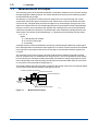


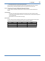


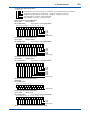
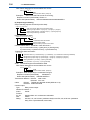
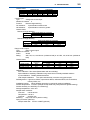
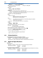

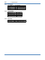
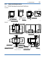
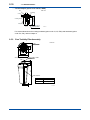
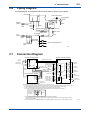

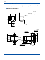
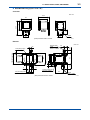

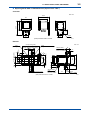
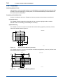
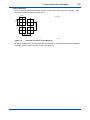
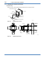

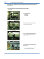
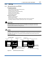
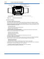
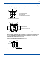

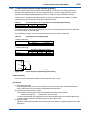
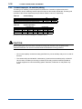

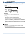

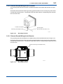
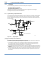
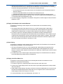
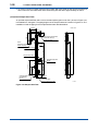
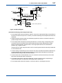
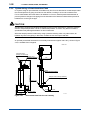

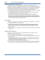
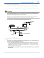
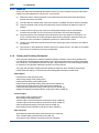
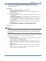
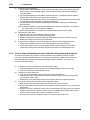
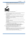
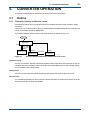
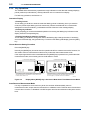
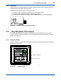

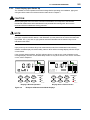
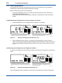
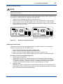
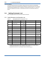
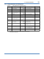
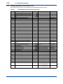


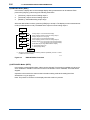
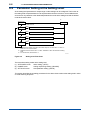
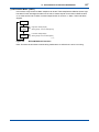
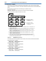
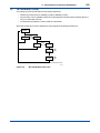
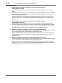
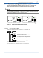
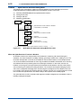
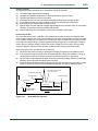
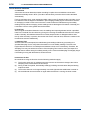
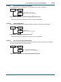
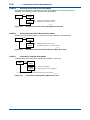
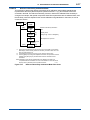
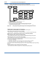
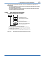
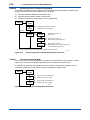
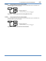

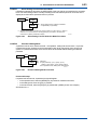
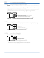
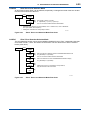
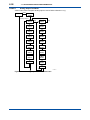
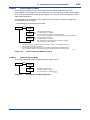
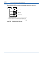


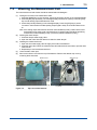
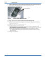

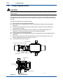
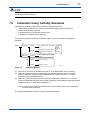
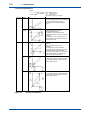


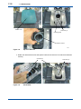
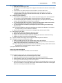


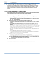

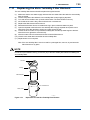

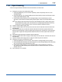
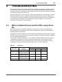
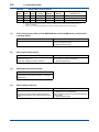

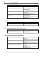
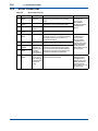
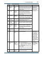

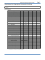
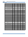
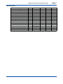
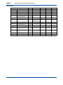


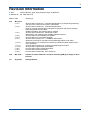

![SS400G MLSS Converter [Style:S2.2]](http://vs1.manualzilla.com/store/data/005726371_1-b873ef07ceb169a0226d293b313a67fd-150x150.png)