Transcript
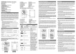
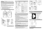
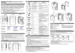
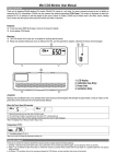
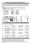
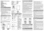
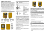
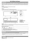
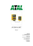
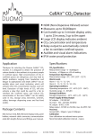
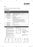
CO2 Controller Operating Instructions
3. Connection Diagram
8. Installation Instructions
Model: ZGh213
1. Product Instruction
Thank you for selecting the ZGh213 wall mount CO2 controller. By using the
CO2 controller as an indicator, you can easily measure the current CO2
concentration together with the temperature. The wall mount CO2 controller
can be used in greenhouses, hydroponics rooms, and other places where not
only plant health is important, but also the safety and comfort of the botanist
who is caring for the plants are held in high regard as well.
ZGh213 CO2 controller is cost-effective and has many features:
1. Dual Beam NDIR (Non-Dispersive Infrared) technology is used to measure
CO2 concentration up to 3,000ppm (0-10,000ppm, optional) (parts per
million) and temperature.
2. Built-in Photo Sensor.
3. Relay output can automatically control a CO2 generator or bottled CO2 to
produce CO2 in confined spaces.
2. Package Content Check & Main Unit View
The ZGh213 package contains the following items:
Main Unit:
CO2 controller
Relay Socket
Note: The CO2 controller cannot control fan itself. User can connect CO2 generator or
bottled CO2 to the piggyback plug.
4. LCD Display Symbol
Symbol
Description
CO2
Concentration ppm ambient CO2 concentration
(Parts Per Million)
User Manual
Temperature
Accessories:
Screw
Meaning
6 pcs
Panel holder
Recover
Setting
1 pcs
Factory
Calibration
display the current temperature
to recover factory default settings
and cancel any customized
settings
To calibrate the CO2 sensor
when the accuracy deviates from
the actual CO2 concentration.
Setting CO2 value Setting 1,2 CO2 value
5. Function Instruction
The Photo sensor is used to detect the presence or absence of light.
The Red LED will be constantly lit when the power is supplied.
The Yellow LED: when lit, the photo sensor is active; but the controller will not
operate during periods of darkness, piggyback plug has no output, CO2
generator or bottled CO2 won’t produce CO2.
Warning: If the CO2 concentration reaches the second setting level, the Red
LED will light on the controller. Take careful action before entering the room
where it is placed, such as ventilating the space.
6. Safety Note
A. LCD display
B. Photo Sensor(control DayLight LED)
C. Red LED (Power indication)
D. Green LED(Active when CO2 (concentration is <SetPoint1 )
E. Red LED( CO2 High: CO2(concentration> SetPoint2)
F. Yellow LED (DayLight)
G. Down Button
H. Up Button
I. Sel/Ent Button
J. Power Supply
K. Piggy back style plug
L. CO2 sensor
M. Panel Holder
Radiant Innovation Inc.
Http://www.ZyAura.com
1F, No.3, Industrial East 9th Road, Science-Based Industrial Park,
HsinChu, Taiwan 300.
Warning: Your safety is very important to us. To ensure correct and safe use of
the product, please read these warnings and the entire User Manual before
using the product. Otherwise, the protection provided by the equipment may
be impaired. These warnings provide important safety information and should
be observed at all times.
1. Please handle the device carefully; do not subject the product to impact or
shock. Otherwise, this may cause the precision of the device to decrease.
2. Do not place the unit or the adaptor near a heat source. Heat can cause
distortion of the unit, which may result in an explosion or fire.
3. Do not touch the exposed electronic circuitry of the device under
any circumstances, as there is the danger of electric shocks.
4. Please use only the included power adaptor. Improper power adaptor or
power sources can cause serious damage to the product, or result in injury
or death to the user.
7. Caring For the Product
To get the most out of this product, please observe the follow guidelines.
1. Repair - Do not attempt to repair the product or modify the circuitry by
yourself. Please contact your local dealer or a qualified repairman if the
product needs servicing, including the replacement or calibration of the
sensor.
2. Cleaning - Disconnect the power before cleaning. Use a damp cloth. Do not
use liquid cleaning agents such as benzene, thinner or aerosols, as these
will damage the device.
Please carefully take out the controller, Relay Socket, 1 panel holder, user
manual, screws, from the package.
Step-by-Step Installation:
1. Choose a suitable location to install the controller. Fix the panel holder on
the wall with the four screws (included).
2. Put it on the panel holder and make sure that they are connected tightly.
3. The ZGh213 CO2 controller has one relay output: The relay cable is
pre-wired to it. The relay can control a CO2 generator or bottled CO2 to
produce CO2 in monitored space when necessary and the relay will be
triggered when the CO2 concentration below SetPoint1 and when there is
extraneous light.
Note: If the light intensity is less than the preset value (this value cannot
be set by the user), the CO2 controller will not be active, even if the CO2
level is less than SetPoint1. Only if the light intensity is higher than the
preset level will the CO2 controller become active.
4. After finishing the installation, please connect the relay socket into the
electrical supply outlet.
SetPoint2
(Second Setting Level)
Warm-Up Time
Splash Proof Grade
Operating Conditions:
Operating Temperature
Humidity Range
Default value= 1,450ppm
<60 seconds at 22°C
IP54
0°C to 50°C ( 32°F to 122°F)
0 ~ 95% RH non-condensing
Storage Conditions:
Storage Temperature
-20°C to 60 °C (-4°F to 140°F)
■Power Supply & Relay Output:
Power Supply
Voltage
AC
Frequency
Input
Power
Requirement
Relay Socket
AC adapter 110/220 VAC
100 ~ 240 VAC
50 / 60 Hz
1 W maximum @ 115 VAC 60 Hz
2 W maximum @ 230 VAC 50 Hz
One Relay output, Peak Current< 5A@ 250 VAC,
SPST. Normally Open.
11. Dimension
9. Customizing Settings
In order to meet the personal requirements, it is advisable to set up the
customizing CO2 setting when necessary.
Setting point 1:
1. Press Sel/Ent key for more than 3 second, the “SetPoint1” icon appears.
2. Press Sel/Ent key to enter Setpoint1 mode.
3: Press Up/Down key to adjust the SetPoin1 data.
4. Press Sel/Ent key to save this parameter setting, SAVE appears on the
LCD.
Note: The default SetPoint 1 is 1,000ppm.
Setting point 2:
1. Press Sel/Ent key for more than 3 second, the “SetPoint2” icon appears.
2. Press Sel/Ent key to enter Setpoint2 mode.
3: Press Up/Down key to adjust the SetPoint2 data.
4. Press Sel/Ent key to save this parameter setting, SAVE appears on the
LCD.
Note: The default SetPoint2 is 1,450ppm. The second setting level should be higher
than the first setting level when setting level parameter.
Using the Calibration function:
1. Press Sel/Ent key for more than 3 second, the “Cali” icon flash.
2. Press Sel/Ent key again to enter “Cali” mode.
3: Press Up/Down key to Select the calibration value.
4. Press Sel/Ent key more than 10 second to calibrating the device.
Using the ReFactSet function:
1. Press Sel/Ent key for more than 3 second, the “ReFactSet” icon flashes.
2. Press Sel/Ent key again to enter “ReFactSet” mode.
3: Press Up/Down key to Select “Yes” or “No”.
3. Press Sel/Ent key to save the setting after selection.
12. Fault Codes& Troubleshooting Guide
No
LCD Fault
Icon
Description
(of the fault)
1
Er3
The ambient temperature
has exceeded the
temperature range 0°C to
50°C ( 32°F to 122°F)
2
Er4
Please unplug the AC adapter and
Inaccurate measurement
reconnect it. If the “Er4” always
or the sensor has
appears, please contact the local
exceeded its expected life
dealer.
3
Er5
Er6
EEPROM System
Problem
Er8
①Please unplug the AC adapter and
reconnect. If the “Er8” still appears,
The accuracy of CO2
please contact with the local
sensor may deviate from
dealer.
the actual concentration. ②Please calibrate the unit. After
calibration if the “Er8” still appears,
please contact the local dealer.
Note: If the user sets the data or calibrates the sensor incorrectly, use the ReFactSet to
return the default factory setting like SetPoint1, SetPoint2.
10. Specification
■CO2 specification:
CO2 Specification
Measurement Range
Display Resolution
Accuracy
Repeatability
Pressure Dependence
Response Time
SetPoint1
(First Setting Level)
4
0 - 3,000ppm display (0-10,000ppm, optional)
1ppm at 0~1,000ppm; 10ppm above 1000ppm
0~2000ppm:±70ppm or ±5% of reading, whichever
Suggested Actions
This error will disappear when the
temperature returns to the range
between 0°C and 50°C (32°F to
122°F).
Please unplug the AC adapter and
reconnect it. If the “Er5, Er6” still
appears, please contact the local
dealer.
is greater >2000ppm:±7% of reading
±20ppm @400ppm
0.13% of reading per mm Hg
<60 seconds for 90% response to step change
Default value= 1,000ppm
Ref. No.:022015