1
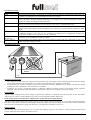
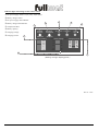
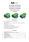
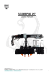
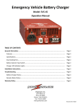
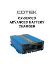
FUM – 1240CBP // FUM – 2420CBP
3 stage battery charger
User’s manual
IMPORTANT SAFETY INSTRUCTIONS
ON/OFF SWITCH
WARNING Shock and Energy Hazards
Be sure to read the safety guidelines and pay attention to
all cautions and warnings throughout the installation
procedure.
The installer is responsible for ensuring compliance with
the installation codes for your particular application.
Disconnect all sources of AC and DC power before
proceeding
AC Input
Charging Status
Remote Control
Especifications
Model
Output current
Charging type
Bulk stage
Absortion stage
Float stage
AC input voltage
Frequency
Charger efficiency
Recommended battery type and size
Remote control
Over load protection
Over temperature protection
Output reverse protection
Operating temperature
Storage temperature
Battery connection
Dimension (L x W x H) mm
Net weight (Kg)
AC input cable
FUM-1240CBP
40A
FUM-2420CBP
20A
3 stage
14.5V (±0.5V), 40A
29.0V (±1.0V), 20A
14.5V (±0.5V), 40A~4A
29.0V (±1.0V), 20A~2A
13.6V @ min. 0.5A (depends on battery
27.2V @ min. 0.25A (depends on battery
status)
status)
115V (90~135V) // 230V (180~270V)
50 / 60Hz
85%
Lead-acid batteries, 250Ah and up
Yes
Yes
Yes
Fuse blow
0ºC ~ 30ºC
-25ºC ~ 70ºC
1 positive terminal, 1 negative terminal
380 x 179 x 82
4.5
Yes
Precauciones de seguridad
1.
2.
3.
4.
5.
6.
7.
8.
9.
Do not expose the charger to rain, snow, spray, or bilge water. To reduce risk of fire hazard, do not cover or obstruct the
ventilation openings. Do not install the charger in a zero-clearance compartment. Overheating may result.
The charger is designed to be permanently connected to your AC and DC electrical systems.
Before using the charger, read all instructions and cautionary markings on the charger, the batteries, and all appropriate sections
of this guide.
Use only attachments recommended or sold by the manufacturer. Doing otherwise may result in a risk of fire, electric shock, or
injury to persons.
Do not disassemble the charger. Attempting to service the unit yourself may result in a risk of electrical shock or fire. Internal
capacitors remain charged after all power is disconnected.
The charger must be provided with an equipment-grounding conductor connected to the AC input ground.
To reduce the risk of electrical shock, disconnect both AC and DC power from the charger before attempting any maintenance
or cleaning or working on any circuits connected to the charger. Turning off controls will not reduce this risk.
Do not operate the charger if it has received a sharp blow, been dropped, or otherwise damaged in any.
To avoid a risk of fire and electric shock, make sure that existing wiring is in good condition and that wire is not undersized. Do
not operate the charger with damaged or substandard wiring.
User´s manual
-1-
FUM - 1240CBP // FUM - 2420CBP
Installation Location:
Condition
Clean
Description
Do not expose the charger to metal filings or any other form of conductive contamination. The presence of
conductive contamination can cause damage and void your warranty.
For best performance, the ambient air temperature should be between 0°C (32°F) and 30°C (95°F) – the
cooler the better. At higher ambient temperatures, the output current will be automatically reduced to
protect the charger from high internal temperatures.
The unit is intended for use in a dry location. Do not allow water or other fluids to drip or splash on the
charger. Do not mount the charger in an area subject to rain, spray or splashing bilge water.
This battery charger is Ignition Protected, so it can be installed in areas containing gasoline tanks or fittings
which usually require Ignition Protected equipment. It is safest not to install electrical equipment in these
areas.
Allow at least 10 cm (4 inches) of clearance around all sides of the charger for air flow. Ensure that the
ventilation openings on the unit are not obstructed. If mounting in a compartment, ventilate the
compartment with louvres or cut-outs to prevent overheating.
Cool
Dry
Safe
Ventilated
Close to AC
junction box
Close to batteries
Avoid the use of extended wire lengths if possible.
Avoid excessive cable lengths and use the recommended wire lengths and sizes. Undersized or overly long
cables may affect charging accuracy.
Installation illustration
DC OUTPUT
ry
tte
Ba
black
red
Explosive gas precautions
1.
2.
3.
The charger have been approved as Ignition Protected. They may be installed in areas containing gasoline tanks and fittings
which require Ignition Protected equipment. It is safest not to install electrical equipment in these areas.
To reduce the risk of battery explosion, follow these instructions and those published by the battery manufacturer and the
manufacturer of the equipment in which the battery is installed.
Working in the vicinity of lead-acid batteries is dangerous. Batteries generate explosive gases during normal operation.
Therefore you must read this guide and follow the instructions exactly before installing or using your charger.
Isolated design
The DC battery charging circuits of this charger are galvanically isolated by a transformer from the AC power circuits. This feature
reduces the risk of electric shock and helps to prevent corrosion problems in marine applications.
Fixed voltage mode (13.5V, 40A power supply for 12V; 27.0V, 20A power supply for 24V)
The fixed voltage mode setting is meant to be used as a power supply or battery eliminator. It is not meant for charging batteries.
The battery type, battery temperature, and equalize switches are all ignored in fixed voltage mode. The remote battery temperature
sensor does not compensate the voltage, but the battery over-temperature shutdown is still active.
Remote control
Remote panel: The remote panel allows you to monitor the charging progress of two batteries or battery banks, the total charge
current, and charger status from a convenient location.
User´s manual
-2-
FUM - 1240CBP // FUM - 2420CBP
Indicator lights and settings on the remote control
c DC power supply switch: 13,5V (12V); 27,0V (24V)
d Battery charger switch.
e DC power supply LED indicator.
f Battery charger LED indicator.
g Temperature fault.
h Battery capacity.
i Charging voltage.
j Charging current.
6
3
2
4
5
1
POWER
SUPPLY
BATTERY
CHARGER
SWITCH
SWITCH
Batter y Capacity
DC POWER
ON
CHARGER
ON
(12V) Batter y Voltage(24V)
15V
30V
100%
90%
80%
70%
~
0%
13V
26V
12V
24V
11V
10.5V
22V
21V
TEMP.
FAULT
Charging Cur rent
40A
30A
20A
10A
5A
2 0A
15A
10A
5A
2.5A
7
8
( Battery charger display panel )
Rev 0 - 1107
User´s manual
-3-
FUM - 1240CBP // FUM - 2420CBP