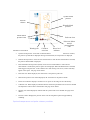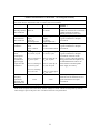
1
American Diagnostic Corporation
ADview Modular Diagnostic Station
Blood Pressure Device for Automated and Manual
Measurement
User’s Manual
About this Manual
This manual describes features and uses of the American Diagnostic Corporation ADview a non-invasive,
clinical-grade automated device to measure blood pressure, pulse rate and mean arterial pressure. Optional
modules to measure temperature and functional oxygen saturation are available, and their use is also
described in this manual.
•
This manual accompanies all the versions of the ADview :
ADview Versions*
Item Name
Item Description
ADview Battery: BP
BP device with rechargeable battery
ADview Battery: BP & Temperature
BP device with temperature and
rechargeable battery
ADview Battery: BP & SpO2
BP device with SpO2 and
rechargeable battery
ADview Battery: BP, Temperature &
SpO2
BP device with SpO2, temperature,
and rechargeable battery
* All above versions are available with a Bluetooth wireless communication option.
This document is designed to help you quickly familiarize yourself with your ADview, and subsequently, to
use it to its full potential. Dispersed throughout the body of the manual are tips, notes and warnings to
enable you to use your ADview easily, safely and effectively.
Changes and Reissues
This manual is identified as Part Number: 93-9000SM-00. Changes occurring between issues of this
document are addressed through change information sheets, addenda, or replacement pages. If none of
these accompany this manual, the manual is correct as printed.
Should you notice errors or omissions in this manual, please notify us at:
American Diagnostic Corporation
55 Commerce Drive
Hauppauge, New York 11788
USA
Phone: 631.273.9600
Fax: 631.273.9659
E-mail: [email protected]
Copyright Information
All content in this manual is the proprietary information of American Diagnostic Corporation and is
provided solely for purposes of operation, maintenance or service of the ADview. This manual and the
ADview described in it are protected under copyright law under which they may not be copied, in whole or
in part, without written consent of ADC.
ii
ADview is a registered trademark of ADC. All other trademark names are the trademarks of their respective
holders.
The information in this manual is furnished for guidance only, is subject to change without notice, and
should not be construed as a commitment by ADC. ADC assumes no liability for errors or inaccuracies that
may appear in this manual.
© 2010 ADC. All rights reserved.
iii
KEYS AND ACRONYMS
Acronyms
Acronyms commonly used in this document include:
APC
An ADC proprietary acronym for “All Purpose Cuff”
BP
Blood pressure
HR
Pulse rate
K-sound
Korotkoff sound
MAP
Mean arterial pressure
NIBP
Non-invasive blood pressure
EMR/EHR
Electronic Medical Records/Electronic Health Records
Document Key
This manual uses the following icons to call attention to specific instructions or guidance.
TIP:
A step or process that eases or enhances your use of your ADview device.
NOTE:
Indicates something you must do to use your device correctly and
effectively.
CAUTION:
Warns you that not following these instructions can cause injury, harm
or serious damage.
iv
Indications for Use
The ADview NIBP , Temperature, and Pulse Oximeter device is indicated for use in measuring and
displaying Systolic and Diastolic blood pressures, pulse rate, temperature, and functional oxygen saturation
(SpO2) of adult and pediatric patients in hospitals, medical facilities, clinics, physicians offices, and other
sub-acute environments.
User Responsibility
Your ADview product is designed to perform in conformity with the description contained in this operation
manual and accompanying labels and inserts, when assembled, operated, maintained and repaired in
accordance with the instructions provided. It is your responsibility to:
•
Check calibration of the device annually.
•
Never knowingly use a defective device.
•
Immediately replace parts that are broken, worn, missing, incomplete, damaged or contaminated.
•
Contact the nearest factory approved service center should repair or replacement become
necessary. A list of approved service centers appears on pages 44-47 or on our website at
www.adctoday.com.
Further, the user of the device bears sole responsibility for any malfunction that results from improper use,
faulty maintenance, improper repair, damage or alteration by anyone other than ADC or authorized service
personnel.
Warnings and Contraindications
Please read this manual thoroughly before starting to use your ADview. Only those clinicians trained to
measure, record and interpret vital signs should use this device.
Do not use this device on pediatric patients under 3 years old, infants, or neonates.
The ADview must be charged before using it for the first time.
For accurate blood pressure measurements, ensure that the circumference of the arm fits
within the range markings on the cuff.
v
The ADview is not intended for continuous monitoring. Although the blood pressure
cuff and cable are defibrillator proof, the temperature probe and SpO2 sensor are not. Do
not leave the device unattended while taking measurements on a patient.
Only use such accessories as are recommended for use with this device. A list of
recommended accessories is on pages 61-66.
Do not operate the ADview near flammable anesthetics or volatile vapors. An explosion
may result.
Compressing the pneumatic tubing may cause system errors.
Do not use the device if it has failed its diagnostic self test or if it displays a greater than
zero pressure with no cuff attached or a value of functional oxygen saturation or
temperature with no sensor attached.
Prevent water or other fluids from entering any connectors or vents on the device.
Should this happen, all connectors should be dried with warm air. Then check the
calibration of the device and operating functions before reusing.
Do not make repairs yourself. Equipment must be returned to ADC or authorized service
personnel for repairs. Substitution of a component different from that supplied may
result in measurement error.
vi
If the ADview is dropped or mishandled, please have it checked by a authorized service
center before bringing it back into use.
The ADview is not intended for patients connected to a cardiopulmonary bypass
machine.
At least every three months, inspect probes, cords and accessories for fraying or other
mechanical damage. Replace as necessary.
Check the calibration of your ADview at least once a year.
If Luer Lock connectors are used in the constructions of tubing, there is a possibility
that they might be inadvertently connected to intravascular fluid systems, allowing air to
be pumped into a blood vessel.
vii
TABLE OF CONTENTS
Changes and Reissues ........................................................................................................................ii
Copyright Information ........................................................................................................................ii
KEYS AND ACRONYMS .......................................................................... IV
Acronyms ................................................................................................................................................ iv
Document Key ........................................................................................................................................ iv
Indications for Use ............................................................................................................................. v
User Responsibility ............................................................................................................................. v
Warnings and Contraindications ......................................................................................................... v
TABLE OF CONTENTS ......................................................................... VIII
GETTING TO KNOW THE ADVIEW ............................................................. 1
Package Contents .................................................................................................................................... 1
The ADview Kit .................................................................................................................................. 1
Accessory Modules ............................................................................................................................ 2
Other Accessories ............................................................................................................................. 2
A Bird’s Eye View ................................................................................................................................... 3
BP module ......................................................................................................................................... 3
BP display ......................................................................................................................................... 4
Optional temperature and pulse oximetry modules ........................................................................... 5
Optional temperature and pulse oximetry displays ............................................................................ 8
Icons and Cues ........................................................................................................................................ 9
Auditory Cues ................................................................................................................................... 9
Visual Cues - Battery Icon ................................................................................................................. 9
Visual Cues - Blood Pressure Module .............................................................................................. 10
Visual Cues - Temperature Module ................................................................................................. 11
Visual Cues - Pulse Oximetry Module .............................................................................................. 12
QUICK START GUIDE ........................................................................... 13
Measuring Blood Pressure and Pulse Rate Automatically ............................................................... 13
Measuring Blood Pressure Using Sphygmode ................................................................................... 13
Measuring Temperature ...................................................................................................................... 13
Measuring Oxygen Saturation ............................................................................................................. 14
SETTING UP THE ADVIEW ..................................................................... 15
Safety Precautions ................................................................................................................................. 15
Protecting Your Patient .................................................................................................................... 15
Protecting Yourself .......................................................................................................................... 15
Protecting Your ADview ................................................................................................................... 15
viii
Mounting Your Device ......................................................................................................................... 15
Mounting the Device on a Wall ........................................................................................................ 16
Affixing the Device to a Mobile Stand .............................................................................................. 16
Placing the Device on a Tabletop ..................................................................................................... 16
First-Time Setup ................................................................................................................................... 16
Charging the Battery ....................................................................................................................... 16
Connecting Your Device .................................................................................................................. 16
Powering Up .......................................................................................................................................... 17
Selecting Temperature Unit of Measurement ................................................................................... 17
MEASURING BLOOD PRESSURE WITH THE ADVIEW .................................... 19
Prepping Your Patient .......................................................................................................................... 19
Selecting the Right Cuff ................................................................................................................... 20
Taking a Measurement ......................................................................................................................... 21
Taking an Automated Measurement ................................................................................................ 21
Taking a Sphygmode Measurement ................................................................................................. 22
K-Sounds: A Primer ............................................................................................................................. 23
MEASURING TEMPERATURE WITH THE ADVIEW ........................................ 24
Temperature Units of Measurement ................................................................................................ 24
Temperature Measurement Modes .................................................................................................. 24
Using temperature probe and probe covers ..................................................................................... 24
Taking an Oral Temperature .............................................................................................................. 25
Taking an Axillary Temperature ........................................................................................................ 25
Taking a Rectal Temperature .............................................................................................................. 26
MEASURING OXYGEN SATURATION WITH THE ADVIEW .............................. 27
Prepping the Patient ............................................................................................................................. 27
Selecting the Right Sensor ............................................................................................................... 27
Protecting Your Pulse Oximetry Sensors .......................................................................................... 27
Guidelines for Use ........................................................................................................................... 27
Measuring Oxygen Saturation with Sensor on Finger ...................................................................... 28
MANAGING READINGS ......................................................................... 30
Recalling the Last Set of Readings ...................................................................................................... 30
Clearing the Last Set of Readings ....................................................................................................... 30
MAINTAINING THE ADVIEW .................................................................. 31
Routine Maintenance ....................................................................................................................... 31
Cleaning ......................................................................................................................................... 31
Checking the Calibration of Your Device .......................................................................................... 32
Replacing the Rechargeable Battery ................................................................................................. 32
Attaching the Temperature Module ................................................................................................. 34
ix
Attaching the Pulse Oximetry Module .............................................................................................. 35
Storage, Shutdown, Transport ............................................................................................................ 36
Storage ........................................................................................................................................... 36
Moving Your Device ........................................................................................................................ 36
TROUBLESHOOTING ............................................................................ 38
Troubleshooting - Blood Pressure Module ....................................................................................... 38
Troubleshooting - Temperature Module .......................................................................................... 39
Troubleshooting - Pulse Oximetry Module ...................................................................................... 40
FAQs ...................................................................................................................................................... 42
Web Resources ...................................................................................................................................... 43
Service Centers ...................................................................................................................................... 44
For customers in the Americas ........................................................................................................ 44
For customers in Europe, the Middle East, and Africa ...................................................................... 45
For customers in Asia and the Pacific .............................................................................................. 45
SPECIAL SITUATIONS ........................................................................... 46
Special Situations .................................................................................................................................. 46
Measuring Blood Pressure in Children ............................................................................................. 46
Measuring Blood Pressure in Obese Patients .................................................................................... 46
Measuring Blood Pressure in the Presence of Arrhythmia ................................................................. 46
Measuring Blood Pressure During Pregnancy ................................................................................... 46
Measuring Blood Pressure in the Elderly .......................................................................................... 46
Measuring Blood Pressure in the Emergency Room .......................................................................... 47
Measuring Blood Pressure in the Presence of Orthostatic Hypotension............................................. 47
APPENDICES ...................................................................................... 48
Specifications ......................................................................................................................................... 48
Compliance ............................................................................................................................................ 49
Safety Requirements ....................................................................................................................... 49
EMC Statement ................................................................................................................................ 49
Symbols .................................................................................................................................................. 50
EU and FCC Regulatory Information ................................................................................................ 55
Limited Warranty ................................................................................................................................. 57
Purchasing Parts and Accessories ....................................................................................................... 58
x
GETTING TO KNOW THE ADVIEW
Your ADview is a model of functionality, offering consistent blood pressure measurements along with
reliable temperature and functional oxygen saturation readings.
Package Contents
Upon opening your kit, please ensure that all listed contents are included. If any
contents are missing or damaged, please contact ADC.
The ADview Kit
The ADview kit contains your rechargeable battery powered device. Your kit will also contain:
•
An 8-foot blood pressure hose
•
Adult and large adult size all purpose cuffs
•
A wall mounting kit or tabletop stand kit (Mobile stand shipped in separate carton)
•
A 9v AC power supply
•
A geography specific power cord
•
A CD with this manual
•
A quick start guide
To register your product, visit us at www.adctoday.com/adview and follow the links.
The ADview must be plugged in and charged before first use.
1
Accessory Modules
Accessory modules that you can purchase from your distributor or ADC to enhance usability of your
ADview include:
•
A temperature module that includes the oral/axillary probe and one box of disposable probe
covers. A rectal probe option is available separately.
•
A pulse oximetry module with an adult reusable finger sensor and 6-foot sensor extension cable.
Other Accessories
Many other accessories and sources for purchasing them are listed in the Appendix on pages 58-66. A few
to note include:
•
An APC Adult package (contains one each of the following cuff sizes: Small Adult, Adult, and
Large Adult)
•
An APC Pediatric cuff package (contains one each of the following cuff sizes: Child, Small
Adult, and Adult)
•
A rectal temperature kit compatible with the temperature module
2
A Bird’s Eye View
BP module
Automatic
button
Power button
(recessed)
Sphygmode
manual
button
Blood pressure
hose connector
Power connector
(rear panel)
Connectors on the main BP module
•
Power Connector: Connects to the power supply.
•
Blood Pressure Hose Connector: Connects to the 8-foot pressure hose.
Buttons
The buttons are used for all actions on the interface, and provide tactile feedback when pressed.
3
Buttons on the main BP module
Button Functionality for the BP Module
Button
Device Status
Action
Result
Select for less than 2
seconds
Start an automatic BP measurement.
Select for 2 to 5 seconds
Redisplay last measurement values for
all modules.
Select for more than 5
seconds
Clear last measurement values for all
modules.
Taking an
automatic or
Sphygmode BP
Select
Aborts the BP measurement in
progress.
In Calibration
Check mode
Select
Device exits Calibration Check mode
and is ready to take measurements.
Idle
Select
Inflates the cuff as long as the button
is selected.
Taking a
Sphygmode BP
Select
Re-inflates the cuff as long as the
button is selected.
Taking an
automatic BP
Select
Aborts the BP measurement in
progress.
In Calibration
Check mode
Select
Device exits Calibration Check mode
and is ready to take measurements.
Power off
Select
Turns on the device.
Power on
Select
Turns off the device.
Automatic +
Power
Power off
Hold the Automatic
button down while
selecting the Power
button.
Device enters the Calibration Check
mode.
Sphygmode
Manual +
Power
Power off
Hold the Sphygmode
button down while
selecting the Power
button.
Device enables/disables MAP mode.
Idle
Automatic
Sphygmode
Manual
Power
BP display
4
Systolic blood
pressure
Pressure
column
Diastolic blood
pressure
Mean arterial
pressure icons
Pulse rate icon
Warning icon
Information on the BP module display
Cuff/hose
error icon
Power level
indicator
Pulse rate/ Mean
arterial
pressure/Status
code
•
Systolic blood pressure: At the end of a measurement or when the last measurement is recalled,
the patient’s systolic BP is displayed. During a measurement, the cuff pressure is displayed.
•
Diastolic blood pressure: At the end of a measurement or when the last measurement is recalled,
the patient’s diastolic BP is displayed.
•
Pulse rate/Mean arterial pressure (MAP): At the end of a measurement or when the last
measurement is recalled, the patient’s pulse rate is displayed. When the MAP feature is enabled,
MAP toggles with pulse rate. If the cuff/hose error and warning icons are lit, a status code may
appear in this space. See page 39 for details.
•
Pulse rate icon: When displayed, the value below is the patient’s pulse rate.
•
Mean arterial pressure icon: When displayed, the value below is the patient’s MAP.
•
Power level indicator: Displays connection to AC power or the charge level of the battery.
•
Cuff/hose icon: When displayed, indicates that the cuff and/or pneumatic hose need to be checked
and adjusted in order to take a measurement. See page 38 for details.
•
Warning icon: When displayed, indicates that the system needs to be checked. See page 38 for
details.
•
Pressure column: Displays the pressure in the cuff. Each segment represents approximately
10mmHg.
Optional temperature and pulse oximetry modules
5
Temperature units
select (recessed)
Temperature mode
select
SpO2 sensor
connector
Buttons on the optional temperature module
•
Temperature units select: Recessed momentary switch that toggles the display between °F and
°C.
•
Temperature mode select (symbol on button: ): Momentary switch that selects oral vs. axillary
measurements for the oral temperature probe, and selects predictive vs. direct measurement
methods for all probes.
Connectors on the optional temperature module
•
Temperature unit connector: Located on the temperature
module, connects to the temperature probe housed in the
temperature probe well.
Temperature probe connector
Temperature unit connector (not shown)
6
Buttons on the optional pulse oximetry module: None
Connectors on the optional pulse oximetry module
•
SpO2 sensor connector: Connects to a SpO2 extension cable or sensor. See page 60 for compatible
accessories.
7
Optional temperature and pulse oximetry displays
Celsius icon
Fahrenheit icon
Temperature
Warning icon
Signal quality
SpO2
Warning icon
Information on the optional temperature module display
•
Temperature: At the end of a measurement, the patient’s temperature is displayed. During a
measurement, displays the probe type and related information. If the warning icon is lit, displays
the status code. See page 39 for details.
•
Celsius icon: When lit, the value below is displayed in degrees Celsius.
•
Fahrenheit icon: When lit, the value is displayed in degrees Fahrenheit.
•
Warning icon: When displayed, indicates that the system needs to be checked. See page 39 for
details.
8
Information on the optional pulse oximetry module display
•
SpO2: At the end of a measurement, the functional oxygen saturation of the patient is displayed. If
the warning icon is lit, displays the status code. See page 40 for details.
•
Signal quality: During a measurement, indicates the quality of signal from the pulse oximeter
sensor.
•
Warning icon: When displayed, indicates that the system needs to be checked. See page 40 for
details.
Icons and Cues
Your ADview is designed to provide unambiguous visual and auditory cues before, during and after a
measurement. For easy reference, all cues are tabulated in this chapter.
•
Audible cues, or beeps, identify stages in the measurement cycle.
•
Icons illuminated within a module’s display indicate measurement modes, processes or warnings.
Auditory Cues
The temperature and BP modules of the ADview are programmed with auditory cues. A listing of these
cues appears below.
NUMBER OF BEEPS…
INDICATES…
One short beep after power up or right
before powering down
The device is powered up and
ready to use or the device is about
to turn off.
One short beep after
taking a measurement
Success – measurement taken.
Three short beeps
BP measurement error. Please
check or take another
measurement.
Three long beeps
A system error has occurred.
Please refer to page 39 for
troubleshooting.
One short beep followed
by a long beep
You have aborted this BP
measurement.
Visual Cues - Battery Icon
The battery icon indicates the status of the power supply as follows.
ICON/DISPLAY
INDICATES…
9
ICON/DISPLAY
INDICATES…
Battery fully charged
Battery is charging (segments animated)
Power-off state
As the charge level drops, the segments will be
turned off in sequence from the right to the left.
The battery charge is very low. Recharge before
using. (segment flashing)
Visual Cues - Blood Pressure Module
Icons and numeric displays on your device assist you in taking quick and accurate readings.
ICON/DISPLAY
INDICATES…
The systolic BP, read in mmHg, displays
immediately below this symbol.
The diastolic BP, read in mmHg, displays
immediately below this symbol.
Unit of measurement for SYS, DIA, and MAP
Pulse rate, in beats per minute, displays
immediately below this symbol.
If this icon is lit on power-up, MAP mode is
enabled. After a measurement, this icon is lit when
MAP is displayed in the space below.
These letters are displayed in the pulse rate display
area when you are checking the device’s calibration.
Indicates an issue associated with the cuff, its
position, or connection. Please check the cuff and
hose and try again. Additionally, check page 38 for
troubleshooting details.
10
ICON/DISPLAY
INDICATES…
Warning! The device is unable to take a valid
reading. See page 38 for troubleshooting details.
A measurement is in progress. If the column is
rising, the cuff is being inflated; if the column is
falling, the cuff is deflating. Each segment lit is
approximately equivalent to 10 mmHg.
Visual Cues - Temperature Module
ICON/DISPLAY
INDICATES…
Temperature shown in degrees Fahrenheit.
Temperature shown in degrees Celsius.
The unit is taking a measurement in predictive
measurement mode.
“Traveling dash” in temperature display
Warning! There is an error in the measurement or
module. Please check the status code in the
troubleshooting section on page 39 for details and
solutions.
The device is set to measure an oral temperature.
The device is set to measure an axillary
temperature.
The device is set to measure a rectal temperature.
The unit is taking a measurement in direct
measurement mode. The display of
alternates
with the current probe temperature.
Temperature value flashes
The unit is taking a measurement in direct
measurement mode, but the reading is currently outof-range.
Temperature value flashes in an upward direction
Final measurement is greater than 109.4°F/43.0°C.
11
ICON/DISPLAY
Temperature value flashes in a downward direction
Temperature value is steady (no flashing)
INDICATES…
Final measurement is less than 86°F /30.0°C.
This is the final temperature value.
Visual Cues - Pulse Oximetry Module
ICON/DISPLAY
INDICATES…
The unit is taking a measurement.
“Traveling dash” in SpO2 display
Warning! Indicates an error in the optional pulse
oximetry module. Please refer to the
troubleshooting section on page 40.
Indicates signal strength and quality from the pulse
oximeter sensor. If there is no measurement and the
signal quality is low, try a different site or sensor.
SpO2 value
Indicates the functional oxygen saturation. This area
also displays the status code when the warning
symbol is lit.
12
QUICK START GUIDE
If the device is off, turn it on by depressing the power button on the right side.
Measuring Blood Pressure and Pulse Rate
Automatically
1.
Wrap an appropriately sized cuff (sizes are tabulated on page 20) snugly around the upper arm
midway between the elbow and shoulder.
2.
Ask the patient to stay still and quiet before taking the measurement.
3.
Press the automatic button
shown in the systolic display.
4.
In about 30-40 seconds, depending on the size of the cuff, you will hear a beep to indicate cycle
completion. The systolic and diastolic values are shown in their respective locations. If MAP
mode is enabled, the pulse rate and MAP values will alternate.
on your unit. The cuff begins to inflate and the cuff pressure is
Measuring Blood Pressure Using Sphygmode
1.
Wrap an appropriately sized cuff (sizes are tabulated on page 20) snugly around the upper arm
midway between the elbow and shoulder.
2.
Ask the patient to stay still and quiet.
3.
Press and hold the Sphygmode manual button
to inflate the cuff. Watch the pressure
displayed and release the button to start deflating the cuff at 3 mmHg/sec. Place your stethoscope
on the brachial artery to take a Sphygmode measurement.
If you see the
cuff and/or warning icon
, you will need to take
another measurement. Please refer to the troubleshooting section on page 38.
Measuring Temperature
1.
To measure temperature orally, remove the blue probe from its
holder and secure a disposable cover on it. The display shows
the type of measurement,
.
13
2.
Wait for the device to beep before placing the probe carefully under the patient’s tongue as
denoted by the heat pockets shown to the right. The posterior medial sublingual pocket is
preferred for accuracy. Hold the probe in place so that its tip maintains tissue contact. Close the
patient’s mouth. During measurement, a “traveling dash”
is displayed. In approximately 1015 seconds, you will hear a long beep and the temperature reading will display.
3.
Remove the probe from the patient’s mouth, discard the probe cover by pressing the button on the
end of the probe handle and replace the probe in its holder, ready for the next measurement.
Measuring Oxygen Saturation
1.
For the reusable finger sensor, insert the patient’s digit, index
most preferable, into the sensor. You will see a “traveling dash”
until a valid reading is available, typically in 10-20 seconds. This
reading is displayed along with the signal strength.
When selecting a sensor site, give priority to an extremity free of an arterial catheter,
blood pressure cuff or intravascular infusion.
2.
Detach the sensor carefully and replace it in the basket. At the end of the measurement, the last
valid reading will flash for 8 seconds and then be displayed for two minutes or until the next
measurement.
14
SETTING UP THE ADVIEW
Safety Precautions
As a clinically trained professional using the ADview, your responsibilities include safeguarding your
patients, yourself and your equipment. Many setup functions will be performed either only once or very
occasionally, and it is important that you pay close attention. Before you set up your ADview, please review
these safety guidelines.
Protecting Your Patient
•
While your ADview is designed for accurate, reliable vital signs measurement for adults and
children, it is not to be used on patients connected to cardiopulmonary bypass machines, patients
needing continuous monitoring, or patients under three years of age.
•
If you feel that a particular blood pressure reading is questionable, use the ADview and your
stethoscope to take a second, Sphygmode reading. If you would like confirmation for an SpO2 or
temperature reading, please use an alternate device. After taking confirmatory readings, check the
device for proper functioning.
•
Arrange the power supply and cabling so that it does not constitute a hazard to your patient, your
co-workers or yourself.
Protecting Yourself
•
Removing the cover or the back of the device can cause electric shocks. Do not attempt to service
your ADview unless you are authorized.
Protecting Your ADview
•
Do not use your ADview around flammable substances.
•
Use only ADC approved accessories to power your ADview. A listing of these is in the Appendix
on page 58.
•
Use only those batteries supplied by ADC or an authorized service representative.
•
The ADview must be placed on a stable, slip proof surface. Only recommended hardware should
be used to mount your device to a wall, pole or tabletop carrier.
•
At no point should the contents of the storage basket exceed 5 lbs. in weight.
•
Do not immerse the device in water or attempt to gas sterilize or autoclave it.
•
The reliability of your ADview depends upon conformance with the operation and service
instructions as detailed in this manual.
Mounting Your Device
For convenience, you may mount your unit on the wall or attach it to a mobile stand or a tabletop stand. A
storage basket is included and can be used to hold cuffs, boxes of probe covers for the optional temperature
module, and SpO2 sensors for the optional pulse oximetry module. All compatible accessories for mounting
your ADview can be found in the list starting on page 58. All versions of the ADview can be mounted in the
following ways:
15
Mounting the Device on a Wall
Mount the ADview on the wall in place of an aneroid
manometer. To affix your ADview to the wall:
1.
Attach the bracket to the wall using 4 wall screws, and the basket using 2 screws.
2.
Attach the wall bracket adapter to the rear panel of the BP device using the 3 screws.
3.
Position the adapter onto the rivets of the wall bracket and slide the device down until it locks
into place.
The weight of the contents of the wall-mounted storage basket should never exceed
five pounds. Please do not store heavy items in the storage basket.
Affixing the Device to a Mobile Stand
Attaching the ADview to a mobile stand facilitates portability. To mount the
ADview to the mobile stand:
1.
Assemble the mobile stand according to the manufacturer’s directions.
2.
Using the three thumb screws, secure the rear panel of the BP device to
the stand.
Placing the Device on a Tabletop
Use the ADview with the tabletop stand to make it easier to carry with you.
To mount the ADview to the tabletop stand:
1. Using the three thumb screws, secure the rear panel of the BP
device to the stand.
First-Time Setup
The ADview must be plugged in and charged before first use.
Charging the Battery
The ADview Battery is powered by a rechargeable 6V lead-acid battery or by AC power. To turn the device
on for the first time, connect the device to the power supply, then the power supply to an AC mains power
source. Leave it connected for 8 to 12 hours to fully charge the battery.
16
The charging status is indicated by the rotating sequence of lit segments
in the battery icon. When
the battery is fully charged, all segments will be lit
. A fully charged battery provides enough power
for the device to make at least 200 measurements within a 12-hour period. The battery is guaranteed to last
for 200 readings in an 8 hour period per charge.
Connecting Your Device
To maintain the easy readability and streamlined facade of your ADview, all connections are made through
the back or sides of the enclosure.
Connectors on the BP enclosure are for:
•
Blood pressure hose
•
Power supply
Connectors on the optional modules are for:
•
A pulse oximetry sensor on the pulse oximetry module
•
A temperature probe on the temperature module
To connect the ADview:
1.
For blood pressure measurements, the blood pressure hose should already be attached to the BP
device. If not, push the open end of the blood pressure hose (one without the plastic connector)
over the blood pressure hose connector on the module. Secure the end with the plastic connector
to an appropriately sized cuff by twisting the two mating connectors together.
2.
For temperature measurements, remove the tape holding the temperature probe in the well, and
place the box of probe covers in the well next to the probe.
3.
For SpO2 measurements, attach the pulse oximetry sensor to the extension cable. Flip the
retention clip forward. Then, connect the other end of the extension cable to the connector on the
module. Finally, push the clip backward over the SpO2 connector to hold the connector in the
module.
4.
Connect the power supply to the main BP module. Then, connect the power supply to an AC
mains power source. The device will turn on automatically.
Powering Up
1.
Depress the power button located on the right side of the main enclosure. The power-up sequence
begins. All display segments light up for three seconds. A short beep indicates that the ADview is
ready.
2.
Check the status of the power level indicator. If the power level indicator shows one segment
flashing, connect the device to the power supply before using. You are now ready to use your
ADview.
Selecting Temperature Unit of Measurement
17
With the device powered on, select the unit of measurement for temperature by depressing the recessed
button on the side of the temperature module to toggle between the °C and °F icons. The selected icon will
be lit in the display and becomes your default selection.
Bluetooth Wireless Communication
If your ADview has the optional Bluetooth wireless communication capability, please contact your IT
administrator for configuration with your EMR/HER system or communication network.
18
MEASURING BLOOD PRESSURE WITH THE ADVIEW
Your ADview device is designed to take accurate blood pressure readings by the oscillometric method.
Systolic pressures from 60 to 270 mmHg and diastolic pressures from 30 to 170 mm Hg lie within the
range of your device. In most cases, you will be able to take accurate blood pressure (BP) and pulse rate
(HR) measurements within 30-40 seconds.
Steps in taking a BP measurement are:
•
Prepping the patient and attaching the cuff
•
Taking the measurement
Prepping Your Patient
Ensure that the patient:
•
Is not wearing any constricting clothing on the selected arm.
•
Has no injury or tissue damage on the selected arm.
•
Keeps the cuffed arm at heart level.
•
Keeps the cuffed arm motion-free and relaxed without any muscle tension in the biceps and
triceps during the measurement.
•
Does not cross his/her legs for the measurement.
Keep aware of current practices as recommended by the American Heart Association, British Hypertension
Society, and other medical practice associations.
1.
Ready the patient into a sitting
, standing
patient’s BP can vary with position.
, or supine
position. Remember that a
The stress of being in a clinical situation often causes patients to undergo ‘white coat
hypertension,’ leading to higher-than-normal readings. Help your patient to relax as
you prepare to take the measurement.
19
Selecting the Right Cuff
Your device comes with durable two-piece All Purpose Cuffs (APC) from ADC. Cuffs are available in a
range of sizes, from Child to Thigh. Note that your ADview works optimally with APC cuffs.
Using the table below, select a cuff you estimate to be of the right circumference:
2.
Wrap the cuff around the patient’s upper arm midway between the elbow and the shoulder.
3.
Ensure the ARTERY arrow is over the brachial artery, between the biceps and triceps muscles on
the inside of the arm.
4.
Use the range indicator
and the INDEX line on the inside of the cuff to check that the
arm circumference falls within the specified range of the cuff. If the arm is within range, this cuff
size is correct for your patient. If the measurement is outside the RANGE indicator, use the
appropriate larger or smaller cuff and re-check.
Using a cuff that is too small, commonly called undercuffing, can result in
overestimating a patient’s BP. Using a cuff that is too large, or overcuffing, can result
in underestimating a patient’s BP. For most accurate results, take care in selecting the
appropriate size cuff for your patient.
5.
Ensure that the BP pressure hose is connected to the cuff. Confirm that the hose is neither
compressed nor kinked.
6.
Ask the patient to stay still and quiet before taking the measurement.
Do not place the cuff on an arm currently being used for other procedures such as
intravenous infusions or oximetry readings.
20
Taking a Measurement
The ADview allows you to take BP measurements automatically like a monitor or manually like a
sphygmomanometer using manual Sphygmode™.
In automatic mode, the cuff inflates and deflates automatically. Initial inflation reaches a cuff pressure of
160 mmHg; the cuff then re-inflates as necessary to obtain a reading. Deflation is optimized to reduce
measurement time and obtain an accurate result.
In manual Sphygmode, you inflate the cuff manually using the Sphygmode MAN button in place of an
inflation bulb of a sphygmomanometer. When you release the Sphygmode MAN button, the cuff
automatically deflates at the AHA recommended rate of 3mmHg/sec. Simply use your stethoscope to
determine your patient’s blood pressure.
Taking an Automated Measurement
1.
With the patient prepped as described earlier (page 19), and the device powered on, depress the
automatic button that is located in front of the BP module and denoted by the cuffed arm icon
. The cuff inflates to approximately 160 mmHg, as indicated in the systolic area of the
display.
2.
Once the cuff pressure reaches its target, the device controls the deflation and, in some instances,
re-inflation of the cuff in order to accurately measure BP. The cuff pressure displays in the
systolic area and is also indicated by the vertical LED bar to the left. When you hear a single
short beep, indicating the end of the measurement cycle, read the systolic and diastolic pressures,
displayed under the SYS and DIA symbols, and the pulse rate, displayed under the
symbol.
By default, your ADview measures systolic and diastolic BP, and HR. To obtain a
Mean Arterial Pressure (MAP) reading, hold down the Sphygmode manual button
Want a MAP
reading? NOTE:
MAP available
outside USA
only
3.
as you toggle power to on. On power up, the MAP icon lights up on the LED
display. Now, once measurements are complete, the display will alternate between HR
and MAP. To exit MAP mode, power the device off and again hold down the
Sphygmode manual button
as you toggle power to on. On power up, the MAP
icon will flash and disappear. MAP will no longer be displayed.
If there is an error in obtaining a measurement, indicated by three beeps, please refer to the
troubleshooting tips on page 38 and take the appropriate remedial measure.
21
Taking a measurement on each arm helps rule out dissecting aneurysms, coarctation of
the aorta, vascular obstruction and possible errors in measurement.1
You can find more tips like this in the American Heart Association’s current scientific
statement on recommendations for blood pressure measurement.
Taking a Manual Sphygmode Measurement
1.
With the patient prepped as described earlier (page 19), and the device powered on, palpate the
brachial artery at the antecubital fossa. Place your stethoscope over this space.
2.
Press and hold the Sphygmode manual button
mmHg higher than the patient’s systolic pressure.
3.
Once the cuff has been inflated to the desired level, release the Sphygmode manual button. The
cuff begins to deflate at approximately 3mmHg/sec and the device displays the cuff pressure.
4.
While listening to your stethoscope, note the systolic and diastolic pressures corresponding to the
first and last Korotkoff sounds (K-sounds) heard.
Press the Sphygmode manual button
Press the automatic button
until you inflate the cuff to a level at least 30
to re-inflate the cuff.
if you need to rapidly release all the air from the cuff.
1
Circulation. AHA Scientific Statement: Recommendations for Blood Pressure Measurement in Humans
and Experimental Animals, Part 1: Blood Pressure Measurement in Humans: A Statement for Professionals
From the Subcommittee of Professional and Public Education of the American Heart Associations Council
on High Blood Pressure Research. Thomas G. Pickering, MD, DPhil; John E. Hall, PhD; Lawrence J.
Appel, MD; Bonita E. Falkner, MD; John Graves, MD; Martha N. Hill, RN, PhD; Daniel W. Jones, MD;
Theodore Kurtz, MD; Sheldon G. Sheps, MD; Edward J. Roccella, PhD, MPH, 2005;111:697-716.
22
K-Sounds: A Primer
Korotkoff sounds, commonly called K-sounds, are the sounds you detect through your stethoscope when
you measure blood pressure with a sphygmomanometer or an aneroid device. Named for the Russian
physician who identified them, there are five phases of K-sounds, each phase characterized by a distinct
volume and quality of sound.
K-sounds are heard through the stethoscope as the blood pressure cuff deflates. The first sound, K-1, is
heard when cuff pressure equals systolic pressure. K-1 is a sharp, tapping sound.
The K-2 phase is characterized by a swishing sound, caused by the swirling currents in the blood as the
flow through the artery increases.
In the K-3 phase, there is a resumption of crisp tapping sounds, similar to those heard during phase 1.
An abrupt muffling of sound identifies K-4, the fourth phase.
The end or fifth phase is the point at which sounds cease to be heard altogether.
Systolic pressure is registered at K-1 and diastolic at K-5.
K-4 or K-5? There exists some debate about whether K-4 or K-5 should be recorded
as the diastolic BP. In most cases, K-5 is preferred. However, if the sound persists even
after the cuff is completely deflated, it is recommended that K-4 be recorded as the
diastolic blood pressure.2
You can find more tips like this in the British Hypertension Society’s current
guidelines for management of hypertension.
2
B Williams, NR Poulter, MJ Brown, M Davis, GT McInnes, JF Potter, PS Sever, S McG Thom, British
Hypertension Society Guidelines, Guidelines for management of hypertension: report of the fourth working
party of the British Hypertension Society 2004 – BHS IV, Journal of Human Hypertension, 2004 18, 139185.
23
MEASURING TEMPERATURE WITH THE ADVIEW
Your ADview device can measure temperature with the optional temperature module. This module enables
you to take rapid, accurate temperature measurements ranging from 86°F-109.4°F. Typically, predictive
readings are obtained within ten to fifteen seconds, and direct readings within two minutes. The module is
equipped with the temperature probe for oral/axillary measurement, color-coded blue. A rectal probe that
is color-coded red is optionally available.
Temperature Units of Measurement
The device displays the temperature measurement in:
•
Celsius
•
Fahrenheit
To choose a unit of measurement, depress the recessed button on the left side of the temperature module.
The icon for the selected unit is illuminated. This is now the default selection.
Temperature Measurement Modes
The device can measure temperature via three modes:
•
Oral, indicated by
•
Axillary, indicated by
•
Rectal, indicated by
on the display and measured using the blue probe
on the display and measured using the blue probe
on the display and measured using the red probe
All three modes can be used for both predictive and direct measurement. In the default predictive mode,
your ADview predicts temperature in 10-15 seconds with an accuracy of +/- 0.2 °F (+/- 0.1°C). When a
fever is detected, the measurement may last longer. In direct mode, the display continually updates until a
stable reading is reached. This mode is used in certain difficult conditions when a predictive reading is not
preferred or possible.
Axillary and rectal modes are preferred for children and compromised patients.
Using temperature probe and probe covers
In addition to the safety instructions for your ADview, here are some additional tips on using the probe and
probe covers for the optional temperature module:
•
Use only ADC by SunTech supplied probe covers with this device.
•
The device and probe covers are non-sterile. Do not use on abraded tissue.
•
To limit cross contamination, use blue probes for taking oral and axillary temperature only. Use
red probes for rectal temperatures only.
24
•
Dispose used probe covers in accordance with current medical practices or local regulations
regarding disposal of infectious, biological medical waste.
•
Note that proper placement of the probe is essential to the accuracy of the measurement.
Taking an Oral Temperature
1.
Remove the blue probe from its holder and secure a disposable cover on it. The probe preheating process begins with the flashing display of the type of measurement,
.
2.
After a few seconds, the device will beep to signify that the
probe is ready for placement. After the beep, place the probe
carefully under the patient’s tongue as denoted by the heat
pockets shown to the right. The posterior medial sublingual
pocket is preferred for accuracy. Hold the probe in place so that
its tip maintains tissue contact. Close the patient’s mouth.
During measurement, a “traveling dash”
is displayed.
3.
After 10-15 seconds, a long beep signals the end of the
measurement cycle. The temperature will display for two
minutes or until you initiate a new measurement.
4.
Remove the probe from the patient, discard the probe cover by pressing the end of the probe
handle, and return the probe to the probe holder. Note the temperature reading.
By default, the predictive method is selected. To select direct measurement from the
start, press the temperature mode select button located on left side of the temperature
module for three seconds or until you hear two short, quick beeps. When using direct
measurement, the display will alternate displaying “dir” and the current probe
temperature. A long beep signals the final temperature result.
Taking an Axillary Temperature
1.
Remove the blue probe from its holder and secure a disposable
cover on it. The probe pre-heating process begins with the
flashing display of the type of measurement,
.
2.
Briefly (less than 2 seconds) press the temperature mode select
button until it displays
for axillary.
3.
After a few seconds, the device will beep to signify that the probe is ready for placement. After
the beep, lift the patient’s upper arm and place the probe high under the patient’s axilla. Apply
pressure gently to assure good contact between the probe and axilla, and make sure there is no
interference such as clothing. Hold the probe in place so that its tip maintains tissue contact.
Place the arm by the patient’s side. During measurement, a “traveling dash”
is displayed.
Note that proper placement of the probe is essential to the accuracy of the
25
measurement.
4.
After 10-15 seconds, a long beep signals the end of the measurement cycle. The temperature will
display for two minutes or until you initiate a new measurement.
5.
Remove the probe, discard the probe cover and place back in the probe holder. Note the
temperature reading.
Taking a Rectal Temperature
1.
Remove the blue probe and well by sliding the pieces upward until they detach.
2.
Place the red probe in the holder of the red well and the probe
connector in the notched space as shown to the right (see page 35
for detailed instructions). Slide the red well vertically onto the
back of the module thus replacing the blue well.
3.
space/
Probeand
connector
Assist patient into a prone Notched
(facedown)
position
ensure that the
patient is relaxed.
4.
Remove the red probe from its holder and secure a disposable cover on it. The probe pre-heating
process begins with the flashing display of
.
5.
After a few seconds, the device will beep to signify that the probe is ready for placement. After
the beep, separate the patient’s buttocks and apply a thin coat of water-based lubricant for smooth
entry of the probe. Insert the probe gently 1 cm inside the sphincter. Tilt the probe to keep it in
place and hold it in position to ensure tissue contact. During measurement, a “traveling dash”
is displayed.
Note that proper placement of the probe is essential to the accuracy of the
measurement.
6.
After 10-15 seconds, a long beep signals the end of the measurement. The result will be displayed
for two minutes or until you initiate a new measurement.
7.
Remove the probe, discard the probe cover and place back in the probe holder. Note the reading.
If the temperature reading is out of range, the device will beep and flash the limit that
is exceeded. So, if the reading is greater than 109.4°F (43.0°C), “109.4” or “43.0” will
flash on the display followed by a sequence of rising LED’s. If the reading is less than
86.0°F (30.0°C), “86.0” or “30.0” will flash on the display followed by a sequence of
falling LED’s.
26
MEASURING OXYGEN SATURATION WITH THE
ADVIEW
The ADview optional pulse oximeter module measures functional oxygen saturation ranging from 40% to
100%. A signal strength display assists the clinician in the proper placement of the sensor.
The ADview is a spot check device and is not used for patient monitoring. Therefore,
there are no SpO2 alarms.
Steps for measuring functional oxygen saturation:
•
Prepping the patient and affixing the sensor
•
Taking a reading
Prepping the Patient
Selecting the Right Sensor
Your choice of sensor is affected by many factors including:
•
Patient’s body weight
•
Patient activity
•
Infection control concerns
For most patients greater than 30kg, use an adult sensor; for patients 10-50kg, a
pediatric sensor may provide better fit.
Protecting Your Pulse Oximetry Sensors
In addition to the safety instructions for your ADview, here are some additional tips on caring for the sensor
of the optional pulse oximetry module:
•
To prevent damage, do not autoclave or immerse the sensor in liquid.
•
For peak performance and accurate measurements, do not expose the sensor to excessive ambient
light, electromagnetic interference, dysfunctional hemoglobin, low perfusion, intravascular dyes,
finger nail polish and long or artificial finger nails.
•
Do not use a damaged sensor as it may cause patient injury or equipment failure.
•
The use of this sensor is contraindicated in patients with allergies to adhesive tape.
Guidelines for Use
27
•
When selecting a sensor site, give priority to an extremity free of an arterial catheter, blood
pressure cuff or intravascular infusion line.
•
Clean reusable sensors after use.
•
Ensure that the optical components of the sensor are properly
affixed to the patient and aligned.
•
Artificial nails, or dark shades of nail polish, may reduce light
transmissions and affect pulse oximetry accuracy. Clean off nail
polish or detach artificial nails before applying the sensors.
•
Secure sensor cable firmly but lightly at the base of the finger.
•
Inspect the sensor application site at least every 6 to 8 hours to ensure correct sensor alignment
and skin integrity. Patient sensitivity may vary due to medical status or skin condition.
Discontinue use of adhesive tape strips if the patient exhibits an allergic reaction to the adhesive
materials.
Measuring Oxygen Saturation with Sensor on
Finger
For best results, clip the sensor on the index, middle or ring finger, avoiding the little
finger or thumb.
1.
For the reusable finger sensor, insert the patient’s digit, index
most preferable, into the sensor. Ensure that the tip of the digit
touches the rear guide posts of the sensor and the sensor cable
extends along the top of the patient’s hand. Secure sensor with
wrap, tape or bandage.
SpO2 measurement will begin automatically. Once the SpO2 determination begins, a “traveling
dash”
will be displayed until a measurement is determined, usually in 10 seconds. This
reading will be updated once per second. SpO2 can be measured without interruption for up to 10
minutes. Along with the functional oxygen saturation value, the signal strength will also display.
2.
When you remove the sensor from the patient’s finger, the display will flash the last measurement
for 8 seconds. The measurement will then be displayed for 2 minutes or until another
measurement is made. Note the patient’s reading and confirm normal venous return.
After 10 minutes of continuous measurement, the measurement is automatically
terminated and status code “01” is displayed. To view the last measurement prior to
automatic termination, press and hold the automatic button
28
for more than two
seconds (see page 30 for details).
29
MANAGING READINGS
Recalling the Last Set of Readings
To redisplay the last set of readings, depress the automatic button
on the BP module for more than two
seconds until the last reading is displayed. If your ADview has temperature and/or pulse oximetry modules,
the last set of readings includes these readings as well. If the last attempted reading resulted in an error
and/or warning, then this will be displayed. The device will display dashes if no reading is in memory, a
reading was aborted or, the previous BP was a Sphygmode measurement.
For the pulse oximetry module: In the event of the 10-minute measurement timeout, the module will
terminate the measurement and status code “01” will display on the main module. The last valid reading
recorded at the end of the ten-minute period will be the recalled reading.
Clearing the Last Set of Readings
To clear the values from the last automatic BP measurement and the accessories, press and hold the
automatic button
more than 5 seconds. Previous values will be displayed momentarily. Then the
display blanks. On redisplay you will see dashes for all the values that have been cleared.
Your ADview displays the most recent set of readings for two minutes. If patient
privacy is a concern, you can clear these readings from the display before collecting
vital signs from another patient.
Bluetooth Wireless Transmission of Readings
If your ADview has the optional Bluetooth wireless communication capability you may be able to transmit
the readings into your EMR/EHR system or communication network. Contact your IT administrator or
EMR/EHR vendor for support on configuring your ADview for Bluetooth wireless communication.
30
MAINTAINING THE ADVIEW
Routine Maintenance
Establishing simple care guidelines helps protect the performance and life of your ADview. On a routine
basis, you should inspect the device, cables and pneumatic hoses for cracks, fraying or kinks and
immediately replace any damaged parts.
Remember to check the calibration of the BP module annually. If available, a biomedical technician may
help in maintaining your equipment.
Cleaning
Cleaning the Device
1.
Wipe the device with a soft, damp cloth to remove surface dust and dirt.
The ADview device cannot be sterilized.
Never immerse the device in any fluid or attempt to employ cleaning fluids or solvents.
Cleaning the Cuffs
1.
Between uses, wipe cuff sleeves and the insides of cuffs with a medical grade cleaning agent.
2.
Periodically, remove the bladders and machine-wash the cuffs in cold water.
3.
Line dry.
Cleaning the SpO2 Sensor
1.
Clean sensor and clips with a soft cloth dampened with water, a mild soap solution, or isopropyl
alcohol.
2.
Remove all tape residues by rubbing off.
3.
Dry sensor and clips thoroughly before re-use.
Never immerse sensor and clips in fluids. Do not pour or spray any liquids on them
either. Caustic or abrasive cleaners will cause permanent damage.
31
Prying the finger clip sensor to an angle greater than 90° can permanently damage its
casing.
Checking the Calibration of Your Device
It is recommended that you check the BP calibration of your ADview once a year. To check calibration:
1.
Start with the device powered off. While holding down the automatic button
on the front of
the BP module, toggle on the power button on the right side of the main enclosure. The “CAL”
message is displayed in the pulse rate display to indicate that the system is in the calibration
mode. During this mode, the system pressure displays in the systolic BP display area.
2.
Using a T-connector, connect a calibrated pressure reference and control, such as a manometer
and inflation bulb, to the pressure hose connector of the ADview. Contact ADC customer support
for details on ordering the calibration kit which includes a T-connector.
Compare the pressure reference to the ADview throughout the pressure range, 0 to 270mmHg. If
the difference between the pressure reference and the ADview is no larger than 2mmHg, the
ADview is calibrated correctly for operation. If the ADview needs calibrating, contact an
authorized service center on page 44.
3.
4.
Exit the calibration check by pressing the automatic button
again. Once the display shows
dashes as the systolic BP, you are now ready to take a measurement.
It is recommended that you check the temperature calibration of your ADview temperature module
annually. A Calibration Plug (see page 58 for details) is available to check accuracy of the technology. It
replaces the regular probe and verifies the accuracy of the temperature electronics. Replace the
temperature module if error is greater than +/-0.1 C. To check the calibration:
1. Remove the Temperature Well from the Temperature Module.
2. Replace the Temperature Probe with the Calibration Plug.
3. Replace the Temperature Well.
4. Initiate a measurement by inserting and removing the Temperature probe from the well.
5. Verify the accuracy of the measurement.
Probe accuracy can be checked by using the thermometer as you would on a patient in any mode with a
cover, but place it in a calibrated water bath. Direct mode is accurate to +/- 0.1 C of the calibrated water
bath temperature. Predictive mode accuracy is accurate to +/- 0.2 C of the calibrated water bath
temperature.
Replacing the Rechargeable Battery
Replace the battery:
•
According to your regular maintenance schedule.
•
When the battery no longer charges.
•
After heavy use, if necessary.
32
To replace the battery:
1. Remove the four screws securing the battery bay door.
2. Carefully remove the battery from the battery bay, being careful not to pull on the wires
attached to the battery terminals.
3. Disconnect the wires from the battery terminals.
4. The rechargeable battery contains lead. Please dispose of the old battery properly.
5. Connect the wires to the terminals of the replacement battery, ensuring the red wire is
attached to the red terminal and the black wire to the black terminal. If the wires are reversed,
no damage will occur, however the ADview will not operate. Be sure to use ADC item
number 9000BAT for the replacement battery in order to maintain optimum performance.
6. Re-secure the battery bay door with the four screws removed in step 1.
7. Connect the power supply to turn the device on and charge the replacement battery fully
before using.
If the rechargeable battery is disconnected for any reason, the device must be
connected to AC mains power via the power supply before the unit will turn on; this is
required even if the battery has been properly reconnected.
Disposal
This symbol indicates the device contains materials (such as electrical components) which are
hazardous. Please return to ADC for disposal.
33
Attaching the Temperature Module
Should you need to attach or remove the temperature module; the following instructions give an overview
of its attachment to the BP module. The temperature module attaches to the top of the BP module. It is
made up of the following two pieces:
A
•
Part A with the display.
•
Part B, the probe holder, which holds the temperature
probe and probe cover box.
B
1.
Using the power button on the right side of the BP module, ensure that the ADview is off.
2.
Remove the cover plate from the top of the BP module.
3.
Slide part A of the temperature module along the guides on the top of the
BP module from front to back until it snaps into place. All the segments
of the temperature module display will light when the modules have
been connected correctly.
34
A
4.
Attach the temperature probe connector to part B as follows: with the black surface facing
downward, hold the probe connector end against the notches on the probe holder, as shown in red
(step 1 shown below).
5.
Rotate the connector upwards until it snaps securely into place (step 2 shown above). The black
surface faces outward and the cord extends upward.
6.
Slide part B onto part A as shown (this connects the temperature probe
connector to the temperature unit connector), and insert the temperature probe
into the well.
7.
B
Turn the device on using the power button on the right side of the BP module.
At the end of the start-up sequence, the temperature module display will be
blank except for the appropriate temperature unit icon (°F or °C). A short beep A
indicates that the ADview is ready.
Temperature unit
connector (not
Note: If the temperature module does not appear to be working properly, cycle the power several
times
shown)
using the power button on the right side of the BP module. This will “synchronize” all the modules.
The modules are synchronized when, after you turn the power on, all segments on all module displays
light simultaneously for 3 to 5 seconds, followed by a short beep, and all displays go to their “ready”
state (BP: battery icon and middle segments of the systolic value are lit; Temperature: appropriate
temperature units icon is lit; Pulse Oximetry: the “%SpO2” icon is lit).
Attaching the Pulse Oximetry Module
Should you need to attach or remove the pulse oximetry module; the following instructions give an
overview of its attachment to the BP module. The pulse oximetry module attaches to the bottom of the BP
module.
1.
Using the power button on the right side of the BP module, ensure that the ADview is off.
2.
Remove the cover plate from the bottom of the main BP module.
35
3.
Slide the pulse oximetry module along the guides on the bottom of the main BP
module from front to back until it snaps into place. All the segments of the pulse
oximetry module display will light when the modules have been connected
correctly.
4.
Turn the device on using the power button on the right side of the BP module.
At the end of the start-up sequence, the pulse oximetry module display will be
blank except for the “%SpO2” symbol.
5.
Turn the device off. Connect the adult reusable sensor to the 6’ extension cable and then the
cable to the connector on the module. Secure the cable to your device using the retention clip.
6.
Turn the device on. All display segments light up for three to five seconds. A short beep
indicates that the ADview is ready.
Note: If the pulse oximetry module does not appear to be working properly, cycle the power several times
using the power button on the right side of the BP module. This will “synchronize” all the modules. The
modules are synchronized when, after you turn the power on, all segments on all module displays light
simultaneously for 3 to 5 seconds, followed by a short beep, and all displays go to their “ready” state (BP:
battery icon and middle segments of the systolic value are lit; Temperature: appropriate temperature units
icon is lit; Pulse Oximetry: the “%SpO2” icon is lit).
Storage, Shutdown, Transport
Storage
The ADview must be stored between -20°C (-4°F) and 55°C (131°F). Relative humidity must be less than
90%.
If you are storing the ADview Battery for 30 days or longer, it is recommended that you disconnect the
battery from the device.
Moving Your Device
To pack your device for repair or transport:
36
1.
Detach the cuff, temperature probe, SpO2 sensor, power supply, and other ancillary products from
the device.
2.
Disconnect the battery and remove it from the device.
3.
Place the device in the original shipping carton, preferably with its original packing material.
4.
Ensure that the device will be kept at between -20°C (-4°F) and 55°C (131°F) and in relative
humidity less than 90% during transshipment.
37
TROUBLESHOOTING
The troubleshooting chart provides pointers on diagnosing issues associated with error or status codes.
Problem: The ADvew will not power on.
Solutions:
1. The ADview must be plugged in to charge before first use.
Problem: My ADview is not communicating with my EMR/EHR system or network
Solutions:
1. Be sure your ADview is equipped with the Bluetooth option.
2. Your ADview and wireless system must be configured to communicate. Refer to your
EMR/EHR operator’s manual or contact your IT administrator or EMR/EHR provider.
3. You may need to move your ADview closer to the wireless system. While the
Bluetooth capability on the ADview has been rated up to a maximum range of 100 m,
be sure to minimize walls, structures and other obstacles that may impede wireless
connectivity.
Troubleshooting - Blood Pressure Module
Problem: Wrong size cuff, Misplaced cuff, or Blocked brachial artery
Solutions:
1. Check that the cuff is in the correct position.
2. Check that the cuff is properly tightened.
3. Check that there is no excessive clothing between the arm and the cuff.
4. Check that the cuff applied is of the correct size.
5. The patient may have been moving too much.
6. Take another BP reading.
Problem: Too much patient or environment motion or conditions causing tremors
Solutions:
1.
Check that the cuff is in the correct position.
2.
The patient may have been moving too much.
3.
Take another BP reading.
.
Problem: Air leak, Loose cuff, or Blocked or pinched hose
Solutions:
1.
2.
3.
4.
5.
Check that the hose has no sharp bends or is pinched.
Check that the patient is not lying on the cuff.
Check that the cuff is in the correct position.
Check that the hose is connected to the system and the cuff.
Check that the cuff is properly tightened.
38
6.
7.
8.
9.
Check that the correct size cuff is being applied.
Check that the cuff is not leaking air.
Check that the hose connections are not damaged or loose.
Take another BP reading.
Status Codes: 800, 900, 910, 970, 980, or 990
Problem: System error
Solutions:
1.
Take another measurement.
2.
If this is unsuccessful, power down, then power up the unit using the power button on the
right side of the unit. If the error does not recur immediately, take another measurement.
3.
If the error recurs, remove power from the unit (unplug any power supplies and remove
the battery, if there is one), then reconnect the power. If the error does not recur
immediately, take another measurement.
4.
If the error recurs, contact ADC or an authorized service center.
Troubleshooting - Temperature Module
Status Code: 5
Problem: Temperature probe missing or outside of well
Solutions:
1. Remove and then place the probe in the well.
2. Ensure that the temperature well (the rear portion of the temperature module) is well
seated on the display. Along the top of the module, the edge of the well should be flush
with the display. Remove and carefully slide the well onto the display.
When properly fixed, the error should no longer be displayed. Take a new measurement.
Status Code: 10
Problem: Defective temperature probe
Solutions:
1. Remove and then place the probe in the well.
2. Ensure that the temperature well (the rear portion of the temperature module) is well
seated on the display. Along the top of the module, the edge of the well should be flush
with the display. Remove and carefully slide the well onto the display.
When properly fixed, the error should no longer be displayed. Turn the device off. After it
has shut down, turn it on. The error should no longer be displayed. Take a new measurement.
Status Code: 15
Problem: Stuck button
Solution: Depress the Temperature units select button and/or the Temperature mode select
button until the button becomes unstuck. When the button is unstuck, the error will no longer be
displayed. If you cannot un-stick the button, contact ADC or an authorized service center.
39
Status Code: 20
Problem: Hardware error
Solutions:
1. Take another measurement.
2. If this is unsuccessful, power down, then power up the unit using the power button on the
right side of the unit. If the error does not recur immediately, take another measurement.
3. If the error recurs, remove power from the unit (unplug any power supplies and remove
the battery), then reconnect the power. If the error does not recur immediately, take
another measurement.
4. If the error recurs, contact ADC or an authorized service center.
Troubleshooting - Pulse Oximetry Module
Status Code: 01
Problem: Measurement time-out. The measurement time exceeded the 10-minute
time limit.
Solution: Remove the sensor from the patient. Redisplay the last measurement prior to the
timeout, or take a new measurement by placing the sensor on the patient.
Status Code: 02
Problem: Poor sensor position (signal is inadequate for a reliable measurement)
Solution: Adjust position of sensor on patient by placing sensor on opposite hand or ear or
alternate site. Avoid fingers with nail polish or artificial nails.
Status Code: 05
Problem: The sensor has been disconnected from the device.
Solution: Reconnect the sensor. If you wish, you may leave the sensor disconnected as this
code is only displayed once at the time the sensor is disconnected.
Status Code: 10
Problem: Defective sensor
Solution: Replace the sensor and take a new measurement.
Status Code: 20
Problem: Hardware error
Solutions:
1. Take another measurement.
2. If this is unsuccessful, power down, then power up the unit using the power button on the
right side of the unit. If the error does not recur immediately, take another measurement.
3. If the error recurs, remove power from the unit (unplug any power supplies and remove
the battery), then reconnect the power. If the error does not recur immediately, take
another measurement.
4. If the error recurs, contact ADC or an authorized service center.
40
Problem: Inadequate signal strength
Solution: If there is no measurement and the signal quality is low, try a different site or sensor.
Avoid fingers with nail polish or artificial nails. If there is no improvement in signal quality, then
discontinue use.
41
FAQs
Can I obtain replacement copies of the ADview CD and manual?
Copies of the ADview manual are available through the Customer Service area of our website. To download
the manual, please visit www.adctoday.com/adview. For a replacement CD, please email Customer
Service at [email protected]
How do I clean the ADview device?
The ADview requires only minimal cleaning. Wipe it down occasionally with a soft, damp cloth. Never
immerse the device or apply cleaning fluid or solvents.
How do I install the rechargeable battery in the ADview?
Remove the battery bay cover and position the rechargeable battery within, ensuring proper alignment of
polarities. Replace the cover securely and connect the device to AC mains power via the power supply to
turn the device on. Ensure the battery is fully charged before use. (See page 33 for detailed instructions.)
How often should I calibrate the BP Module for the ADview?
You should check the calibration once a year. If there is a difference larger than 2 mmHg against the
pressure reference, then contact an authorized service center on page 46.
How accurate is the ADview blood pressure device?
The ADview, designed for accuracy, has been manufactured to comply with AAMI SP10 protocol, and has
been independently validated to both the British Hypertension Society (BHS) and European Society of
Hypertension (ESH) standards for clinical accuracy.
What method of blood pressure measurement is used in the ADview?
The ADview takes automated BP measurements using the oscillometric method. It supplements this with
the ability to take measurements as you would if you were using a mechanical sphygmomanometer.
Can I upgrade my current version of ADview at a later date?
To upgrade your ADview device, please review the list of accessories on page 58 or on our website. Contact
your local distributor for details.
42
Could I use the ADview to measure blood pressure during a stress test?
Although your ADview is a robust device that has been manufactured with motion tolerance, it is not
intended for use during stress testing.
Should I wait between temperature measurements?
Yes. Accurate temperature measurement requires the probe to be at normal room temperature. After taking
a measurement, wait for the probe to return to room temperature or wipe the probe with an alcohol wipe
before taking a subsequent measurement.
Do I need to calibrate the temperature or pulse oximetry modules?
For calibration or service on the ADview temperature and pulse oximeter modules, contact an authorized
service center on page 46.
How accurately does the ADview temperature module measure temperature?
The ADview temperature module is accurate to +/- 0.2 °F (+/-0.1°C).
What is the accuracy of the ADview pulse oximetry module?
The ADview pulse oximetry module is +/- 2% in the 70 to 100% range for no motion and normal perfusion.
For motion or low perfusion, the accuracy is +/- 3%.
When does the warranty period begin?
The warranty for your ADview begins on the date of shipment of your device.
How do I make a warranty claim for the ADview?
Contact an authorized service center on pages 46 - 47.
How do I get my ADview to communicate with my EMR/EHR software system?
You must have the optional Bluetooth capability to allow communication with any EMR/EHR system.
Please contact your IT administrator or EMR/EHR system provider about configuring your ADview for
communication. Software development kits are available from ADC for EMR/EHR vendors to support
communication with the ADview.
43
Web Resources
www.adctoday.com/adview
Service Centers
For customers in the Americas
American Diagnostic Corporation
Service Department
55 Commerce Drive
Hauppauge, NY 11788
USA
Tel: 631.273.9600
Fax: 631.273.9659
44
For customers in Europe, the Middle East, and Africa
American Diagnostic Corporation
Oakfield Estate
Eynsham, Oxfordshire
England
Tel: +44 (0) 1865.884.234
Fax: +44 (0) 1865.884.235
For customers in Asia and the Pacific
American Diagnostic Corporation
Level 19, Two, International Finance Centre
8, Finance Street, Central
Hong Kong
Tel: +852.2251.1949
Fax: +852.2251.1950
45
SPECIAL SITUATIONS
Special Situations
Unique circumstances, such as the patient’s age or physiological disturbances, require you to take special
care while measuring blood pressure or vital signs. The more common examples of such circumstances are
described here, to assist you in using your ADview optimally under such conditions. You can find
recommendations on dealing with each of these special situations in the American Heart Association’s
current scientific statement on recommendations for blood pressure measurement or the British
Hypertension Society’s current guidelines for management of hypertension.
Measuring Blood Pressure in Children
Typically, children exhibit greater variability in blood pressure than do adults. They are more likely to be
crying, eating or restless in a clinical situation, further increasing the potential for variability.
Measuring Blood Pressure in Obese Patients
There appears to be a positive correlation between obesity and hypertension. Due to the increased arm
circumference of obese patients, use of a "standard" cuff may lead to blood pressure being erroneously
elevated – a condition known as "cuff hypertension."
Selecting an Appropriate Cuff for Obese Patients:
•
For larger-than-normal upper arms, use a wider and longer cuff than you would otherwise use.
•
Prominent biceps in a muscular upper arm require a large cuff.
Measuring Blood Pressure in the Presence of Arrhythmia
Irregular cardiac rhythms can result in a large variation in blood pressure from beat-to-beat. If you are
using the ADview on a patient with known arrhythmia, we recommend that you follow up with a
Sphygmode BP reading as a confirmatory measure.
In patients with severe regular bradycardia, take Sphygmode rather than automatic readings.
Measuring Blood Pressure During Pregnancy
Hypertension is a common medical disorder of pregnancy, occurring in about ten percent of pregnancies.
Detection of elevated blood pressure is essential to optimal prenatal care.
For clinically relevant hypertension in pregnancy, use the ADview to take a Sphygmode measurement.
Measuring Blood Pressure in the Elderly
In the elderly, the combination of hypertension and ageing can manifest as a decrease in arterial
compliance. Variability in blood pressure can lead to a number of circadian blood pressure patterns that are
best identified using ambulatory blood pressure measurement. The clinical consequence of this blood
pressure variability is inaccurate readings.
46
Measuring Blood Pressure in the Emergency Room
Measuring blood pressure in the emergency room can be done through automated blood pressure
measurements. For critically ill or injured patients, blood pressure should be measured through the invasive
arterial pressure method.
Measuring Blood Pressure in the Presence of Orthostatic Hypotension
Orthostatic hypotension is defined as a decrease in systolic blood pressure of 20 mmHg or more or diastolic
blood pressure of 10 mmHg or more measured after three minutes of standing up from a supine position.
Food ingestion, time of day, age, and hydration can impact this form of hypotension, as can a history of
Parkinsonism, diabetes, or multiple myeloma.
47
APPENDICES
Specifications
Patient population: Adult and pediatric patients (age 3 and above).
Method of measurement: Oscillometric
Initial inflation pressure: 160mmHg +/- 20mmHg
Blood pressure range (mmHg): 60< Systolic BP< 270, 30< Diastolic BP< 170
Blood pressure accuracy: Measurements determined with this device are equivalent to those obtained by a
trained observer using the cuff/stethoscope auscultation method, within the limits prescribed by
the American National Standard, Manual, electronic or automated sphygmomanometers.
Blood pressure determination time: 30-40 seconds typical for Adult cuff
Pulse rate range: 30-200 bpm +/- 2% or +/- 3 bpm, whichever is greater
Temperature range: 86°F (30.0°C) – 109.4°F (43.0°C)
Temperature accuracy: +/- 0.2°F (+/-0.1°C)
Functional oxygen saturation range: 40-100%
Functional oxygen saturation accuracy: 70-100% +/- 2 digits
(Note: because pulse oximeter equipment measurements are statistically distributed, only about
two-thirds of pulse oximeter equipment measurements can be expected to fall within ± 2 digits of
the value measured by a CO-oximeter.)
Operating conditions: 10°C (50°F) to 40°C (104°F) Less than 90% RH
Storage conditions: -20°C (-4°F) to 55°C (131°F) Less than 90% RH
Power: External power supply, AC adapter (ADC item number 9000AC9V)
Calibration: Check once per year for BP and Temperature
48
Safety systems: Independent hardware over-pressure circuit and redundant software overpressure
algorithm to limit cuff pressure to less than 330 mmHg. Independent hardware timing circuit and
redundant software timer algorithm to limit the duration of a blood pressure cycle to less than 180
seconds.
Dimensions: Length = 5.5 inches, Height = 11.5 inches, Width = 3.8 inches; Length =14.0 cm, Height =
29.2 cm, Width = 9.7 cm
Standards: UL60601-1, CAN/CSA C22.2 601-1
IEC 60601-1, IEC 60601-1-2 (EMC), IEC 60601-1-4, ISO 9919, AAMI SP10:2002, ASTM E
1112, EN 12470-3
Meets EN-1060-1, Specification for non-invasive sphygmomanometers – Part 1: General
requirements and EN 1060-3, Non-invasive Sphygmomanometers – Part 3. Supplementary
Requirements for Electro-Mechanical BP Measuring Systems”
Classification: Protection against electric shock: Class II (for non-battery version), Internally Powered
Equipment (for battery version); Applied parts: Type BF; Mode of operation: Continuous
IP index: IPX0
Compliance
American Diagnostic Corporation
Oakfield Industrial Estate
Eynsham, Oxfordshire OX29 4TS
UK
Tel: +44. 1865.884.234
Fax: +44. 1865.884.235
Safety Requirements
Clinical grade BP measurement accuracy defined by fully meeting the requirements of:
•
AAMI SP-10 2002
•
EN 1060-4
EMC Statement
49
This equipment has been tested and found to comply with the limits for medical devices to IEC60601-1-2:
2001. These limits are designed to provide reasonable protection against harmful interference in a typical
medical installation. This equipment generates, uses, and can radiate radio frequency energy and, if not
installed and used in accordance with the instructions, may cause harmful interference to other devices in
the vicinity. This equipment should not be used adjacent to or stacked with other equipment. If this is
necessary, the equipment should be observed to verify normal operation in the configuration in which it
will be used. However, even if used properly, there is no guarantee that interference will not occur in a
particular installation. If this equipment does cause harmful interference to other devices, which can be
determined by turning the equipment off and on, the user is encouraged to try to correct the interference by
one or more of the following measures:
•
Reorient or relocate the receiving device
•
Increase the separation between the equipment
•
Connect the equipment into an outlet on a circuit different from that to which the other device(s)
are connected
•
Consult the manufacturer or field service technician for help
Use only ADC-approved cables and accessories with this device. Use of unauthorized cables or accessories
may result in increased emissions or decreased immunity. Portable and mobile RF communications
equipment can affect Medical Electrical Equipment.
Symbols
The following symbols are associated with the ADview:
SYMBOL
DESCRIPTION
Manufactured by
ETL certified
Power supply contains materials which are
hazardous. Must be disposed of properly.
No SpO2 alarm
Attention, consult accompanying documents.
Class II isolation equipment
50
SYMBOL
DESCRIPTION
CE approval
or
Recognized component certified by UL to both
Canada and US requirements
TUV Canada and US approval
TUV International approval
Earth ground
Output connection configuration – positive voltage;
negative shield
51
Guidance and manufacturer’s declaration – electromagnetic emissions
The ADview is intended for use in the electromagnetic environment specified below. The customer or the
user of the ADview should assure that it is used in such an environment.
Emissions test
Compliance
Electromagnetic environment – guidance
RF emissions
Group 1
The ADview uses RF energy only for its internal function.
CISPR 11
Therefore, its RF emissions are very low and are not likely to
cause any interference in nearby electronic equipment.
RF emissions
Class B
The ADview is suitable for use in all establishments, including
CISPR 11
domestic establishments and those directly connected to the
public low-voltage power supply network that supplies
Harmonic emissions
Class A
buildings used for domestic purposes.
IEC 61000-3-2
Voltage fluctuations/
Complies
flicker emissions IEC
61000-3-3
52
Guidance and manufacturer’s declaration – electromagnetic immunity
The ADview is intended for use in the electromagnetic environment specified below. The customer or the
user of the ADview should assure that it is used in such an environment.
Immunity test
IEC 60601 test level Compliance level
Electromagnetic environment –
guidance
Electrostatic
±6 kV contact
±6 kV contact
Floors should be wood, concrete or
discharge (ESD) ±8 kV air
±8 kV air
ceramic tile. If floors are covered with
IEC 61000-4-2
synthetic material, the relative
humidity should be at least 30%.
Electrical fast
±2 kV for power
±2 kV for power
Mains power quality should be that of
transient/burst
supply
supply
a typical commercial or hospital
IEC 61000-4-4
±1 kV for
±1 kV for
environment.
input/output lines
input/output lines
Surge IEC
±1 kV differential
±1 kV differential
Mains power quality should be that of
61000-4-5
mode
mode
a typical commercial or hospital
±2 kV common
±2 kV common mode environment.
mode
Voltage dips,
<5% UT (>95% dip
<5% UT (>95% dip in Mains power quality should be that of
short
in UT for 0, 5 cycle
UT for 0, 5 cycle
a typical commercial or hospital
interruptions
environment. If the user of the
and voltage
40% UT (60% dip in
40% UT (60% dip in
ADview requires continued operation
variations on
UT) for 5 cycles
UT) for 5 cycles
during power mains interruptions, it is
power supply
recommended that the ADview be
input lines IEC
70% UT (30% dip in
70% UT (30% dip in
powered from an uninterruptible
61000-4-11
UT) for 25 cycles
UT) for 25 cycles
power supply or a battery.
<5% UT (>95% dip
in UT) for 5 sec
<5% UT (>95% dip in
UT) for 5 sec
Power
Power frequency magnetic fields
frequency
should be at levels characteristic of a
(50/60 Hz)
3 A/m
3 A/m
typical commercial or hospital
magnetic field
environment.
IEC 61000-4-8
NOTE UT is the AC mains voltage prior to application of the test level
In the event of a power loss to the device, all user settings are saved. The device will power-up with the
same settings as prior to the power loss. The device does not store patient data.
53
Guidance and manufacturer’s declaration – electromagnetic immunity
The ADview device is intended for use in the electromagnetic environment specified below. The customer or
the user of the ADview device should assure that it is used in such an environment.
Immunity test
IEC 60601
Compliance
Electromagnetic environment - guidance
test level
level
Portable and mobile RF communications
equipment should be used no closer to any part
of the ADview, including cables, than the
recommended separation distance calculated
from the equation applicable to the frequency
of the transmitter.
Recommended separation distance
Conducted RF
3 Vrms
d = [3.5/V1] √P
IEC 61000-4-6
150 kHz to 80 MHz
3V
d = [3.5/E1] √P 80MHz to 800MHz
Radiated RF IEC 3V/m
3 V/m
d = [7/E1] √P
800MHz to 2.5GHz
61000-4-3
80 MHz to 2.5 GHz
where P is the maximum output power rating
of the transmitter in watts (W) according to the
transmitter manufacturer and d is the
recommended separation distance in meters
(m).
Field strengths from fixed RF transmitters, as
determined by an electromagnetic site survey a,
should be less than the compliance level in
each frequency range b.
Interference may occur in the vicinity of
equipment marked with the following symbol:
NOTE 1—At 80 MHz and 800 MHz, the higher frequency range applies.
NOTE 2—These guidelines may not apply in all situations. Electromagnetic propagation is affected by absorption and reflection from structures, objects, and
people.
a
Field strengths from fixed transmitters, such as base stations for radio (cellular/cordless) telephones and land mobile radios, amateur radio, AM and FM
radio broadcast, and TV broadcast cannot be predicted theoretically with accuracy. To assess the electromagnetic environment due to fixed RF transmitters,
an electromagnetic site survey should be considered. If the measured
field strength in the location in which the ADview device is used exceeds the applicable RF compliance level above, the
ADview device should be observed to verify normal operation. If abnormal performance is observed, additional measures may be necessary, such as reorienting or relocating the ADview device.
b
Over the frequency range 150 kHz to 80 MHz, field strengths should be less than 3 V/m.
54
Recommended separation distances between portable and mobile RF communications equipment
and the ADview device
The ADview device is intended for use in an electromagnetic environment in which radiated RF
disturbances are controlled. The customer or the user of the ADview device can help prevent
electromagnetic interference by maintaining a minimum distance between portable and mobile RF
communications equipment (transmitters) and the ADview device as recommended below, according to the
maximum output power of the communications equipment.
Separation distance according to frequency of transmitter
Rated maximum
m
output power of
transmitter
150 kHz to 80 MHz
80 MHz to 800 MHz
800MHz to 2.5GHz
W
d = [3.5/V1] √P
d = [3.5/V1] √P
d = [7/E1] √P
0.01
0.12
0.12
0.23
0.10
0.38
0.38
0.73
1
1.2
1.2
2.3
10
3.8
3.8
7.3
100
12
12
23
For transmitters rated at a maximum output power not listed above, the recommended separation distance d
in meters (m) can be estimated using the equation applicable to the frequency of the transmitter, where P is
the maximum output power rating of the transmitter in watts (W) according to the transmitter manufacturer.
NOTE 1—At 80 MHz and 800 MHz, the separation distance for the higher frequency range applies.
NOTE 2—These guidelines may not apply in all situations. Electromagnetic propagation is affected by
absorption and reflection from structures, objects, and people.
For units that are Bluetooth enabled, the following EU and FCC regulatory information
applies:
EU Regulatory Information
The transmitter module manufactured by Mitsumi and incorporated into the AdView BP module marked by
has been
approved in accordance with the R&TTE directive.
FCC Regulatory Information
55
FCC RF Interference Statement:
This equipment has been tested and found to comply with the limits pursuant to Part 15 of the FCC rules.
These limits are designed to provide reasonable protection against harmful interference in a residential
installation.
This equipment generates, uses and radiates radio frequency energy and, if not installed and used in
accordance with the instructions, may cause harmful interference to radio communication. However, there
is no guarantee that interference will not occur in a particular installation. If this equipment does cause
harmful interference to radio or television reception, which can be determined by turning the equipment off
and on, the user is encouraged to try to correct the interference by one or more of the following measures:
- Reorient or relocate the receiving antenna.
- Increase the separation between the equipment and receiver.
- Connect the equipment into an outlet on a circuit different from that to which the
receiver is connected.
- Consult the dealer or an experienced radio/TV technician for help.
Operation is subject to the following two conditions: (1) this device may not cause harmful interference,
and (2) this device must accept any interference received, including interference that may cause undesired
operation. This device contains FCC-ID P00WML-C40.
FCC RF Exposure Statement:
This device complies with FCC radiation exposure limits set forth for an uncontrolled environment. End
users must follow the specific operation instructions for satisfying RF exposure compliance. This
transmitter must not be co-located or operating in conjunction with any other antenna or transmitter.
This mobile modular transmitter must have a separation distance of at least 20 cm between the antenna
and the body of the user or nearby persons. With a separation distance of 20 cm or more, the MPE limits
are well above the potential this module is capable of producing.
Note: Unauthorized modifications will void the authority to use this equipment.
56
Limited Warranty
ADview Device
American Diagnostic Corporation
provides the original purchaser the following limited warranty from date of invoice.
BP, Temp and SPO2 Modules: 2 years parts and labor
Cuffs: 2 years
Wall Mount, Table Caddy and Mobile Stand: 2 years
Battery: 1 year (added)
Cables and all other accessories: 90 days
American Diagnostic Corporation warrants each instrument to be free from defects in material and
workmanship. Liability under this warranty covers servicing of the instrument when returned from the
customer’s facility within the United States prepaid to the factory. ADC will repair any component(s) or
part(s) that it finds to be defective during the period of this limited warranty. Should a defect become
apparent, the original purchaser should first notify ADC of the suspected defect. The instrument should be
carefully packaged and shipped prepaid to:
For customers in the Americas:
American Diagnostic Corporation
Service Department
55 Commerce Drive
Hauppauge, NY 11788
USA
Tel: 631.273.9600
Fax: 631.273.9659
OR
For customers in Europe, Middle East, Africa, Asia, and the Pacific:
American Diagnostic Corporation
.Service Department
Oakfield Industrial Estate
Eynsham, Oxfordshire OX29 4TS
UK
Tel: +44. 1865.884.234
Fax: +44. 1865.884.235
The instrument will be repaired in the shortest possible time and returned prepaid by the same shipping
method as received by the factory. This limited warranty is void if the instrument has been damaged by
accident, misuse, negligence, act of God or serviced by any person not authorized by ADC.
This limited warranty contains the entire obligation of ADC and no other warranties expressed, implied or
statutory are given. No representative or employee of ADC is authorized to assume any further liability or
grant any further warranties except as herein.
57
Purchasing Parts and Accessories
We recommend that you purchase parts and accessories for your ADview from your authorized ADview
distributor. A consolidated list of parts and accessories appears below.
ADview Systems
Item #
9000BPSTO
9000M
9000BP
Item Name
Item Description
ADview Battery Mobile
System, BP, Temperature &
SpO2
BP Device with SpO2, Temp,
Rechargeable Battery and mobile stand &
basket
ADview Battery Mobile
System, BP
BP Device with Rechargeable Battery and
mobile stand & basket
ADview Battery Mobile
System, BP & Temperature
BP Device with Temp, Rechargeable
Battery and mobile stand & basket
ADview Battery Mobile
System, BP & SpO2
BP Device with SpO2, Rechargeable
Battery, and mobile stand & basket
ADview Wall System, BP,
Temperature & SpO2
BP Device with SpO2, Temp,
Rechargeable Battery, and wall mount kit
& basket
ADview Wall System, BP
BP Device with Rechargeable Battery
and wall mount kit & basket
ADview Wall System, BP &
Temperature
BP Device with Temp, Rechargeable
Battery, and wall mount kit & basket
ADview Wall System, BP &
SpO2
BP Device with SpO2, Rechargeable
Battery, and wall mount kit & basket
ADview Battery Tabletop
System, BP, Temperature &
SpO2
BP Device with SpO2, Temp,
Rechargeable Battery, and tabletop stand
ADview Battery Tabletop
System, BP
BP Device with Rechargeable Battery and
tabletop stand
9000M
9000BPTO
9000M
9000BPS
9000M
9000BPSTO
9000W
9000BP
9000W
9000BPTO
9000W
9000BPS
9000W
9000BPSTO
9000D
9000BP
9000D
58
9000BPTO
ADView Battery Tabletop
System, BP & Temperature
BP Device with Temp, Rechargeable
Battery, and tabletop stand
ADview Battery Tabletop
System, BP & SpO2
BP Device with SpO2, Rechargeable
Battery, and tabletop stand
9000D
9000BPS
9000D
ADview Accessories
Item #
Item Name
Item Description
9000TO
ADview Temperature Module,
Oral
Thermometry Module for ADview BP
with blue probe
9000TR
ADview Temperature Module,
Rectal
Thermometry Module for ADview BP
with red probe
9000S
ADview SpO2 Module
SpO2 Module for ADview BP
9000BPCAP
Top/bottom cover for ADview
BP
Covers the top or bottom of a ADview BP
device
All Purpose General Clinical Use
Cuffs
Item #
Item Name
Item Description
9000CK
All Purpose Cuff package, All
sizes
Includes Child, Small Adult, Adult, Large
Adult, and Thigh cuffs with threaded
screw type connectors
9000ACK
All Purpose Cuff package,
Adult
Includes Adult, Large Adult, and Thigh
cuffs with threaded screw type connectors
9000PCK
All Purpose Cuff package,
Pediatric
Includes Child, Small Adult, and Adult
cuffs with threaded screw type connectors
850-9000-9CGR
All Purpose Cuff, Child
Blood Pressure Cuff with threaded screw
type connector, Range: 12-19 cm, Color:
Green
850-9000-10SARB
All Purpose Cuff, Small Adult
Blood Pressure Cuff with threaded screw
type connector, Range: 17-25 cm, Color:
Royal Blue
59
850-9000-11AN
All Purpose Cuff, Adult
Blood Pressure Cuff with threaded screw
type connector, Range: 23-33 cm, Color:
Navy Blue
850-9000-12XBD
All Purpose Cuff, Large Adult
Blood Pressure Cuff with threaded screw
type connector, Range: 31-40 cm, Color:
Burgundy
850-9000-13TBR
All Purpose Cuff, Thigh
Blood Pressure Cuff with threaded screw
type connector, Range: 38-50 cm, Color:
Brown
Pulse Oximetry
Accessories
Item #
Item Name
Item Description
9000SP
Adult digit reusable oximetry
sensor (2010)
Reusable finger sensor with 36" (.91 m)
cable and DB-9M connector for adults
and pediatrics >88 lbs (>40 kg); Nellcor
compatible sensor DS-100A
9000SPC
6-foot Extension Cable (2411)
Reusable cables with DB-9 M & F
connectors
Thermometry
Accessories
Item #
Item Name
Item Description
9000TR-01
Red Rectal Temperature Kit
Includes rectal probe, well, and box of
probe covers
9000TOP
Blue Oral/Axillary Probe
Oral/axillary probe with 9 ft (2.7 m)
extended cord
9000TWB
Blue Oral/Axillary Well
Rear piece of the temperature module that
holds the oral/axillary probe and box of
probe covers
9000TRP
Red Rectal Probe
Rectal probe with 9 ft (2.7 m) extended
cord
9000TWR
Red Rectal Well
Rear piece of the temperature module that
holds the rectal probe and box of probe
covers
9000TP
Disposable Probe Covers
25 boxes (500 probe covers)/case
60
Miscellaneous
Accessories
Item #
Item Name
Item Description
9000M
Mobile stand kit
Includes base, pole, power supply holder,
storage basket, handle, and assembly
instructions
9000D
Tabletop stand kit
Includes power supply holder
9000W
Wall mount kit
Includes wall mountable basket
952-025
Basket
Wall mountable
9000AC9V
Power supply for the ADview
Battery
Input: 100-240 V, 50-60 Hz; Output: +9
V; medical grade
9000PCEU
EU power cord
Power or mains lead with Type E and F
hybrid, CEE 7/7, two pin plug, 8.2 ft (2.5
m) length
9000PCUK
UK power cord
Power or mains lead with Type G,
BS1363, three pin plug, 8.2 ft (2.5 m)
length
9000PC
US power cord
Power or mains lead with Type B, NEMA
5-15. three pin plug, 8.2 ft (2.5m) length
9000BPC
BP hose
BP hose with mate for threaded screw
type connector, 8 ft (2.4 m) length
9000BAT
Rechargeable battery
6V, sealed lead acid battery
93-9000SM-00
Service Manual
61
American Diagnostic Corporation
www.adctoday.com/adview
American Diagnostic Corporation
55 Commerce Drive
Hauppauge, NY 11788
USA
Tel: 631.273.9600
1.800.232.2670
Fax: 631.273.9659
SunTech Medical, Ltd.
Level 19, Two, International Finance Centre
8, Finance Street, Central
Hong Kong
Tel: +852.2251.1949
Fax: +852.2251.1950
SunTech Medical, Ltd.
Service Department
Oakfield Industrial Estate
Eynsham, Oxfordshire OX29 4TS
UK
Tel: +44. 1865.884.234
Fax: +44. 1865.884.235
IB p/n: 93-9000UM-00
62