1
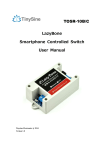
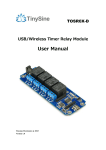
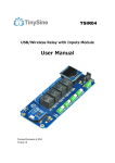
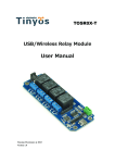
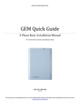
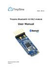
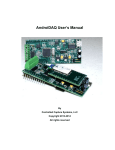
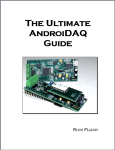
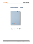
TOSR14x TOSR14x USB/Wireless Relay Module User Manual Tinysine Electronics @ 2015 Version 1.2 1 www.tinysine.com INTRODUCTION TOSR14x is an upgraded version of TOSR04. It supports password. It can be set to latching or momentary outputs. TOSR14x allows computer control switching of external devices by using the USB port of your computer. It also has a wireless extension port, can works with Xbee or BluetoothBee or WiFibee Module, So you can control your device via zigbee or Bluetooth or WiFi! The TOSR14x provides four volt free contact relay outputs with a current rating of up to 10Amp each. one DS18B20 temperature sensor port. The module is powered from a 5VDC power supply(or USB). The DC input jack is 2.1mm with positive core polarity, The relays are SPDT types. SPECIFICATIONS Rated voltage:DC 5V Power Mode:USB/DC 5V Baud rate:9600 Temperature input port Number of Relays:4 Relay switching power:10A 250VAC Latching or momentary outputs Password supported Communication Mode:USB/XBee/Bluetooth/WiFi IMPORTANT DISCLAIMER This device connects to the USB port of your computer and can be used to control external devices connected to its onboard relays. Incorrect wiring or shorts on the board can potentially cause damage to the controller itself,your computer's USB controller and/or your computer's motherboard if an external voltage make its way to the USB bus or the USB port is shorted. Extreme care must be taken when using this device to avoid any damage to your equipment. In particular,make sure you always disconnect the device from the USB port as well as any other power source when working on the device. TinySine Electronics,it's shareholder,employees,suppliers,distributors and/or resellers are not liable for any damage or loss of data as a result of the use of this device, including special,incidental,or consequential damages resulting from the use of this device,or under any legal theory,including lost profits,downtime,goodwill,damage to or replacement of 2 www.tinysine.com equipment or property,and any costs or recovering or reproducing any data stored in computers connected to this device. Your use of this circuit indicates your acceptance of these terms Module overview 1.Mini USB Port: this port is used to control TOSR14x by computer, or update board’s firmware. 2.Configuration Switch: set the switch to AP when configuring WiFi module with AP mode, and set the switch to Normal when use it.. 3 www.tinysine.com 3.Wireless Module Socket: plug wireless module to this socket if you want to control the board with wireless mode, compatible with XBee, BluetoothBee and WiFiBee. 4.DS18B20 Port: connect a DS18B20 sensor to get temperature and displays on your computer or phone. 5.Password Reset Button: considering we may forget board’s password, there is a convenient way to recover the board’s default password(123456). Power off the relay board and then long press the password reset button Power on the relay board LED “L”blinking a while and then stopped and keep lights on. Release the password reset button. Password reset success! 6.Relays: these 4 relays are SPDT types, each one can be turned ON/OFF independently. This kind of relay can stand high voltage up to 10A/250VAC. 7.Output Screw Terminals: these four screw terminals are used to connect electrical equipment, such as light bulbs, fans, heaters or anything you want to control with TOSR14x. You need to power equipment with extra power, but don’t exceed the voltage that relays can stand, and be careful! 8.DC Power In: connect a DC5V power to this port, then you can control this board in remote mode. 9.Power Jumper: choose a power source between USB and DC power. 4 www.tinysine.com Commands TOSR14x operates with an easy to use command set as described in the table below. How to use USB Control Mode: Notice: We need remove the wireless module in USB control mode Step1:Intall the Driver This module uses FT232RL USB to UART chip . Before using it you will need to download the FT232RL Driver. 5 www.tinysine.com Connect the module to computer and windows will detect it and ask for the drivers. Point windows to the inf folder and it will install the driver. A new com port will now appear. Step2: Run Realterm Serial Debug Tool to control TOSR14x The TOSR14x relay module is controlled using serial command. Here we use Realterm, but your favorite terminal should work fine. Be sure to set the communication speed to 9600 8-N-1. Connect the module to computer with USB cable, open the port and send test command you will see the relay on or off. If you want have a fast run, you can skip this step and jump to step 3. (1) Open Realterm, choose option “Port”, set the communication speed to 9600 8-N-1 and disable flow control then click “Open”, you should see the parameters from the bottom. 6 www.tinysine.com Port settings (2) In option “Display”, you can choose data format you want to display, Realterm has provided many selections such as ASCII, Hex, Dec, etc. Here we choose “Hex”. Set data format (3) Input the commands you want to send in option “Send”, but Realterm can only send data as Dec or Hex, here we choose Dec for demo. No matter which way you choose, the first thing before you can control TOSR14x is to verify the password! Input command “63, 64, 226, 01” and click “Send Numbers”, if you get response “01”, it means verification passed, and “00” means failed! 7 www.tinysine.com NOTE: 1. About how to verify password, please refer to command “63” as described in TOSR14x ’s commands list.. 2. In command “63, 64, 226, 01”, the last three numbers “64, 226, 01” stand for our default password “123456”. How come? Convert “123456” to hex, it’s “01 E2 40”, but we need to send the password conversely, that is “40 E2 01”, convert to dec is “64 226 01”. Verify password succeed (4) After verify the password successfully, you can send commands to control TOSR14x . For example, send command “100, 91” to turn on all the relays, and board will returns “0F” stands for relays’ state. 8 www.tinysine.com Turn all relays on and get relays’ state Step3: Testing Program To get the TOSR14x up and running in the minimum amount of time, we have put together an example program to demonstrate the functionality of TOSR14x. (1) Set power jumper to USB, open test program, choose board’s serial port, if the port is right, the program will reminds you to input the password. (2) Input the correct password then click “Verify”. 9 www.tinysine.com (3) After input the correct password, all the buttons become enabled, then you can control the board now! (4) If you want to change board’s password, just input the new one, and click “SET”. The password must be a 6 digit numbers 10 www.tinysine.com Latching Mode In latching mode, after you click relays buttons, relays are always in status of latched either ON or OFF, and if you click buttons again, relays will turned to the opposite status. Momentary Mode In momentary mode, relay’s contact always disconnected. You need to press and hold the button to keep relay closed, once remove from buttons, contact will disconnect automatically. 11 www.tinysine.com Wireless Control Mode: Bluetooth Remote Control The Tinysine Bluetooth Bee V2 module is a Bluetooth 4.0 smart ready wireless module that integrated both EDR and BLE, which means you can control board by Android and iOS. It based on CC2540 Bluetooth chipset which has a compact size and the pinout is compatible with XBee, suitable for all kinds of microcontroller systems that have 3.3 power out. The module comes with an onboard antenna which can provides better signal quality. It acts like a transparent serial port, which works with a variety of Bluetooth adapter and Bluetooth phones. 12 www.tinysine.com Controlled by computer 1. Connect with computer Recently, for most computers don’t support Bluetooth 4.0 perfectly, so we demonstrate using EDR mode. If your computer does not support bluetooth, you may need a bluetooth USB dongle like this: (1) Plug Bluetooth module to TOSR14x, make sure the configure switch is set to “Normal” position. Here we use remote control, so change the power jumper to DC power mode, then power the board by DC 5V power. 13 www.tinysine.com USB power to DC power mode (2) Plug bluetooth USB dongle to your computer, if you have installed the driver successfully, you should find a Bluetooth USB device from device manager. If your computer have equipped with Bluetooth, just ship this step. NOTE: If your Windows bluetooth drivers can’t use, you need to download BlueSoleil to use. (3) Open BlueSoleil, double click the middle button to turn on Bluetooth, then right click choose “Search Devices”. 14 www.tinysine.com (4) Our Bluetooth module usually comes with a mac address as “00:0E:0E:XX:XX:XX” in EDR mode, find such device and right click it, choose “Search Service”. (5) When finish search services, choose the option “Connect Bluetooth Serial Port”, then you may need to input the pair code 1234, if it’s your first time to connect with this Bluetooth module. 15 www.tinysine.com (6) Once your computer have connected with Bluetooth Bee V2, the “STATE” led stops blink. Meanwhile, the device turns green, and BlueSoleil shows “Connected”. (7) Now you can send commands to TOSR14x with Realterm, just like we did in USB mode, but don’t forget to change port number and verify the password at first! 16 www.tinysine.com Check Bluetooth Serial Port No. Change port No. 17 www.tinysine.com Send Dec command 100 → All relays on Controlled by smart phone We have a free application for you to control TOSR14x by smart phone, Android phone and iPhone are both available. 1. Connect with Android Phones (1) Download the Android application (Bluetooth Version) here and install it to your android phone. (2) Open your phone’s Bluetooth and the app. (3) Click menu key on your phone → Connect → Scan for devices. Your phone will search for the Bluetooth module automatically. Usually, our Bluetooth modules are named as “BT Bee-EDR”, but you can change it. 18 www.tinysine.com (4) Click BT Bee-EDR to connect, if it’s your first time to connect with the Bluetooth module, you may need to input the default pair code 1234. (5) After your phone has connected to TOSR14x, the interface will show “connected: BT Bee-EDR” at the top. Meanwhile, app will ask you for board’s password, only when you have input the correct password, you can control the board! NOTE: 19 www.tinysine.com If you have forgotten the password, you can press the reset button to recover the board. 2. Connect with iPhone (1) Download iPhone application (Bluetooth Version) here and install it to your iOS devices. (2) Open the app and click “Connect” or any button to detect nearby BLE devices. (3) When the app find a device named “BT Bee-BLE”, click this device to connect directly 20 www.tinysine.com because BLE devices don’t need the pair code. After TOSR14x has connected to iPhone, you will see the name from the top. Also, you need to input the correct password to access the board. 3. Control TOSR14x After your phone has connected to TOSR14x, you can control the board just as we control it in USB mode. (1) Slide “Momentary/Normal” button to choose the working mode. (2) “All On” and “All Off” button only works under Normal mode.. (3) If you connect a DS18B20 sensor to temperature input port, you will get the real-time temperature from the screen(NC means no ds18b20 connected). (4) Click “Setting” in menu, you can even change relay buttons’ name, maximum length is 6 characters. 21 www.tinysine.com WiFi Control Mode The Tinysine WiFiBee module is based upon Roving Networks' robust RN-171 Wi-Fi module and incorporates 802.11 b/g radio, 32 bit processor, TCP/IP stack, real-time clock, pre-loaded with Roving firmware to simplify integration and minimize development time of your application. In the simplest configuration, the hardware only requires four connections (PWR, TX, RX and GND) to create a wireless data connection. You need to configure the WiFi module according to your network before you can use it. Configure WiFiBee You can use the APP that we provided configure WiFibee. Both Android and iPhone are 22 www.tinysine.com works, you can download Android APP(WiFi Version) or iPhone APP(WiFi Version) and install it to you phone. (1) Set mode switch to “AP” position and then power the relay board. WiFibee LEDs should blink in sequence. (2) Open your smartphone’s WiFi. Refresh the wireless network until you can find a network named Wifly-EZX-XX, click it to connect. (3) Once connected, open the app and click the menu key to choose“Configure”(If you are using iPhone, you can find this option at the bottom). 23 www.tinysine.com (4) Input your network’s settings like SSID, password and IP address in turn, then click “Start”.The app will send commands to the WiFi module automatically. Click “Finish” when the app shows configuration is complete. (5) Disconnect TOSR14x from power and set the configuration switch back to the “Normal” position. (6) After configuration. Your WiFibee module should joined your wifi network. D1 slow Blink. 24 www.tinysine.com More WiFiBee setting method please visit: http://www.tinyosshop.com/index.php?route=information/news&news_id=26 Controlled by computer (1) Make sure the configuration switch is in “Normal” position and choose power mode as DC, here we use a DC 5V power. Here we use Realterm to send commands. (2) Open Realterm, set Port as “192.168.1.185:2000” then click Open, you will get response “2A48454C4C4F2A01”(ASCII is *HELLO*) which means you have connected to TOSR14x . (3) Now you can control TOSR14x , but you still need to verify password, only when you have input the correct password, you can control TOSR14x . 25 www.tinysine.com Send Dec command 100 → All relays on Controlled by smartphone You can also use WiFi to control TOSR14x, just like we control it using Bluetooth. Both android phones and iPhone works fine, here we can control TOSR by two methods. 1. Controlled via router (1) Connect your phone to the router, then open the app. (2) Choose “Connect device” and input WiFiBee’s IP address you have set before(default port is 2000 if you didn’t change it). (3) When your phone has connected with WiFi module, you need to verify the password (default password: 123456). 26 www.tinysine.com (4) Once you have input the correct password, app will give a prompt, then you can control TOSR14x! 2. Point to Point control (1) Set WiFiBee module mode switch to “AP” position, Turn on your phone’s WiFi to search for network created by WiFiBee module in AP mode(named as Wifly-EZX-XX). 27 www.tinysine.com (2) Join that network and then open the app. Connect: ->Give your relay board a name ->IP: 192.168.1.1 ->Port: 2000 192.168.1.1 is the default IP address in AP mode, not the IP you configured based on your wireless network. After your phone joined the network and verified the password, you can control TOSR as usual! APPENDIX 1. GL5A Relay Datasheet 2. RN171 WiFi Module Datasheet 3. WiFiBee Setting Guide 4. Realterm Serial Debug Tool 5. Test Program Contact us Address: Tinysine (Tinyos) Electronics 4-3 Hui Gu Park, Hai Tang Road, Hefei, Anhui, China Telephone: +86-551-65365921 Ext 801 Fax: +86-551-65365931 Working Time: 9:00-17:30 (GTM +8) Email: [email protected] 28