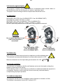
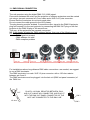
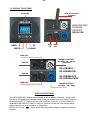
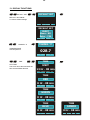
1
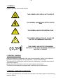
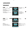
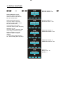
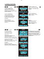
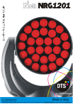
D.T.S. Illuminazione srl
Via Fagnano Selve 10/12/14
47843 Misano Adriatico (RN) ITALIA Tel +39 0541 611131 Fax +39 0541 611111
Made in Italy
[email protected] http://www.dts-lighting.it
2
Le informazioni contenute in questo documento sono state attentamente redatte e
controllate. Tuttavia non è assunta alcuna responsabilità per eventuali inesattezze.
Tutti i diritti sono riservati e questo documento non può essere copiato, fotocopiato,
riprodotto per intero o in parte senza previo consenso scritto della D.T.S .
D.T.S. si riserva il diritto di apportare senza preavviso cambiamenti e modifiche
estetiche , funzionali o di design a ciascun proprio prodotto. D.T.S non assume alcuna
responsabilità sull‟uso o sull‟applicazione dei prodotti o dei circuiti descritti.
The information contained in this publication has been carefully prepared and
checked. However, no responsibility will be taken for any errors. All rights are
reserved and this document cannot be copied, photocopied or reproduced, in part or
completely, without prior written consent from D.T.S.
D.T.S. reserves the right to make any aesthetic, functional or design modifications to
any of its products without prior notice. D.T.S. assumes no responsibility for the use or
application of the products or circuits described herein.
Les informations contenues dans le présent manuel ont été rédigées et contrôlées
avec le plus grand soin. Nous déclinons toutefois toute responsabilité en cas
d'éventuelles inexactitudes. Tous droits réservés. Ce document ne peut être copié,
photocopié ou reproduit, dans sa totalité ou partiellement, sans le consentement
préalable de D.T.S.
D.T.S. se réserve le droit d'apporter toutes modifications et améliorations esthétiques,
fonctionnelles ou de design, sans préavis, à chacun de ses produits. D.T.S. décline
toute responsabilité sur l'utilisation ou sur l'application des produits ou des circuits
décrits.
Las informaciones contenidas en este documento han sido cuidadosamente
redactadas y controladas. Con todo, no se asume ninguna responsabilidad por
eventuales inexactitudes. Todos los derechos han sido reservados y este documento
no puede ser copiado, fotocopiado o reproducido, total o parcialmente, sin previa
autorización escrita de D.T.S.
D.T.S. se reserva el derecho a aportar sin previo aviso cambios y modificaciones de
carácter estético, funcional o de diseño a cada producto suyo. D.T.S. no se asume
responsabilidad de ningún tipo sobre la utilización o sobre la aplicación de los
productos o de los circuitos descritos.
3
INDEX:
1- SYMBOLS
2- GENERAL WARNING
3- GENERAL WARRANTY CONDITION
4- TECHNICAL FEATURES
5- TECHNICAL SPECIFICATIONS
6- ACCESSORIES
7- IMPORTANT SAFETY INFORMATION
7.1 Fire prevention
7.2 Prevention of electric shock
7.3 Safety
7.4 Level of protection against the penetration of solid and liquid objects
8- VOLTAGE AND FREQUENCY
9- INSTALLATION
9.1 Safety cable
9.2 Protection against liquids
9.3 Movement
9.4 Risk of fire
9.5 Forced ventilation
9.6 Ambient temperature
10- MAINS CONNECTION
10.1 Protection
11- DMX SIGNAL CONNECTION
11.1 DMX Addresses
11.2 Selecting the DMX address
12- FIRMWARE UPDATING
13- DISPLAY FUNCTIONS
14- PERIODIC CLEANING
15- PERIODIC CONTROLS
16- DMX PROTOCOL
4
4
4
5
7
7
8
9
9
11
12
13
14
23
23
24
4
1- SYMBOLS
Graphic symbols used on this manual
THIS SYMBOL INDICATES A HOT SURFACE
THIS SYMBOL INDICATES ELECTRIC SHOCK
RISK
!
F
0,5M
THIS SYMBOL INDICATES GENERAL RISK
THIS SYMBOL MEANS “DO NOT PLACE THE
UNIT ON INFLAMMABLE SURFACES”
THIS SYMBOL INDICATES THE MINIMUM
DISTANCE TO BE KEPT BETWEEN THE DEVICE
AND THE LIT OBJECT
2- GENERAL WARNING
Read the instruction contained in this user manual carefully, as they give important
information regarding safety during installation , use and maintenance.
The device is not for domestic use and must be installed by a qualified electrician or
experienced person.
Always disconnect the device from the mains before maintenance.
The device must always be equipped with an efficient ground connection.
3- GENERAL WARRANTY CONDITIONS
The unit is guaranteed for 36 months from the date of purchase against manufacturing
material defects.
5
4- TECHNICAL FEATURES
Overview
NICK NRG 1201 is the most efficient LED moving head wash light ever produced and,
thanks to its specifically developed optical group, fears no competition.
The exceptional brightness/consumption ratio makes NICK NRG 1201 a truly “green”
fixture.
NICK NRG‟s new-generation optical group is an exclusive D.T.S. feature.
NICK NRG 1201 is equipped with 30 high-power full-colour LEDs (RGBW).
NICK NRG 1201 features 8°- 50° motorized zoom with a high efficiency optical system
enabling it to be used as a PC Beam or a very wide Wash and ultra-fast silent Pan/Tilt.
NICK NRG 1201 (Cod. 03.LDR006.FFP; Cod. 03.LDR006.FWFP), is also equipped
with the “FPR” system (patent pending), which enables limitless pan rotation in both
directions, with no need for inversion.
Applications
NICK NRG 1201 is suitable for top professional applications, such as tours and special
events.
NICK NRG 1201 is also available as NICK NRG 1201 CT (30 Full White LEDs,
2700°K-6500°K).
Product codes
03.LDR006.F
03.LDR006.FFP
NICK NRG 1201 FULLCOLOR BLACK ZOOM
NICK NRG 1201 FULLCOLOR FPR BLACK ZOOM
03.LDR006.FW
NICK NRG 1201 CT FULLWHITE BLACK ZOOM
03.LDR006.FWFP NICK NRG 1201 CT FULLWHITE FPR BLACK ZOOM
LED Technology
* 30 Full Colour LEDs (RGBW)
Optical group
* 8°- 50° linear motorized zoom with high-efficiency optical system
* Uniform projection on surfaces, from very wide Wash to PC Beam
Colour generation
* 16 million colours
* Wide palette of pure uniform whites with variable
linear colour temperature (2700°K – 8000°K)
Interface / Control / Programming
* Multi-function OLED graphic colour display + 4 soft keys:
control / management / monitoring of the main parameters
* Controlled via DMX 512 and RDM standard digital communication protocols
* Wireless ready
* Ethernet ready
* Internal operating system updatable via D.T.S. RED BOX interface via “D.T.S.
firmware upgrade utility” program on windows based PC
6
DMX
20 DMX channels
Pan & Tilt
NICK NRG 1201 FPR (Cod. 03.LDR006.FFP; Cod. 03.LDR006.FWFP)
* „FPR‟: limitless pan rotation, in either direction, never having to reverse motion
Tilt 270° (1,2 sec.)
NICK NRG 1201 (Cod. 03.LDR006.F; Cod. 03.LDR006.FW)
* Ultra-fast movement: Pan 540° (2 sec.); Tilt 270° (1,2 sec.)
* 16-bit movement resolution
* 4 Selectable speed ranges
Power supply
* Electronic full-range AC 90-260 V 50 / 60 Hz
* Power consumption: 90 V – 3,7 A – 340 W ; 120 V – 2,83 A – 340 W ;
230 V – 1,47 A - 340 W ; 260 V – 1,3 A – 340 W
Connectors
* DMX: 4 XLR connectors (3-pole In and Out; 5-pole In and Out) by Neutrik;
* Power supply: POWERCONN In/Out connectors by Neutrik.
Operating ambient temperature
-10° / 40°
Weight
10,5 Kg
International certifications
Certification CE; LED Class: Class 2 LED product
7
5- TECHNICAL SPECIFICATIONS
Dimensions
Packaging Dimensions (LxWxH)
530 x 430 x 414 mm
Weight: 13 Kg
306 mm
218 mm
413 mm
369x218x497 mm
195 mm
497 mm
Unit Dimensions (LxWxH)
369 mm
Weight: 10,5 Kg
6- ACCESSORIES
As standard
• 1 x POWERCONN male cable connector (cod. 0520P014)
• 1 x XLR 5 Pins male cable connector (cod. 0508B028)
• 1 x XLR 5 Pins female cable connector (cod. 0508B027)
• “C” Clamp GQUICK with “Fast Lock” connection 1/4 turn (cod. 0521A014)
• User‟s manual
Optional (on request)
Flight case
• Professional Flight case for 4 units; compartment for accessories, swivel wheels,
cover with hinges with-stay, dishes on cover for piling, 8 handles (2 eachside) (cod.
0521C051.1)
Wireless DMX receiver retrofit
• Wireless DMX Receiver Card with INDOOR IP20 omni. 2dBi antenna included
(cod.03.LA.126)
Clamps / safety wires
• “C” Clamp G60 black (max. load 50Kg) (cod. 0521A004)
• “C” Clamp G60 chrome (max. load. 50Kg) (cod. 0521A004.20)
• “C” Clamp GQUICK with “Fast Lock” connection 1/4 turn (max. load. 80Kg) (cod.
0521A014)
• “C” Clamp G100 black / professional (max. load. 200Kg) (cod. 0521A015)
• Omega clamp with “Fast Lock” connection 1⁄4 turn 1 couple (2 pieces) (Cod.
02K00467)
• Safety wire (3mm x 60 cm), ring spring catch, max. capacity load 60Kg (cod.
0521A010)
8
7- IMPORTANT SAFETY INFORMATION
7.1 Fire prevention:
-Never locate the fixture on any flammable surface.
-Minimum distance from flammable materials: 1 MT. F
-Minimum distance from the closest illuminable surface: 0,5 MT. 0,5M
-Replace any blown or damaged fuses only with those of identical value.
Refer to the wiring diagram if there is any doubt.
-Connect the projector to mains power via a thermal magnetic circuit breaker.
7.2 Prevention of electric shock:
-High voltage is present inside the unit. Unplug the unit prior to performing any
function which involves touching the inside of the moving head.
-The level of technology inherent in the NICK NRG 1201 requires the assistance of
specialised personnel for all servicing.
Please refer to an authorised D.T.S. service centre.
-A good earth connection is essential for proper functioning of the projector.
-Never connect the unit without proper earth connection.
-The fixture should be located in places with a good air ventilation.
7.3 Safety:
!
-The projector should always be installed with bolts, clamps and other tools that are
capable of supporting the weight of the unit.
-Always use a second safety cable to sustain the weight of the unit in case of the
failure of the main fixing point.
-The external surface of the unit, at various points, may exceed 70°C. Never handle
the unit until at least 10 minutes have elapsed since the projector was turned off.
-Never install the fixture in an enclosed area lacking sufficient air flow.
The ambient temperature should not exceed 40°C.
7.4 Level of protection against the penetration of solid and liquid objects:
!
-The projector is classified as an ordinary appliance and its protection level against the
penetration of solid and liquid objects is IP 20.
9
8- VOLTAGE AND FREQUENCY
The NICK NRG 1201 can operate at 90-260 VOLT 50 or 60 Hz.
9- INSTALLATION
NICK NRG 1201 may be either floor or ceiling mounted.
For floor mounting installations, the NICK NRG 1201 is supplied with four rubber
mounting feet on the base.
For ceiling mounted installations, we reccomend the use of appropriate clamps to fix
the unit to the mounting surface.
The supporting structure from which the unit is hung should be capable of bearing the
weight of the unit, as should any clamps used to hung it. The structure should also be
sufficiently rigid so as not to move or shake whilst the NICK NRG 1201 is moving.
Four 1/4 turn Fast Locks connections placed in the base of the unit allow to hang the
NICK NRG 1201 by using the Fast Lock “C” clamps provided in the box.
9.1- Safety cable
!
We recommend the use of a safety cable or chain connected to the NICK NRG 1201
and to the suspension truss in order to avoid the fixture accidentally falling should the
main fixing point fail.
Make sure that the iron cable or chain can bear the weight of the entire unit.
You may attach the safety chain/cord to the attachment point (A) located on the base
of the fixture, as shown in the picture below.
SAFETY CHAIN/CORD
ATTACHMENT POINT
A
10
!
9.2 Protection against liquids
The projector contains electric and electronic components which should under no
circumstances come into contact with oil, water or any other liquid.
The proper unit functioning would be compromised should this occur.
9.3- Movement
NICK NRG 1201 FPR (Cod. 03.LDR006.FFP; Cod. 03.LDR006.FWFP)
Unlimited Pan rotation; Tilt 270° (1,2 sec.)
NICK NRG 1201 (Cod. 03.LDR006.F; Cod. 03.LDR006.FW)
Ultra-fast movement: Pan 540° (2,0 sec.); Tilt 270° (1,2 sec.)
DO NOT place any obstructions in the path of the projector's movement.
270°
270°
!
WARNING
Do not place any object in the
path of the projector‟s
movement
Free Pan Rotation („FPR‟)
(Cod. 03.LDR006.FFP)
(Cod. 03.LDR006.FWFP)
540°
No „FPR‟
(Cod. 03.LDR006.F)
(Cod. 03.LDR006.FW)
9.4- Risk of fire
Each fixture produces heat and must be installed in a well-ventilated place.
The minimum recommended distance from flammable material is 1 MT.
Minimum distance from the object being illuminated is 0,5 MT.
F
0,5M
9.5- Forced ventilation
You will note, on inspection, that the unit features various air inlets and cooling fans
located on the head of the fixture.
These should, under no circumstances, be blocked or obstructed whilst the projector is
in operation. Doing so could cause the fixture to seriously overheat thereby
compromising its proper operation.
9.6- Ambient temperature
The projector should never be installed in places that lack a constant air flow.
The ambient temperature should NOT exceed 40°C.
11
10- MAINS CONNECTION
NICK NRG 1201 operate at 90-260 VOLT 50-60 Hz.
Prior to connecting the unit to your mains supply, ensure that the model in your
possession correctly matches the mains supply available.
For connection purposes, ensure that your plug is capable of supporting 1,5 amps
at 230V, or 3 amps at 90 V.
Strict adherence to regulatory norms is strongly recommended.
MAINS AC OUTPUT 90 – 260 V 50 / 60 Hz (16A Max)
MAX 10 NICK NRG 1201 UNITS @ 230V
MAX 5 NICK NRG 1201 UNITS @ 120V
Cod. 03.LDR006.F
Cod. 03.LDR006.FW
Cod. 03.LDR006.FFP
Cod. 03.LDR006.FWFP
MAINS AC INPUT 90 – 260 V 50 / 60 Hz
Wireless DMX Receiver Retrofit (Cod. 03.LA.126)
FUSE 5A T 5X20
10.1- Protection
!
The use of a thermal magnetic circuit breaker is recommended for each NICK NRG
1201.
12
11- DMX SIGNAL CONNECTION
The unit operates using the digital DMX 512 (1990) signal.
Connection between the mixer and the projector or between projectors must be carried
out using a two pair screened ø 0.5 mm cable and a XLR 5 or 3 pins connector.
Ensure that the conductors do not touch each other.
Do not connect the cable ground to the XLR chassy.
The plug housing must be isolated. Connect the mixer signal to the DMX IN projector
plug and connect it to the next projector by connecting the DMX OUT plug on the first
projector to the DMX IN plug of the second one.
This way, all the projectors are cascade connected.
NB. If the display showing the DMX address flashes, then one of the following errors
has occurred:
- DMX signal not present
- DMX address not valid
- DMX reception problem
CONTROLLER
S TA N D A R D
DMX 512
5
1
4
2
1=GND
2=DATA3=DATA+
3
DMX OUT
DMX IN
DMX OUT
DMX IN
DMX OUT
DMX IN
DMX OUT DMX IN
DMX OUT
For Installations where long distance DMX cable connections are needed, we suggest
to use a DMX terminator.
The DMX terminator is a male XLR 3-5 pins connector with a 120 ohm resistor
between pin 2 and 3.
The DMX terminator must be plugged into the last unit (DMX out panel connector) of
the DMX line.
5
1
4
2
3
120 ohm
OUT
PLACE A 120 OHM RESISTOR BETWEEN PIN 2
AND 3 OF A MALE XRL CONNECTOR AND PLUG IT
INTO THE DMX OUT PANEL CONNECTOR OF THE
LAST UNIT CONNECTED TO THE DMX LINE
PIN 3
PIN 2
13
11.1-DMX Addresses
NICK NRG 1201 can be controlled with 20 DMX channels.
In order to use the unit in 20 channels, set the following addresses on the mixer:
Projector 1
Projector 2
Projector 3
…..
projector 6
A001
A021
A041
A….
A101
If you want to select the next projector, just add “20”
11.2-Selecting the DMX address
1) Press the UP-DOWN key until you reach the required DMX channel. The numbers
on the display will start to flash (but the new DMX address hasn't yet been set).
2) Press ENTER to confirm your selection. The numbers on the display will stop
flashing and the projector is now setted to the new DMX address.
TRICKS:
if you keep pushed the UP or DOWN keys, the channels are calculated more quickly
and you get a faster selection.
12- FIRMWARE UPDATING
Warning:
This procedure require a base knowledge of computer applications and Windows
Hyperterminal program. Please refer to an authorised D.T.S. service centre.
!
To update the software version of the NICK NRG 1201 you need:
D.T.S. RED BOX interface (D.T.S. Code: 03.LA.008).
USB-DMX Driver for the D.T.S. RED BOX interface.
D.T.S. Firmware upgrade utility program.
(The driver and the installation procedure are available in our web site
www.dts-lighting.it)
Updating the software version.
Please follow the procedure below to perform the update:
1. Install the D.T.S. RED BOX USB-DMX driver on the PC you will use to update the
unit software.
2. Connect the D.T.S. RED BOX interface to the PC by using a USB cable.
3. Connect the D.T.S. RED BOX interface to the fixture by using a DMX cable.
4. Download the new software version into the unit by using D.T.S. Firmware upgrade
utility program.
14
13- DISPLAY FUNCTIONS
2dBi IP20 omnid.
antenna
DISPLAY
WIRELESS DMX
RECEIVER
RETROFIT
03.LA.126
UP
DOWN
MENU
ENTER
DMX
IN
DMX
OUT
DMX OUT
MAINS AC OUTPUT
90-260V 50 / 60 Hz
(16A Max)
DMX IN
03.LDR006.F
03.LDR006.FW
DMX IN
03.LDR006.FFP
03.LDR006.FWFP
DMX OUT
MAINS AC INPUT
90-260V 50 / 60Hz
DISPLAY FUNCTIONS
The NICK NRG 1201 display panel shows all the available functions . Using these
functions, it is possible to change some of the parameters and add some functions.
Changing the D.T.S. setting can vary the functions of the unit so that it does not
respond to the DMX 512 used to control it. Carefully follow the instructions below
before carrying out any variations or selections.
NOTE: the symbol
shows which key has to be pushed to obtain the desired
function.
15
13- DISPLAY FUNCTIONS
Software version 1.04
Menu
Up-Down
Display
ENTER
Up-Down
DISPLAY
POSITION
DISPLAY POSITION / STAND BY
Display Position:
Reverses display's reading depending on
the mounting position
(on the ground or suspended).
Display Standby:
To turn off the display (after 5 seconds)
or leave it always on.
Up-Down
DMX Set
ENTER
Up-Down
DMX MODE / MACRO
DMX Mode
20 channels
MENU ENTER DOWN
UP
DISPLAY
Display Standby
OFF = Display Standby
disabled (Default)
ON = Display goes OFF
after 5 seconds
STANDBY
OFF
ENTER
UP
DMX SET
DMX Mode
20 channels
DMX MODE
ENTER
20With
chFAR
20 ch
MENU ENTER DOWN
MACRO
Macro Mode:
STD = Standard (Default)
EXT = Extended; enable rainbow
effects on Macro channel (DMX ch 16)
ENTER
AA
MENU ENTER DOWN
Menu
Display Position
ON THE GROUND (Default)
SUSPENDED
UP
DMX SET
DMX
MACRO
MODE
20
STD
ch
MENU ENTER DOWN
UP
MACRO
STD = Standard mode enabled
(Default)
EXT = Extended; enable rainbow
effects on Macro channel
(DMX ch 16)
16
13- DISPLAY FUNCTIONS
Menu
Up-Down
LED
ENTER
Up-Down
DMX
LED
SET
RED Min default = 0
RED Max default = 100
DMX
REDMODE
MIN
RGBA MINIMUM VALUES
This menu allow to select the
minimum levels for Red, Green,
Blue and Amber/White
RGBA MAXIMUM VALUES
This menu allow to select the
maximum levels for Red, Green,
Blue and Amber/White
These settings have priority
on Master Dimmer (DMX channel 9)
200ch
MENU ENTER DOWN
DMX
LED
SET
GREEN
DMX MODE
MIN
BLUE Min default = 0
BLUE Max default = 100
200ch
MENU ENTER DOWN
SMOOTH VALUE
This menu allow to select the value
of the delay (in milliseconds) for
RGBA and Dimmer channels
reaction to DMX or Program
variation.
4 = 25 ms delay (Fast response)
20 = 250 ms delay (Slow response)
UP
UP
DMX
LED
SET
GREEN Min default = 0
GREEN Max default = 100
DMX
BLUEMODE
MIN
200ch
MENU ENTER DOWN
UP
DMX
LED
SET
AMBER
DMX MODE
MIN
AMBER Min default = 0
AMBER Max default = 100
200ch
MENU ENTER DOWN
UP
DMX
LED
SET
SMOOTH
Range = Off – 20
Default = 4
DMX
SMOOTH
MODE
204ch
MENU ENTER DOWN
UP
ENTER
17
13- DISPLAY FUNCTIONS
Menu
Up-Down
LED
ENTER
Up-Down
GAMMA CORRECTION
This menu allow to select
between Linear current output
or Quadratic current output for LEDs
Default = Quadratic
DMX
LED
SET
GAMMA
DMX MODE
CORR.
QUAD
20 ch
MENU ENTER DOWN
OUTPUT
DMX MODE
FREQ.
20
610
ch
MENU ENTER DOWN
Menu
Up-Down
AUTO
ENTER
BOOST
With BOOST active, the
LED‟s current is set to
500 mA (30% more gain)
Default = Enabled
DMX
BOOST
MODE
20
ON
ch
MENU ENTER DOWN
Up-Down
AUTOMATIC MODE
Automatic demo game
without DMX controller
STEP 01/16
Chase with 16 steps previously
created in REC MODE
Speed time, Wait time, Dimmer, Pan,
Tilt and Zoom values selectable by user.
PERSONAL COLOURS
RGBA, Dimmer, Shutter, Pan, Tilt and
Zoom values selectable by user.
ENTER
SURE?
DMX
MODE
Menu - NO
Enter - YES
20 ch
UP
AUTO-PROGRAM
DMX SET
DMX
STEP
MODE
01/16
20 ch
MENU ENTER DOWN
RAINBOW
Rainbow colours effect.
Speed time, Dimmer, Shutter, Pan,
Tilt and Zoom values selectable by user.
UP
DMX
AUTO
SET
MENU ENTER DOWN
UP
AUTO-PERS.COL.
DMX SET
DMX
RED
MODE
20
120
ch
MENU ENTER DOWN
UP
AUTO-RAINBOW
DMX SET
DMX
SPEE
MODE
20
0010
ch
MENU ENTER DOWN
OUTPUT FREQUENCY
Range = 610 Hz – 10 KHz
Default = 610 Hz
UP
DMX
LED
SET
BOOST DRIVING
This menu allow to increase
the LED‟s current from 350 mA
to 500 mA
ENTER
UP
DMX
LED
SET
OUTPUT FREQUENCY
This menu allow to adjust
the PWM frequency value (Hz)
in order to reduce flickering in
the process of your camera
recordings
GAMMA CORRECTION
Linear = Linear current output
Quadratic = Linear light output
(default)
UP
By setting all the units connected
to the MASTER, to DMX address 1,
them will be synchronized with the
Master unit following the chase
selected on it, including TIME, WAIT,
Pan&Tilt and Zoom position of the
MASTER unit.
18
13- DISPLAY FUNCTIONS
FIXED COLOURS
Sixteen Colour Macros as
on “MACRO” channel.
Dimmer, Shutter, Pan, Tilt and
Zoom values selectable by user.
AUTO-FIXED
DMX SETCOL.
WHITE MACROS
Sixteen macros for White
color (from 2700 ° K to 8000 ° K
for NICK NRG 1201; from
2700 ° K to 6500 ° K for NICK
NRG 1201 CT).
Dimmer, Shutter, Pan, Tilt and
Zoom values selectable by user.
MENU ENTER DOWN
DMX
COLOR
MODE
201ch
UP
Up-Down
SLAVE
ENTER
Up-Down
SLAVE MODE SETTING
This menu allow to set the
NICK NRG 1201 as slave unit.
DMX signal must be present
from MASTER unit (set in
AUTO MODE) in order to ran
the units in SLAVE mode.
By setting all the SLAVE units
connected to the MASTER, to
DMX addess 1, them will be
synchronized with the Master
unit following the chase
selected on it, but running their
own Pan&Tilt and Zoom position.
ENTER
AUTO-WHITE
DMX SET
DMX MODE
WHITE
NO.
201ch
UP
MENU ENTER DOWN
Menu
By setting all the units connected
to the MASTER, to DMX address 1,
them will be synchronized with the
Master unit following the chase
selected on it, including TIME, WAIT,
Pan&Tilt and Zoom position of the
MASTER unit.
DMX
SLAVE
SET
SURE?
DMX
MODE
Menu - NO
Enter - YES
20 ch
UP
MENU ENTER DOWN
SLAVE
DMX
SET
DMX
PAN
MODE
20
128
ch
MENU ENTER DOWN
UP
SLAVE
DMX
SET
DMX
TILT
MODE
20
128
ch
UP
MENU ENTER DOWN
SLAVE
DMX
SET
DMX
ZOOM
MODE
200ch
MENU ENTER DOWN
UP
The SLAVE unit receive DMX
signal from the MASTER unit.
By setting all the SLAVE units
connected to the MASTER, to
DMX address 1, them will be
synchronized with the Master
unit following the chase selected
on it, but running their own
Pan&Tilt and Zoom position.
ENTER
19
13- DISPLAY FUNCTIONS
Menu
Up-Down
WIRELESS
ENTER
Up-Down
WIRELESS
DMX SET
SELECTION
DMX MODE
WIRELESS DMX
Wieless DMX enabled / disabled.
By activating WDMX MODE, it will
be possible to control NICK NRG
1201 via D.T.S. ANTENNA Wireless
DMX Transmitter (cod. 03.E1271).
Wireless DMX Receiver Kit
(Cod. 03.LA.126) on NICK NRG
1201 is available on request.
WIRELESS DMX SYSTEM
DISABLED (Default)
ENTER
WIRELESS DMX SYSTEM
ENABLED
ENTER
20
OFF
ch
MENU ENTER DOWN
UP
WIRELESS
DMX SET
SELECTION
DMX MODE
20
ON
ch
MENU ENTER DOWN
UP
WIRELESS
DMX SET
UNLINK
20 ch
DMX MODE
MENU ENTER DOWN
UNLINK = LOG OUT
ENTER
UP
Logging on NICK NRG 1201 (WIRELESS DMX must be enabled on the unit).
To log on the NICK NRG 1201 in the WIRELESS system simply press and quickly release the function
button on the transmitter .
The transmitter will start flashing rapidly red/green scanning for new free receivers / NICK NRG 1201
units. When a NICK NRG 1201 logs on to the transmitter the LINK green light on transmitter starts to
flash rapidly.
After approximately 10 seconds the transmitter will jump back to normal mode and continue transmitting
data. The NICK NRG 1201 now try to synchronize to the transmitter.
When synchronized to the transmitter, 2 different modes are possible:
1. Antenna transmitter has detected and transmits a DMX signal, in this mode a solid green light is seen
on the transmitter and solid display is seen on NICK NRG 1201.
2. No DMX signal connected, the Antenna transmitter will flash red/green; display blinking on NICK
NRG 1201.
To log off NICK NRG 1201 from a transmitter simply select UNLINK function under WIRELESS DMX
MENU and press ENTER.
When NICK NRG 1201 is logged off the display is blinking, meaning its available for log in on a new
transmitter.
Logging out a NICK NRG 1201.
Select UNLINK function under WIRELESS DMX MENU and press ENTER.
When NICK NRG 1201 is logged off the display is blinking, meaning its available for log in on a new
transmitter.
Logging out all NICK NRG 1201 linked to a transmitter.
Press and hold the function button of the transmitter for about 3 seconds. When the display is blinking
on NICK NRG 1201, it mean that the units are logged out.
Transmitter, Status LED.
Flashing red/green, no dmx connected.
Solid green, dmx signal detected and transmitted.
Fast flashing red/green, log in mode (every free NICK NRG 1201 unit, not logged in to any other
transmitter, will be logged on)
NICK NRG 1201 Status.
Display blinking, not logged on to a transmitter (free).
Solid display, logged on to a transmitter and receiving dmx data.
20
13- DISPLAY FUNCTIONS
Menu
Up-Down
EMERGENCY
ENTER
Up-Down
EMERGENCY
DMX SET
SELECTION
DMX MODE
EMERGENCY
Emergency operating mode.
By setting Emergency mode, it will
be possible to select one of the
16 preprogrammed WHITE cues
that will then ran if DMX signal is
missing or not available.
Useful for Emergency EXIT
illumination on public areas.
Dimmer level, Pan&Tilt and
Zoom values selectable by user.
EMERGENCY
Disabled = Default
20
OFF
ch
MENU ENTER DOWN
UP
EMERGENCY
DMX SET
SELECTION
DMX MODE
EMERGENCY
Enabled
20
ON
ch
MENU ENTER DOWN
UP
EMERGENCY
DMX SET
DMX
WHITE
MODE
WHITE (1-16)
Default = WHITE 1
201ch
MENU ENTER DOWN
UP
EMERGENCY
DMX SET
DMX
DIMMER
MODE
DIMMER
Default = 255
20
255
ch
MENU ENTER DOWN
UP
EMERGENCY
DMX SET
PAN
Default = 128
DMX
PAN
MODE
20
128
ch
MENU ENTER DOWN
UP
EMERGENCY
DMX SET
DMX
TILT
MODE
TILT
Default = 128
20
128
ch
UP
MENU ENTER DOWN
EMERGENCY
DMX SET
DMX
ZOOM
MODE
200ch
MENU ENTER DOWN
UP
ZOOM
Default = 0
ENTER
21
13- DISPLAY FUNCTIONS
Menu
Up-Down
DEFAULT SET
ENTER
Up-Down
DEFAULT
DMX SET
SET
ENTER
DMX MODE
DEFAULT SETTINGS
To restore default settings
20 ch
UP
MENU ENTER DOWN
DEFAULT
DMX SET
SET
DMX
SURE?
MODE
Menu - NO
Enter - YES
20 ch
UP
MENU ENTER DOWN
Menu
Up-Down
TEMPER. °C
ENTER
TEMPER.
DMX SET°C
DMX MODE
TEMPERATURE
Unit temperature
028.7
20 ch
MENU ENTER DOWN
Menu
Up-Down
TIME
ENTER
Up-Down
LIFE TIME
This menu show the total UNIT life
time and the RGBA life time
UP
DMX
TIME
SET
ENTER
DMX
MODE
UNIT
20- 08
chmin
13 Hr
MENU ENTER DOWN
UP
DMX
TIME
SET
DMX
MODE
RED
20- 08
chmin
0 Hr
MENU ENTER DOWN
UP
DMX
TIME
SET
DMX
MODE
GREEN
20- 08
chmin
0 Hr
MENU ENTER DOWN
UP
DMX
TIME
SET
DMX
TIME
SET
DMX
MODE
BLUE
DMX
MODE
AMBER
20- 08
chmin
0 Hr
MENU ENTER DOWN
UP
20- 08
chmin
0 Hr
MENU ENTER DOWN
UP
22
13- DISPLAY FUNCTIONS
Menu
Up-Down
SYSTEM
ENTER
Up-Down
PAN INVERSION / TILT INVERSION /
PAN SPEED / TILT SPEED /
ZOOM SPEED / FAN MAX SPEED /
RESET BY DMX / MOTORS
FIRMWARE UPGRADE.
DMX
SYSTEM
SET
PAN
DMX
INVERSION
MODE
20
ch
NORM
MENU ENTER DOWN
DMX
SYSTEM
SET
TILT
DMX
INVERSION
MODE
TILT INVERTION
This menu allows to set the Tilt
movement. Normal or Reversed.
MENU ENTER DOWN
TILT SPEED
Tilt Speed control (1-8)
ZOOM SPEED
Zoom Speed control (1-4)
FAN MAX SPEED
This menu‟ allow to select the
internal fans speed.
20
ch
NORM
MOTORS FIRMWARE UPGRADE
This menu‟ allow to upgrade the
firmware for ZOOM and Pan&Tilt
circuit boards.
TILT INVERSION
Default = NORM
UP
DMX
SYSTEM
SET
PAN
DMX SPEED
MODE
204ch
MENU ENTER DOWN
PAN SPEED CONTROL
Default = 4
UP
DMX
SYSTEM
SET
TILT
DMX SPEED
MODE
TILT SPEED CONTROL
Default = 4
4
MENU ENTER DOWN
RESET BY DMX
This menu‟ allow to enable /
disable the Motors reset control
(Pan&Tilt and Zoom) via DMX.
ENTER
UP
PAN INVERSION
This menu allows to set the Pan
movement. Normal or Reversed.
PAN SPEED
Pan Speed control (1-8)
PAN INVERSION
Default = NORM
UP
DMX
SYSTEM
SET
ZOOM
DMX MODE
SPEED
ZOOM SPEED CONTROL
Default = 1
201ch
MENU ENTER DOWN
UP
DMX
SYSTEM
SET
FAN
DMX
MAX
MODE
SPEED
20
ch
100%
MENU ENTER DOWN
UP
DMX
SYSTEM
SET
RESET
DMX BY
MODE
DMX
20
ch
ENAB
MENU ENTER DOWN
RESET BY DMX
Enable: Motors reset enabled via DMX
(Default)
Disabled: Motors reset disabled via DMX
Now: Instant motors reset.
UP
DMX
SYSTEM
SET
DMX
MOTORS
MODE
FW UPGRADE
20 ch
MENU ENTER DOWN
FAN MAX SPEED
50% - 100%
Default = 100%
UP
MOTORS FIRMWARE UPGRADE
Zoom and Pan&Tilt circuit boards
firmware upgrade.
23
13- DISPLAY FUNCTIONS
Menu
Up-Down
SOFTWARE
ENTER
Up-Down
SOFTWARE
LEDs circuit board software,
MOTORS circuit boards software
(Pan&Tilt - Zoom)
SOFTWARE
DMX SET
DMXLED
MODE
LEDs CIRCUIT BOARD
SOFTWARE
ENTER
20 ch
Id 0D1307C1
v1.04 Jan 23 2012
MENU ENTER DOWN
UP
SOFTWARE
DMX SET
DMX
Motors
MODE
20 ch
MOTORS CIRCUIT BOARDS
SOFTWARE
PAN&TILT - ZOOM
Pan/Tilt v.18
Zoom v.14
MENU ENTER DOWN
UP
14- PERIODIC CLEANING
Front lenses Glass
The dust can reduce the luminous output substantially.
Regularly clean the front lenses glass using a soft cotton cloth, dampened with a
specialist glasses cleaning solution.
Fans and air passages
The fans and air passages must be cleaned approximately every 6 weeks.
This periodic cleaning will depend of course, on the conditions in which the projector is
operating.
Suitable instruments for performing this type of maintenance are a brush and a
common vacuum cleaner or an air compressor.
If necessary, clean the fans and air passages more frequently.
15- PERIODIC CONTROLS
!
Mechanical parts
Periodically check all mechanical parts and the gaskets, replacing them if necessary.
Electrical components
Check all electrical components for correct earthing and proper
attachment of all connectors, refastening if necessary.
Attention: Disconnect mains power prior to removing the
projector housing.
Fuse replacement
Locate the fuse, which protect the electronics, in the base of the
NICK NRG 1201. Using a multimeter, test the condition of the fuse,
replacing it with one of equivalent type if necessary.
Attention: Disconnect mains power prior to removing the
projector housing.
24
16- DMX PROTOCOL
20 CHANNELS MODE
1
2
3
4
5
6
7
8
9
10
11
12
13
14
15
16
17
18
19
20
PAN msb 540°
PAN Isb
TILT msb 270°
TILT Isb
SPEED MOVEMENT
PAN FPR (Active only on units with FPR: 03.LDR006.FFP; 03.LDR006.FWFP)
NO FUNCTION
SHUTTER
DIMMER
RED
GREEN
BLUE
WHITE
WHITE PREPROGRAMMED
CTC
MACRO
FUNCTION (Recall, Create and Store the Custom white)
ZOOM
NO FUNCTION
RESET
DMX CHANNEL
1
Parameter: PAN msb
DMX CHANNEL
2
Parameter: PAN lsb
DMX CHANNEL
3
Parameter: TILT msb
DMX CHANNEL
4
Parameter: TILT lsb
DMX CHANNEL
5
Parameter: SPEED MOVEMENT
DMX range
Value
000-010
011-025
026-127
128-247
248-255
Mid Point DMX
value
Move Range
(degrees)
Mode
Option
Function
Standard
Fast movement
Vector mode
from fast to
slow
Variable time
reaction to
DMX signal (fast
to slow)
Slow reaction
time to DMX
signal
25
DMX CHANNEL
6
DMX range
Value
Mid Point
DMX
value
Parameter: PAN FPR (Active only on units with FPR: 03.LDR006.FFP; 03.LDR006.FWFP)
Move Range
(degrees)
Mode
000-010
011-020
021-030
031-040
041-050
051-060
061-070
071-080
081-090
091-100
101-110
111-120
121-182
Position mode 540° (standard path)
Position mode 360° (1 turn)
Position mode 720° (2 turns)
Position mode 1080° (3 turns)
Position mode 1440° (4 turns)
Position mode 1800° (5 turns)
Position mode 2160° (6 turns)
Position mode 2520° (7 turns)
Position mode 2880° (8 turns)
Position mode 3240° (9 turns)
Position mode 3600° (10 turns)
Position mode 360° smart path
Forward spin rotation speed from
max to min
Stop
Reverse spin rotation speed from
min to max
183-193
194-255
DMX CHANNEL
7
DMX range
Value
Mid Point
DMX
value
Parameter: NO FUNCTION
Move Range
(degrees)
Mode
Option
000-255
8
DMX range
Value
Mid Point
DMX
value
Parameter: SHUTTER
Move Range
(degrees)
Mode
Function
Option
000-009
010-019
020-029
030-119
120-149
150-179
Black-out
Open
Black-out
Strobe (from 3.27 s to 30 ms)
Pulse up (from 42.6 s to 120 ms)
Pulse down (from 42.6 s to 120 ms)
Random strobe (Dimmer, Red,
Green, Blue, Amber channels
active)
Full independent Random Strobe
(Dimmer, Red, Green, Blue, Amber
channels disabled)
Open
180-204
205-229
230-255
DMX range
Value
000-007
008-255
Function
NO FUNCTION
DMX CHANNEL
DMX CHANNEL
Function
Option
9
Parameter: DIMMER
Mid Point DMX
value
Move Range
(degrees)
Mode
Option
Function
Black-out
Proportional
dimmer
26
DMX CHANNEL
DMX range
Value
000-255
DMX CHANNEL
DMX range
Value
000-255
DMX CHANNEL
DMX range
Value
000-255
DMX CHANNEL
DMX range
Value
000-255
DMX CHANNEL
10
Parameter: RED
Mid Point DMX
value
Mode
Option
Function
Proportional
colour
11
Parameter: GREEN
Mid Point DMX
value
Move Range
(degrees)
Mode
Option
Function
Proportional
colour
12
Parameter: BLUE
Mid Point DMX
value
Move Range
(degrees)
Mode
Option
Function
Proportional
colour
13
Parameter: WHITE
Mid Point DMX
value
Move Range
(degrees)
Mode
Option
Function
Proportional
colour
14
Parameter: WHITE (Pre-programmed White at diff. colour temperature)
DMX range
Value
000-055
Mid Point DMX
value
23
056-105
106-155
80
130
156-205
180
206-255
230
DMX CHANNEL
Move Range
(degrees)
15
Move Range
(degrees)
Mode
Option
Function
No Function
Full (Red-GreenBlue at Full)
White DTS
Custom White
Create (RGB
levels selectable
by DMX)
White CTC
(Channel 15
CTC enabled)
Parameter: CTC (Colour Temperature Correction)
DMX range
Mid Point DMX
Move Range
Mode
Option
Function
Value
value
(degrees)
IF CHANNEL 14 WHITE PREPROGRAMMED = WHITE CTC (DMX range value 206 – 255)
000-255
Linear control
temperature
correction.
NICK NRG 1201:
0 = 2700°K /
255 = 8000°K.
NICK NRG 1201 CT:
0 = 2700°K /
255 = 6500°K
27
DMX CHANNEL
IF:
Menu
Up-Down
16
DMX SET
Parameter: COLOUR MACROS
ENTER
Up-Down
MACRO ENTER
Up-Down
STD
ENTER
000-014
015-029
030-044
045-059
060-074
075-089
090-104
105-119
120-134
135-149
150-164
165-179
180-194
195-209
210-225
226-239
240-255
DMX CHANNEL
IF:
Menu
Up-Down
000-014
015-024
025-034
035-044
045-054
055-064
065-074
075-084
085-094
095-104
105-114
115-124
125-134
135-144
145-154
155-164
165-174
175-184
185-194
195-204
205-214
215-224
225-234
235-244
245-255
(Please refer to page 15 for details)
No Function
Macro 1
Macro 2
Macro 3
Macro 4
Macro 5
Macro 6
Macro 7
Macro 8
Macro 9
Macro 10
Macro 11
Macro 12
Macro 13
Macro 14
Macro 15
Macro 16
16
DMX SET
Parameter: COLOUR MACROS
ENTER
Up-Down
MACROENTER
Up-Down
EXT
ENTER
(Please refer to page 15 for details)
No Function
Macro 1
Macro 2
Macro 3
Macro 4
Macro 5
Macro 6
Macro 7
Macro 8
Macro 9
Macro 10
Macro 11
Macro 12
Macro 13
Macro 14
Macro 15
Macro 16
Rainbow Speed 1 (6 Sec.)
Rainbow Speed 2 (15 Sec.)
Rainbow Speed 3 (30 Sec.)
Rainbow Speed 4 (45 Sec.)
Rainbow Speed 5 (60 Sec.)
Rainbow Speed 6 (120 Sec.)
Rainbow Speed 7 (150 Sec.)
Rainbow Speed 8 (180 Sec.)
28
DMX CHANNEL
DMX range
Value
17
Parameter: FUNCTIONS (Recall, Create and Store the Custom white)
Mid Point DMX
Move Range
Mode
Option
value
(degrees)
IF CHANNEL 14 WHITE PREPROGRAMMED = DMX range value 156 – 205)
000-079
Custom White
Recall
Custom White
Create (Enable
Custom White
Creation)
Custom White
Store (Store the
Custom White
created)
080-160
161-255
DMX CHANNEL
DMX range
Value
18
Parameter: ZOOM
Mid Point DMX
value
Move Range
(degrees)
Mode
Option
DMX range
Value
000-255
DMX CHANNEL
DMX range
Value
000-015
016-255
Function
Linear ZOOM
from Narrow to
Wide (8° - 50°)
000-255
DMX CHANNEL
Function
19
Parameter: NO FUNCTION
Mid Point DMX
value
Move Range
(degrees)
Mode
Option
Function
NO FUNCTION
20
Parameter: RESET
Mid Point DMX
value
Move Range
(degrees)
Mode
Option
Function
No Effect
Total Reset
(activation after
3 sec.)
29
NOTES
30
NOTES
31
NOTES
32
The information contained in this publication has been carefully prepared and
checked. However, no responsibility will be taken for any errors. All rights are reserved
and this document cannot be copied, photocopied or reproduced, in part or
completely, without prior written consent from D.T.S.
D.T.S. reserves the right to make any aesthetic, functional or design modifications to
any of its products without prior notice. D.T.S. assumes no responsibility for the use or
application of the products or circuits described herein.
MADE IN ITALY
ISO 9001:2008
D.T.S. quality system
is certified to the
ISO 9001:2008 standard
D.T.S. products are designed
and manufactured at the D.T.S.
plants in italy
*0517I100*
0517I196
D.T.S. Illuminazione s.r.l. – Via Fagnano Selve 10-12-14 47843
Misano Adriatico (RN) Italia
Tel.: +39 0541 611131. Fax + 39 0541 611111
[email protected] www.dts-lighting.it