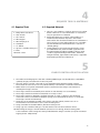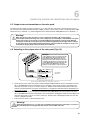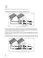
1
Solar
Charging Kit
SRV-50-KITUS
SRV-90-KITUS
SRV-135-KITUS
Solar
Expansion Kit
SRV-EXP-50-KITUS
SRV-EXP-90-KITUS
SRV-EXP-135-KITUS
Owner's
Manual
Please read
this manual
before
operating
your kit
Owner's Manual | Index
1.Introduction................................................................................ 3
2.
Components List......................................................................... 4
3.
General Safety............................................................................ 5
4.
Required Tools & Materials........................................................ 7
5.
Charge Controller Installation................................................... 7
6.
Connector System for Connecting Solar Panels....................... 8
7.Wiring...................................................................................... 12
8.
Solar Panel Installation........................................................... 15
9.
Connecting Solar Panels in Parallel........................................ 17
10. Typical Battery Connections................................................... 18
11.Warranty.................................................................................. 20
DETAILED PRODUCT INFORMATION
For a complete user manual including specifications, application notes, installation instructions, trouble shooting
and more, please visit the web page for this product on samlexamerica.com. Product page can be found using the
“search by model” field.
2
1
INTRODUCTION
Your new Samlex Solar Charging or Expansion Kit provides you with a clean,
green, silent and sustainable way to ensure your batteries are fully charged
and you have a continuous source of electricity while dry camping or in the
absence of a conventional electricity. Each kit comes with a high quality
solar panel, which produces DC electricity when illuminated by sunlight.
In a Solar Charging Kit, a state-of-the-art 30 Amp solar charge controller
is provided to be connected between the solar panel and the storage
batteries. The solar charge controller will make sure the battery is charged
with the harnessed solar electricity, as per the battery manufacturer’s
recommendations. The solar charge controller comes with eight selectable
charging profiles to meet the charging requirements of most standard
lead acid batteries used in RVs and remote off-grid solar applications, as
well as Nickel Cadmium (NiCad) batteries. The LCD screen on the charge
controller provides detailed information about the system status including
battery voltage and charging current. The solar charge controller is flush
mountable, which is ideal for mounting within the RV interior. The Samlex
Solar Charging Kit also includes a mounting system: sturdy aluminum
Z-brackets with the nuts and bolts required to flat mount the solar panel
on the roof of the RV or any other flat surface. If you wish to optimize
the collection of solar energy by tilting the solar panel to an optimal
inclination, an adjustable tilt-mount may be purchased separately. The cable
management hardware incorporated in the kit will enable you to effectively
manage any external wiring. To expand your system further and harness
more energy from the sun, you may use one of our Solar Expansion Kits
which come with a solar panel and all the hardware you need to mount the
extra solar panel and link it to the existing system.
This manual provides instructions on how to put together the various
components of the Samlex Solar Charging and Expansion kits. Please refer
to the separate solar charge controller manual for detailed information
about the installation, operation and programming of the solar charge
controller.
Please read the manual carefully before installing or operating the solar
kits to prevent personal injury or damage to the components. If you have
any concerns about the suitability of the kits for your application or doubts
about any of the instructions in the manual contact your authorized Samlex
America Distributor or Samlex America Technical Support at 1-800-561-5885.
3
2
COMPONENTS
No
4
Model
SRV-50-KITUS SRV-90-KITUS SRV-135-KITUS
SRV-EXP-50-KITUS
SRV-EXP-90-KITUS
SRV-EXP-135-KITUS
1
Samlex 50W Solar panel
1
0
0
1
0
0
2
Samlex 90W Solar panel
0
1
0
0
1
0
3
Samlex 135W Solar panel
0
0
1
0
0
1
4
Samlex 30 Amp Charge Controller
model SCC-30AB
1
1
1
0
0
0
5
Pre-assembled Positive (+) PV wire,
20 ft, AWG # 12 with male MC4
connector on one end
1
1
1
1
1
1
6
Pre-assembled Negative (-) PV
wire, 20 ft, AWG # 12 with female
MC4 connector on one end
1
1
1
1
1
1
7
MC4 Male Connector
0
0
0
1
1
1
8
MC4 Female Connector
0
0
0
1
1
1
9
Positive MC branch connector
0
0
0
1
1
1
10
Negative MC Branch Connector
0
0
0
1
1
1
11
5-hole mounting bracket
4
4
4
4
4
4
12
Stainless Steel Serrated Flange bolt
¼”-20 x ¾"
4
4
4
4
4
4
13
Stainless Steel Nylon
Insert Locknut, ¼”
4
4
4
4
4
4
14
Stainless Steel Flat washer, ¼”-20
8
8
8
8
8
8
15
Well Nut - Nut Thread: ¼”-20,
Length: 1”, Shank Dia.: ½”
4
4
4
4
4
4
16
Stainless Steel Serrated
Flange Bolt, ¼”-20x1¼”
4
4
4
4
4
4
17
Cable clamp
6
6
6
6
6
6
18
#8 Self Tapping Screws
6
6
6
6
6
6
19
Cable Ties
6
6
6
6
6
6
20
Battery Ring Terminals
2
2
2
2
2
2
21
Insulated Fork Terminals
4
4
4
0
0
0
22
7 x 19, 5/8" Flat Head Tapping
Screws
4
4
4
0
0
0
23
Samlex RV Kit
Installation Manual
1
1
1
1
1
1
3
GENERAL SAFETY
3.1. Warnings
Please read the instruction manual carefully before attempting to carry out
any installation and wiring. Contact your RV dealer or Technical support at
Samlex America (1-800-561-5885) for any questions concerning the installation.
Installation and wiring compliance
Installation and wiring must comply with the local and National Electrical Codes and must be done
by a certified electrician.
1. Disconnect all power sources before carrying out the installation.
2. Make sure the correct polarity is observed when making connections between the solar panel,
charge controller and the battery. Damage due to reverse polarity connection is not covered
by warranty.
3. Make sure all wire connections are secure as loose connections may cause sparks.
4. Wear appropriate clothing and safety gear including protective eyewear when performing
any electrical installation.
Preventing fire and explosion hazards
Working with electronic/electrical equipment may produce arcs or sparks. Thus, such equipment should not
be used in areas where there are inflammable materials or gases requiring ignition protected equipment.
These areas may include spaces containing gasoline powered machinery, fuel tanks, battery compartments.
Precautions when working with batteries
• Batteries contain very corrosive diluted sulphuric acid as electrolyte. Precautions should be taken
to prevent contact with skin, eyes or clothing.
• Batteries generate hydrogen and oxygen during charging resulting in evolution of explosive gas mixture.
Care should be taken to ventilate the battery area and follow the battery manufacturer’s
recommendations.
• Never smoke or allow a spark or flame near the batteries.
• Use caution to reduce the risk of dropping a metal tool on the battery. It could spark or short circuit
the battery or other electrical parts and could cause an explosion.
• Remove metal items like rings, bracelets and watches when working with batteries. The batteries can
produce a short circuit current high enough to weld a ring or the like to metal and thus cause a severe
burn.
• If you need to remove a battery, always remove the ground terminal from the battery first. Make sure
that all the accessories are off so that you do not cause a spark.
• Use properly insulated tools only when making battery connections.
Precautions when working with solar panels
With the incidence of sunlight or other light sources on all solar panels, a voltage appears at the output
terminals of the solar panel turning it into a source of electricity. To avoid a shock hazard make sure the solar
panel is covered with an opaque (dark) material such as paper/cloth during the installation. Do not make
contact with the terminals when the panel is exposed to sunlight or any other light sources.
5
3
GENERAL SAFETY
Precautions when working with Charge Controller Model no. SCC-30AB
If two or more solar panels are connected in series/parallel make sure that the sum of the short circuit current
ratings of all panel strings does not exceed 80% of the charge controller’s current rating i.e. 24 Amps for the
30 Amp charge controller. The open circuit voltage of the solar array i.e. the maximum voltage across the array
should not exceed 26 V when the 12 V setting on the charge controller is used and not exceed 52 V when the
24 V setting on the charge controller is used.
3.2. Routine Maintenance
• Inspect the solar panels and make sure the surface is free from dust, dirt and other debris,
clean with a wet cloth or glass cleaner, if necessary.
• Check to make sure all structural components, mechanical fasteners and electrical connections are
secure, clean and corrosion-free.
• Check and maintain the battery electrolyte levels at regular intervals as per the battery manufacturer’s
recommendations if flooded wet cell lead acid batteries are used.
• Check and replace damaged components if necessary.
3.3. Installation Overview
1. Read the manual in detail and understand the installation procedure.
2. Open the packaging and check to make sure that all parts have been received as per the parts list
in the manual.
3. Arrange for the required tools to carry out the installation. A sample list of tools (not exhaustive)
is provided in Section 4.
4. Determine the mounting location of the solar panel(s) on the roof of the RV.
5. Mount the charge controller at the desired location (see Section 5).
6. Pass the cable from the solar panels to the interior of the RV (See section 6).
7. Wire the battery to the charge controller and then the solar panel to the charge controller ensuring
the correct polarity is observed (See Section 6).
8. Secure the solar panel to the RV roof (See Section 7).
solar
panel
solar
charge
controller
battery
Fig. 3.3. Installation Block Diagram
6
4
REQUIRED TOOLS & MATERIALS
4.1. Required Tools
1. Philips drive screw driver
2. 7/16” wrench
3. 3/8” wrench
4. Wire stripper
5. Wire crimping tool
6. Hand Drill
7. ½” drill bit
8. Jig-saw or suitable cutting tool
9. Pliers
10.Punch or Awl
4.2. Required Materials
1. Silicone or any suitable roof sealant. Contact your local RV
dealer or RV store for a recommendation on a sealant to
suit your specific RV roof material.
2. Anti-galling lubricant to prevent “thread galling” of
all stainless steel fasteners exposed to the outdoor
environment. This should be available at most hardware or
auto-parts stores. If anti-galling lubricant is not available
any standard lubricant will minimize the occurrence of
“thread galling”.
3. If wiring distances are longer than the lengths of wire
provided with the kit, extra stranded copper wire will
be required. Wires should be 12 AWG or thicker, single
conductor, Type UF (Underground Feeder - marked as
sunlight resistant), Type SE (Service Entrance) or Type USE/
USE-2 (Underground Service Entrance).
5
CHARGE CONTROLLER installation
1. The Samlex Solar Charging Kit comes with a 30 Amp PWM charge controller Model no. SCC-30AB to
optimally charge your batteries from the solar panel.
2. The Solar charge controller comes with its own detailed manual. Read the manual in detail.
The instructions in this section are only a brief summary of information contained in the manual.
3. Make sure the solar panels and batteries are disconnected from the charge controller before
installing the charge controller.
4. The charge controller should ideally be located in an area relatively close to the battery.
5. The charge controller should be mounted indoors in a dry location.
6. The charge controller is designed to be flush mounted on a wall or cabinet so that the wiring
at the back can be accessed. Allow adequate spacing (2-3 inches) behind the unit to accommodate
the charge controller and the wiring.
7. Using the cut-out template provided in the charge controller manual, mark the cut-out on
the installation surface and the location of the mounting holes.
8. Using a hand drill and suitable drill bit, drill the mounting holes.
9. Using a jig saw or suitable cutting tool cut the material out from the installation surface.
10.After wiring the charge controller terminals (see Section 6 on wiring), fix the mounting plate
to the installation surface using the screws provided with the charge controller (7 x 19, 5/8" Flat Head
Tapping Screws - Philips Drive).
7
6
CONNECTOR SYSTEM FOR CONNECTING SOLAR PANELS
The Positive and Negative outputs of a solar panel are fed through a water tight junction box. Appropriate
size of wires are wired to the junction box for further connections.The solar panels supplied with these kits are
provided with approximately 3 ft. each of Positive & Negative wires that are pre-connected to the junction box.
The free ends of the wires are terminated with special mating type of connectors for ease of extending these
wires for further connections. The special mating type of connectors used for the 3 ft. wires provided with the
solar panels and also for the separate extension wires are as follows:
• "SolarLine - MC4" Series manufactured by Multi Contact
• "Helios - H4" -Series manufactured by Amphenol
Both of above "MC4" & "H4" Series are interchangeable and any one of these may be used in these kits. In this
manual, MC-4 Series will be used for explanations.
6.1. General Information on MC4 Connector System
MC4 Connector System consists of male and female connectors. This type of connector system is easy to
install and uses “snap-in” type of safety locking clips to lock the two mating connectors, thereby, avoiding
unintentional disconnection. Also, the mating contacts are sealed against ingress of dust and water.
Specifications are as follows:
• Contact diameter Ø 4 mm
• Maximum rated current - 30 A
• Maximum system voltage - 1000 V
• Degree of ingress protection when connected and properly locked - IP67
• Temperature range 40°C to +90°C
• TÜV Rheinland – type approved
6.2. MC4 Connectors (Fig. 6.2)
The MC4 Connectors mentioned in this manual have been designated “Male” and “Female” based on the
characteristics of the mating contact inserts inside the terminals.
In the MC4 Male Connector (1 of Fig. 6.2), the internal mating contact insert (2, Fig. 6.2) is a male pin. It has
two slots (3 of Fig. 6.2) for insertion of the two “snap-in” type of locking tabs (6 of Fig. 6.2) of the MC4 Female
Connector (4 of Fig. 6.2) for firm mating connection. This connector is marked "-".
In MC4 Female Connector (4, of Fig. 6.2), the internal mating contact insert (5 of Fig. 6.2) is a female cylindrical
socket. It has two “snap-in” type of locking tabs (6 of Fig. 6.2) that are inserted into the two slots (3 of Fig. 6.2)
in the MC4 Male Connector (1 of Fig. 6.2) for firm mating connection. Wire is crimped to the contact inserts (2
and 5 of Fig. 6.2) using a special purpose crimping tool designed for MC4 connectors. After the wire has been
crimped, the contact insert is required to be seated securely inside the housing and the strain relief / seal (7 of
Fig. 6.2) is to be tightened fully to provide a water-tight seal.
7
1
3
2
3
6
7
4
5
6
1. MC4 Male connector (marked “-”)
2. Male contact insert
3. Slots for accepting “snap-in” type of locking tabs of the mating MC4 female connector
4. MC4 Female connector (marked “+”)
5. Female contact insert
3. “Snap-in” type of locking tabs of the mating with the slots on the MC4 female connector
7. Strain relief and seal
Fig. 6.2. MC4 Male and Female Connectors
Note: Additional pairs of male/female MC4 connectors are also sold separately (Model No. "MC4-2 Kit")
8
6
CONNECTOR SYSTEM FOR CONNECTING SOLAR PANELS
6.3. Output wires and connections on the solar panel
Fig. 6.4 shows the output wires and connections on a solar panel. The output wires from the junction box of
the solar panel are terminated with the help of MC4 connectors. The Positive (+) wire is terminated with a MC4
Female Connector (marked "+") and the Negative wire is terminated with a MC4 Male Connector (marked "-").
Warning!
When the surface of the solar panel / array is exposed to sunlight, a DC voltage appears
at the output terminals turning it into a live voltage source. For example, a 24 V nominal solar panel
my put out an open circuit voltage of around 45 VDC that may produce electrical shock. Multiple
solar panels connected in series (to increase the output voltage) will put out higher lethal voltages
To avoid any electrical shock hazard during installation, make sure that the solar panel / array is covered with an opaque (dark) material to block solar irradiation.
6.4. Extending to the output wires of the solar panel (Fig. 6.4)
Caution!
*1. Note that the Positive (+) extension wire has
a male MC4 mating connector marked (-) that
mates with the female MC4 mating connector
marked (+) on the Positive (+) wire of the panel.
*2. Similarly, the Negative (-) extension wire has
a female MC4 mating connector marked (+) that
mates with the male MC4 mating connector
marked (-) on the Negative (-) wire of the panel.
*2
Male MC4 mating
Female MC4 mating connector
connector marked (-) marked (+) for Negative (-)
PV Extension wire
To external
PV circuit
*1
Female MC4 mating Male MC4 mating connector
connector marked (+) marked (-) for Positive (+)
PV Extension wire
Fig 6.4. Connecting extension wires to the output wires of solar panel
1. The Positive (+) wire of the solar panel is terminated with a MC4 Female Connector (marked +). Connect
this to the MC4 Male Connector (marked -) that is attached to the Positive extension wire. Make sure
that the locking tabs “snap in” for a firm connection. The bare end of the Positive extension wire will
now be of Positive polarity. Use a piece of red sleeve or red tape near the bare end for identification as
the Positive (+) wire.
2. The Negative (-) wire of the solar panel is terminated with a MC4 Male Connector (marked -). Connect
this to the MC4 Female Connector (marked +) that is attached to the Negative extension wire. Make sure
that the locking tabs “snap in” for a firm connection. The bare end of the Negative extension wire will
now be of Negative polarity.
3. Connect the two wires to the external PV circuit.
Warning!
Ensure that the polarity (+ or -) of the wires is identified correctly before connecting to a circuit or a
device. Damage due to wrong polarity may not be covered under warranty.
9
6
CONNECTOR SYSTEM FOR CONNECTING SOLAR PANELS
6.5. Connecting two adjacent solar panels in parallel (Fig. 6.5)
SBC-2 Kit
MC4 female
branch connector (-)
SCW-20-2 Kit
To external
PV circuit
MC4 male
branch connector (+)
Fig. 6.5. Connecting two adjacent solar panels in parallel
Two or more solar panels can be connected in parallel to increase the current output at the same output
voltage. Fig. 6.5 above shows the arrangement for connecting two solar panels in parallel using the SCW-20-2
Connecting Wire Kit and the MC4 Branch Connector Kit (SBC-2) sold separately. This arrangement is applicable
if the two solar panels are to be mounted adjacent to each other.
The output wires of the two solar panels are first connected in parallel using the MC4 Male and Female Branch
Connectors. The outputs of the Branch Connectors are then connected to the SCW-20-2 wires for connecting to
the external PV circuit.
6.6. Connecting two solar panels in parallel when separated by a distance (Fig. 6.6)
SBC-2 Kit
SCW-20-2 Kit
Male MC4
connector
MC4 female
branch connector (-)
SCW-20-2 Kit
To external
PV circuit
Female MC4
MC4 male
connector
branch connector (+)
Fig. 6.6. Connecting two solar panels in parallel that are separated by an extended distance
10
6
CONNECTOR SYSTEM FOR CONNECTING SOLAR PANELS
Fig. 6.6 above shows an arrangement for connecting two solar panels in parallel that are separated by an
extended distance. In this case, the following will be required:
• SCW-20-2 Connecting Wires Kit - 2 sets
• One MC4 Male Branch Connector and one MC4 Female Branch Connector sold separately as an optional
kit – Model No. “SBC-2” Kit
• One MC4 Male Connector and one MC4 Female Connector sold separately as an optional kit – Model No.
“MC4-2“
In this case, one Connecting Wire Kit “SWC-20-2” and the optional MC-4 Connectors Kit “MC4-2” are first used
to bridge the extended distance between the panels. The optional Branch Connector “SBC-2” Kit is used to
parallel the two solar panels. The second Connecting Wire Kit “SWC-20-2” is used to connect to the external PV
circuit.
11
7
WIRING
Caution!
The battery must be wired to the charge controller before the solar panel is connected to
the charge controller.
A pair of 20 foot pre-assembled cables with Multi-Contact (MC) male and female connectors is provided
primarily to connect the solar panel to the charge controller. After making sure that sufficient length is
available to wire the solar panel to the charge controller, any excess wire maybe used to wire the battery to
the charge controller.
7.1. Battery to Charge Controller
• Mark the cables to differentiate between Positive and Negative.
• Make sure the Positive terminal (marked ‘+’) of the battery is connected to the Positive terminal (marked
“BAT +”) of the charge controller and the negative terminal (marked ‘-’) of the battery is connected to
the Negative terminal (marked “BAT -”) of the Charge Controller SCC-30AB (Fig. 7.1.1). If you are not
sure use a DC voltmeter to determine the polarity of the battery bank. Reverse polarity connection will
damage the Charge Controller and the resulting damage will not be covered by warranty.
• Crimp the insulated fork terminals provided (Fig. 7.1.3) to one end of the Positive and Negative battery
leads.
• Insert the fork terminals (Fig. 7.1.3) into the appropriate terminal on the charge controller: Positive
lead is connected to the Positive terminal (marked “BAT+”) of the charge controller Negative lead is
connected to the Negative terminal (marked “BAT -”) of the Charge Controller SCC-30AB (Fig. 7.1.1).
• Crimp the battery ring terminals (Fig. 7.1.2) provided to the Positive and Negative wire leads to be
connected to the battery terminals.
• Clean the battery post terminals free of corrosion and other impurities.
• Bolt the ring terminals to the battery terminals making sure the correct polarity is observed.
Warning:
Be careful not to short the battery
PV +
PV BAT+
BAT PV +
PV BAT+
Bat
Bat BAT
12
Fig 7.1.1 Rear view
of Solar Charge
Controller showing
terminals
Fig 7.1.2
Battery
Ring
terminal
Fig 7.1.3
Fork
terminal
7
WIRING
7.2. Solar Panel to Charge Controller
1. Determine the position of the solar panel on the RV roof. While positioning panels, avoid shading of the
solar panel by neighbouring obstacles such as vents, air-conditioners, TV antennas etc. As far as possible,
position the panels to minimize wiring distance between the solar panel and the charge controller. Place
the panel at least 8-10 inches away from the RV roof edges and leave sufficient space to walk around the
panel and access the mounting hardware.
2. Make sure the thickness of the roof at the installation location is at least ½” thick and the material
is strong enough to provide mechanical support to the solar panel and mounting hardware against
possible wind loading. Place the panel length-wise to reduce the effects of wind loading on the RV.
2
1
1. Negative wire with MC4 Female connector (marked “+”)
2. Positive wire with MC4 Male connector (marked “-”)
Fig. 7.2. PV extension wires
3. Two pre-assembled, 20 ft, AWG #12, Positive (+) & Negative (-) PV extension wires have been provided
(see Fig. 7.2). The wires have MC4 mating connectors on one end for connecting to the solar panel &
bare ends on the other side for connecting to the Charge Controller. The wires are marked (+) & and (-)
for identification of the polarity.
4. Please read sections 6.3 & 6.4 on connecting the extension wires to the panels.
refrigerator
vent cover
solar
panel
vent
screen
method B
method A
Fig. 7.3. PV extension entry through RV Vent
13
7
WIRING
5. The wire pair from the solar panel can be routed to the interior of the RV through the roof-top
refrigerator vent. Find where the refrigerator vent is located on the roof of the RV. See Fig. 7.3.
6. Select a suitable mounting location for the solar panel, preferably as close to the vent as possible. The
mounting surface should be strong enough to support the mounting hardware, the solar panel and
wind loads.
7. Take off the vent cover to gain access to the duct opening and keep the vent fastening hardware safely
as the vent cover will have to be replaced after the wires have been routed.
8. The
wires from the solar panel can be routed by either:
A. Hole in the side of the vent: Drill a suitable hole in the side of the vent and insert a rubber grommet (not provided). Route the wire pair carefully to the charge controller through the hole. Use appropriate sealant as recommended by your local RV dealer to ensure the penetration at the side of the vent is watertight.
B. Through the vent screen: Route the wire pair through the vent screen grid holes. Widen the screen grid holes if necessary.
9. Use the cable clamps with #8 self-tapping screws and tie wraps at regular intervals of the wire route
from the solar panel to the charge controller to hold the cables in place for a neat finish. Tuck any excess
wire under the refrigerator vent cover.
Warning:
Avoid sharp, heated or abrasive material on the cable route.
10.Replace the refrigerator vent cover and secure with the retained hardware.
11.Crimp the bare end of the wires with the fork terminals provided (Fig 7.1.3).
12.Insert the terminals into the appropriate terminal on the charge controller (Fig 7.1.1): positive PV lead
is connected to the positive terminal (marked “PV +”) of the charge controller and the negative PV
lead is connected to the negative terminal (marked “PV -”) of the charge controller. Reverse polarity
connection will damage the Charge Controller and the resulting damage will not be covered by
warranty.
14
8
SOLAR PANEL INSTALLATION
1. Stainless steel can be subject to a process called “thread
galling” in which bolts can twist off and/or the bolt
threads seize to the nut’s thread. Apply Anti-galling
lubricant available at most hardware or auto-parts stores
to all the stainless steel fasteners before installation.
If anti-galling lubricant is not available, any standard
lubricant will minimize the occurrence of “thread
galling”.
2. Fix the mounting brackets (Fig. 8.2) to the frame of
the previously positioned solar panel using the slotted
opening and the ¼”-20 x ¾"Flange Bolt, Nylon Locknut
and flat washer (Fig. 8.1).
3. Using a 7/16” wrench, tighten the nuts to secure the
mounting brackets to the PV panel. Recommended
tightening torque is 15 lbs.
4. Position the panel with the attached mounting brackets
at the desired location on the RV roof and mark the
position of the desired mounting hole using a suitable
marker by tracing the hole on the mounting bracket.
Please ensure that the mounting surface on the RV roof is
strong enough to support the mounting hardware, solar
panel and wind loads.
5. The centre and end holes on the mounting brackets (Fig.
8.2) are sized to accept the ¼” hardware supplied with
the unit. If the use of larger sized hardware is desired,
holes 2 and 4 can be used.
solar module
1/4” -20x3/4” flange bolt
1/4” flat washer
mounting bracket
1/4” locknut
RV roof
Fig. 8.1. Attaching solar panel to 5-hole mounting bracket.
1/4” holes
3/8” holes
Fig. 8.2. 5-Hole Mounting Bracket.
Well Nut for anchoring Solar Panel to RV Roof
6. A Well-Nut is a bushing of tough neoprene rubber with
a flange at the top end and a captive brass nut mounted
within the bore at the bottom end (Fig. 8.3). Tightening a
conventional machine bolt or screw engages the captive
nut thereby causing the bushing to expand outwards.
This fastens securely to thinner RV roofs by bulging up
and against the bottom surface of the roof (Fig. 8.6). If
used in a blind hole in a solid surface material, the rubber
will expand outwards to create a secure fastening (Fig.
8.7). The neoprene and brass resist most environmental
conditions. Additionally, the Well-Nut seals the drilled
hole effectively against air and liquid leakage.
flange
1/2” diameter
1/4” captive brass nut
Fig. 8.3. Construction of a Well Nut
15
8
flange
flange flange flange
1/2” diameter
1/2” diameter
1/2” diameter
1/2” diameter
SOLAR PANEL INSTALLATION
1/4” captive brass nut
1/4” captive
1/4” captive
brass
1/4”
nut
brass
captive
nutbrass nut
Typical Installation of a Well-Nut
Fig. 8.4. Well-Nut is inserted into
a pre-drilled hole with its flange
against the outer surface. There
is no need for access to the
inner side.
Fig. 8.5. The 5-hole mounting
bracket is placed against the flange
of the Well-Nut and is secured
by the bolt engaging the captive
brass nut.
Fig. 8.6 . As the bolt is tightened, the
neoprene body of the Well-Nut is
compressed and expanded, forcing
it tightly into the bolt's threads and
against the inner surface of the thin RV
roof material.
Fig. 8.7. Installed in a blind
hole in a solid material, the
body of the Well-Nut expands
tightly against the walls of
the hole, effecting a secure,
dependable fastening.
7. To install the Well-Nuts, drill holes 1¼” deep at the marked positions using a ½” size drill bit. Make sure
that drilling does not interfere with pre-existing wiring installations.
8. Apply silicone or any appropriate sealant recommended by your RV dealer generously to the drilled
holes for water-proofing.
9. Insert the ¼” Well-Nut into the drilled holes so that only the flange section remains above the roof
surface (Fig. 8.4).
10.Fasten the mounting brackets to the roof surface by inserting the ¼ x 1¼” serrated flange bolt into the
Well-Nut (Fig. 8.5). Tighten using a 3/8” wrench to a recommended torque of 15 lbs. When the serrated
flange bolt is screwed into the Well-Nut, the material surrounding the well nut bulges slightly securing
the structure to the RV roof (Fig. 8.6 & 8.8).
11.Make sure all bolts and mounting brackets are covered by good amounts of suitable RV sealant
recommended by your local RV dealer.
mounting bracket
¼”-20 x 1¼” flange bolt
¼” flat washer
Well-Nut
solar
module
RV roof material
up to approx. 3/8”
thickness
Rubber bushing material expands
when bolt is tightened to securely
anchor hardware
Fig. 8.8 Attaching 5-hole mounting bracket to RV Roof
16
9
connecting Solar panels in parallel
The Samlex Expansion kits maybe used
to increase the solar energy available
to charge your batteries. Each Samlex
Expansion kit comes with a solar
panel, mounting hardware for the
solar panel and a set of MC male and
female branch connectors to parallel
the solar panel to your existing system.
1. If the existing panel is already
connected to the mating
connector on the pre-assembled
cables provided in the original
kit, remove this connection
using using a tweezer or any
other suitable tool.
2. Connect the Positive leads
(marked as ‘+’) from the two
solar panels to the suitable
mating branch connector (as in
Fig 9.1).
3. Connect the Negative leads
(marked as ‘-’) from the two
solar panels to the suitable
mating branch connector (as in
Fig 9.1).
4. Mate the MC branch connectors
to the corresponding mating
MC connector on the preassembled cables provided with
your original kit.
If the additional solar panels are
required to be mounted at a distance
from the existing solar panel, a pair
of cables with a MC4 connector preassembled at one end is provided.
1. Cut the cable pair to the
appropriate length.
2. Strip 0.25" of the insulation at
the blunt ends using a suitable
wire stripper.
3. Crimp the male and female MC4
connector to the blunt end of
the appropriate cable with a
suitable wire crimping tool.
4. Complete the connections as
shown in Fig. 9.2.
SBC-2 Kit
MC4 female
branch connector (-)
SCW-20-2 Kit
To external
PV circuit
MC4 male
branch connector (+)
Fig. 9.1. Connecting solar modules in parallel.
SBC-2 Kit
SCW-20-2 Kit
Male MC4
connector
MC4 female
branch connector (-)
SCW-20-2 Kit
To external
PV circuit
Female MC4
MC4 male
connector
branch connector (+)
Fig. 9.2. Connection solar modules in parallel with additional module.
17
10
TYPICAL BATTERY CONNECTIONS
10.1. Series Connection of Batteries
Cable “A”
PV +
PV BAT+
BAT -
Solar Charge Controller
SCC30-AB (rear view)
Cable “A”
Battery 1
Battery 2
6V Battery
6V Battery
Cable “B”
“A” Connection
Fig. Cable
10.1. Series
Battery 1
Battery 1
Battery 2
Battery 2
Battery 3
Battery 4
When two or more batteries are connected in series, their voltages add up but their AH capacity remains the
+
PV +2 pieces ofPV
same. Fig. 10.1 above shows
PV6 -V, 200 AH batteries connected in series to form a battery bank of 12
PV V with a capacity of 200 AH.
of Battery6V12V
1Battery
becomes
the Positive
terminal of the
12 V bank.
BAT+The Positive
BAT+terminal
6V Battery
Battery
12V Battery
12V Battery
BAT BAT The negative terminal of Battery
1 is connected
to the Positive terminal of Battery 2. The negative terminal of
Battery 2 becomes the negative terminal of the 12 V battery bank.
12V Battery
Solar Charge Controller
10.2. Parallel
Connection
ofController
Batteries
SCC30-AB
(rear Solar
view) Charge
SCC30-AB (rear view)Cable “B”
Cable “A”
PV +
PV BAT+
BAT -
Cable “B”
Battery 1
Battery 2
12V Battery
12V Battery
Battery 1
Battery 3
String 1
12V Battery
Battery 4
12V Battery
String 2
Battery 2
Battery 3
Battery 4
6V Battery
String 2
6V Battery
6V Battery
Cable “A”
Solar Charge Controller
SCC30-AB (rear view)
Cable “B”
PV +
PV BAT+
BAT -
Fig. 10.2. Parallel Connection
String 1
6V Battery
When two or more batteries are connected in parallel, their voltage remains the same but their AH capacities
add up. Fig. 10.2 shows 4 pieces of 12 V, 100 AH
batteries
connected
to3 form a battery
Battery
1
Battery 2 in parallel
Battery
Battery 4 bank of
12 V with a capacity of 400 AH. The
four
Positive
terminals
of
Batteries
1
to
4
are
paralleled
(connected
Cable “A”
Solar
Chargeconnection
Controller becomes the Positive terminal of the 12 V bank. Similarly, the
together) and this common
Positive
view)
four Negative terminals ofSCC30-AB
Batteries(rear
1 to
4 are paralleled (connected together) and this common Negative
PV +
Cablebank.
“B”
connection becomes the Negative
terminal of the 12 V battery
PV BAT+
BAT -
6V Battery
Solar Charge Controller
SCC30-AB (rear view)
Cable “B”
18
6V Battery
6V Battery
6V Battery
PV BAT+
BAT -
6V Battery
Solar Charge Controller
SCC30-AB (rear view)
6V Battery
Cable “B”
Cable “A”
PV +
PV BAT+
BAT -
Battery 1
Battery 2
12V Battery
12V Battery
Battery 3
Battery 4
12V Battery
12V Battery
10
TYPICAL BATTERY CONNECTIONS
Solar Charge Controller
SCC30-AB (rear view)
10.3. Series – Parallel ConnectionCable
of“B”Batteries
String 1
String 2
Battery 1
Battery 2
Battery 3
Battery 4
6V Battery
6V Battery
6V Battery
6V Battery
Cable “A”
PV +
PV BAT+
BAT -
Solar Charge Controller
SCC30-AB (rear view)
Cable “B”
Fig. 10.3. Series-Parallel Connection
Figure 10.3 above shows a series – parallel connection consisting of four 6 V, 200 AH batteries to form a 12 V,
400 AH battery bank. Two 6 V, 200 AH batteries, Batteries 1 and 2 are connected in series to form a 12 V, 200
AH battery (String 1). Similarly, two 6 V, 200 AH batteries, Batteries 3 and 4 are connected in series to form a 12
V, 200 AH battery (String 2). These two 12 V, 200 AH Strings 1 and 2 are connected in parallel to form a 12 V,
400 AH bank.
CAUTION!
When 2 or more batteries / battery strings are connected in parallel and are then connected to
the Solar Charge Controller SCC30-AB (See Figs. 10.2 and 10.3 given above), attention should be
paid to the manner in which the solar charge controller is connected to the battery bank. Please
ensure that if the positive output cable of the solar charge controller (Cable “A”) is connected
to the positive battery post of the first battery (Battery 1 in Fig. 10.2) or to the positive battery
post of the first battery string (Battery 1 of String 1 in Fig. 10.3), then the Negative output cable
of the Solar Charge Controller SCC30-AB (Cable “B”) should be connected to the Negative battery post of the
last battery (Battery 2 as in Fig. 10.2) or to the Negative Post of the last battery string (Battery 4 of Battery
String 2 as in Fig. 10.3). This connection ensures the following:
• The resistances of the interconnecting cables will be balanced.
• All the individual batteries / battery strings will see the same series resistance.
• All the individual batteries will charge at the same charging current and thus,
will be charged to the same state at the same time.
• None of the batteries will see an overcharge condition.
If the positive output cable of the battery charger (Cable “A”) is connected to the positive battery post of the first
battery (Battery 1 in Fig. 10.2) or to the positive battery post of the first battery string (Battery 1 of String 1 in Fig.
10.3), and the Negative output cable of the battery charger (Cable “B”) is connected to the Negative battery post
of the first battery (Battery 1 as in Fig. 10.2) or to the Negative Post of the first battery string (Battery 1 of Battery
String 1 as in Fig. 10.3), the following abnormal conditions will result:
• The resistances of the connecting cables will not be balanced.
• The individual batteries will see different series resistances.
• All the individual batteries will be charged at different charging current and thus,
will reach fully charged state at different times.
• The battery with lower series resistance will take shorter time to charge as compared to the battery which
sees higher series resistance and hence, will experience over charging and its life will be reduced.
19
11
warranty
Warranty
The Samlex Solar Charging and Expansion Kits manufactured by Samlex America, Inc. (the “Warrantor“) are warranted to be free from defects in workmanship and materials under normal use and service. The warranty is in
effect from the date of purchase by the user (the “Purchaser“).
Warranty period for various kit components:
50W/90W/135W Solar Panel: 5 year product workmanship warranty
12 year 90% power output warranty
25 year 80% power output warranty
Samlex 30 Amp Solar Charge Controller
Model SCC-30AB:
5 year product workmanship warranty
Mounting Hardware and Wiring:
5 year product workmanship warranty
Warranty outside of the United States and Canada is limited to 6 months. For a warranty claim, the Purchaser
should contact the place of purchase to obtain a Return Authorization Number.
The defective part or unit should be returned at the Purchaser’s expense to the authorized location. A written
statement describing the nature of the defect, the date of purchase, the place of purchase, and the Purchaser’s
name, address and telephone number should also be included.
If upon the Warrantor’s examination, the defect proves to be the result of defective material or workmanship,
the equipment will be repaired or replaced at the Warrantor’s option without charge, and returned to the Purchaser at the Warrantor’s expense. (Contiguous US and Canada only)
No refund of the purchase price will be granted to the Purchaser, unless the Warrantor is unable to remedy the
defect after having a reasonable number of opportunities to do so. Warranty service shall be performed only by
the Warrantor. Any attempt to remedy the defect by anyone other than the Warrantor shall render this warranty
void. There shall be no warranty for defects or damages caused by faulty installation or hook-up, abuse or misuse
of the equipment including exposure to excessive heat, salt or fresh water spray, or water immersion.
No other express warranty is hereby given and there are no warranties which extend beyond those described
herein. This warranty is expressly in lieu of any other expressed or implied warranties, including any implied warranty of merchantability, fitness for the ordinary purposes for which such goods are used, or fitness for a particular purpose, or any other obligations on the part of the Warrantor or its employees and representatives.
There shall be no responsibility or liability whatsoever on the part of the Warrantor or its employees and representatives for injury to any persons, or damage to person or persons, or damage to property, or loss of income or
profit, or any other consequential or resulting damage which may be claimed to have been incurred through the
use or sale of the equipment, including any possible failure of malfunction of the equipment, or part thereof. The
Warrantor assumes no liability for incidental or consequential damages of any kind.
Samlex America Inc. (the “Warrantor”)
www.samlexamerica.com
20
NOTES:
Contact
Information
Toll Free Numbers
Ph: 800 561 5885
Fax: 888 814 5210
Local Numbers
Ph: 604 525 3836
Fax: 604 525 5221
Website
www.samlexamerica.com
USA Shipping Warehouse
Kent WA
Canadian Shipping Warehouse
Delta BC
Email purchase orders to
[email protected]
11013-SRV-50-90-135-KITUS-1112 EN
MAN-10001