1
Development of an intuitive sound manipulation tool
for in-vehicle human-machine interaction design
Master’s Thesis in Intelligent System Design
Jiaxin Wang
Department of Applied Information Technology
CHALMERS UNIVERSITY OF TECHNOLOGY
Gothenburg, Sweden, 2009
Report No. 2012:82
ISSN: 1651-4769
II
Thesis for the Degree of Master of Science
Development of an intuitive sound manipulation tool
for in-vehicle human-machine interaction design
Jiaxin Wang
Department of Applied IT
Chalmers University of Technology
Gothenburg, Sweden 2012
III
Development of intuitive sound manipulation tool for in-vehicle Human Machine Interaction
design
Jiaxin Wang
© Jiaxin Wang, October 2012.
Report No. 2012:082
ISSN: 1651-4769
Chalmers University of Technology
University of Gothenburg
Department of Applied IT
SE-412 96 Göteborg
Sweden
Telephone + 46 (0)31-772 1000
Reproservice / Department of Applied IT
Göteborg, Sweden
October 2012
IV
Development of an intuitive sound manipulation tool for in-vehicle human-machine interaction
design
Jiaxin Wang
Department of Applied IT
Chalmers University of Technology
Abstract
Intuitive sounds such as auditory icons are known to be more efficient than abstract sounds
(earcons) in conveying driver relevant information. Further, different traffic situations may be of
different urgency levels and also related to the driver’s performance. Hence auditory information
may have to be changed or manipulated in order to convey the appropriate level of urgency.
However, very few authors address the problem of appropriately designing auditory icons and
how they should be manipulated to convey different urgency levels. This thesis work has been
conducted in order to develop a signal processing tool which could be used for such design and
evaluation. The tool is designed to take different sensory data (as distance to a leading vehicle)
as the input and use that data to manipulate a catalogue of sound signals. The goal of the thesis is
to let these sound signals inform the driver about the current traffic situation with the right level
of urgency.
Keywords: Auditory Icons, Human Machine Interaction, Real-time Audio Manipulation,
C# Programming
I
PREFACE
This thesis work has been carried out as part of the Environmental Friendly efficient Enjoyable
and Safety Optimized Systems (EFESOS) project. The main project partners are Semcon AB and
Chalmers University of Technology.
ACKNOWLEDGEMENTS
I would like to thank my supervisor, Per-Göran Åkesson from Semcon AB, for offering this
thesis work and his advices concerning software requirements and structure. I would also like to
thank my examiner Professor Claes Strannegård from Chalmers University of Technology for his
great inputs to the thesis work and report.
I would like to thank Minjuan Wang, a PHD student from Chalmers, and also like to thank
colleagues, Ingmar, Jonas, Peter and Vjendra from Semcon, who have provided great support
and insightful ideas. Their ideas have influenced most part of the language choosing, GUI design
and software functionality. Especially, Peter and Vjendra supported me with great help in report
writing.
Last but not the least; I would like thank my parents and all my friends. They have always been
supportive. I am very grateful.
II
Table of Contents
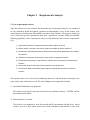
Chapter 1
Introduction ............................................................................................................................... 1
1.1 Background ......................................................................................................................................... 1
1.2 Purpose and structure of the thesis ...................................................................................................... 2
Chapter 2
Requirements Analysis .............................................................................................................. 5
2.1 User requirements analysis ................................................................................................................. 5
2.2 Programming language ....................................................................................................................... 8
2.3 Software requirements specifications ................................................................................................. 9
2.3.1 Sound editing of auditory icons ................................................................................................... 9
2.3.2 Intuitive sound effects ................................................................................................................ 10
2.3.3 Traffic tracking and intuitive sound triggering .......................................................................... 10
2.3.4 Graphical user interface and user controls ................................................................................. 11
2.3.5 Open structure for future development ...................................................................................... 11
Chapter 3
Software Design ...................................................................................................................... 13
3.1 Design concept .................................................................................................................................. 13
3.2 Software structure ............................................................................................................................. 14
3.2.1 Real time processing module ..................................................................................................... 14
3.2.2 Communication module: ............................................................................................................ 16
3.2.3 Tracking and triggering module:................................................................................................ 17
3.2.4 User interface ............................................................................................................................. 18
3.3 Data structure .................................................................................................................................... 23
Chapter 4
Implementation........................................................................................................................ 25
4.1 Real-time sound manipulation module ............................................................................................. 25
4.1.1 Sound manipulation ................................................................................................................... 26
4.1.2 Sound mixing ............................................................................................................................. 27
4.2 Communication module - Working with STISIM ............................................................................ 29
4.2.1 Data Structure on the serial port ................................................................................................ 29
4.2.2 STISIM scenario switch ............................................................................................................. 30
4.3 Tracking and trigger module ............................................................................................................. 31
4.3.1 Tracking process ........................................................................................................................ 31
4.3.2 Trigger process........................................................................................................................... 32
Chapter 5 Verification and Future Development ........................................................................................ 35
5.1 Verification ....................................................................................................................................... 35
5.2 Discussion and future Work .............................................................................................................. 36
III
References ................................................................................................................................................... 37
Appendix I GUI controls in C# ................................................................................................................... 39
Appendix II Codes ...................................................................................................................................... 41
IV
Chapter 1
Introduction
1.1 Background
The technical evolution in today’s computer and automotive industries has made it possible and
attractive to have a variety of information systems in cars, thus making the driving experience
safer and more enjoyable. For instance, there are GPS systems guiding the driver to a destination;
advanced driver assistant systems (ADASs); and multimedia systems helping the driver fetch the
latest news and so on. Nowadays, it is common that the driver interacts with numerous in-vehicle
devices while driving. Some of these interactions would cause distractions and thus reduce
driver’s performance. Answering a phone, texting or reaching over to manage infotainment
systems while driving, are some examples of driver distraction. Studies have shown that
distractions from interactions requiring too much of the driver’s visual attention could lead to
serious accidents.
According to Wickens et al’s (2002) MRT (Multiple Resource Theory), there is better time
sharing performance if we present information through different information channels or
modalities [1]. Human cognition incorporates a variety of sensors distributed over the human
body which receives various inputs from the environment, but only three of them are commonly
used in driving situation [8] - visual sensation followed by auditory sensation and tactile
sensation. For now, almost all the interactions require the driver’s visual attention. In order to
avoid distractions, one solution is to use other two channels (auditory and tactile) to transfer
information to the driver.
In fact, this concept has been used for vehicle infotainment system design. Auditory information
systems are widely used nowadays. For instance, when reversing a car at a parking lot, sensors
on the back detect the distance to obstacles behind the car. The infotainment system starts
producing ‘beeps’ also called earcons and changes their pitch based on the distance to detected
obstacles, helping the driver to react accordingly. However, studies have shown that the driving
performance depends on the driver’s learning and cognition abilities. When a new sound is
produced, there is a risk that the driver would feel insecure and be distracted. After a learning
process, the driver might get used to the sound, but every time he or she needs to think a little bit
before reacting which would be undesirable.
An alternative method is to use speech-based interaction in cars. The system reads text messages,
emails, and navigations using actual verbal communication. Some studies discovered that
speech-based interaction works great with a less urgent event, but does not address active safety
issues [11, 12]. When an urgent event occurs, the driver has to wait for the system to finish its
sentence to know what is really happening, which might be dangerous.
1
Speech-based information system attempts to increase the information density to cope with the
disadvantages of the abstract sounds, which could be distracting. Other ways of increasing the
sound information density would be to use:
–Directional cues, through 3D placement. For example, the research has shown that visual
attention can be directed to critical events by using spatially informative sounds [2].
–Time varying sounds. For example, the perceived urgency could be increased by increasing the
pitch of a sound [3].
–Sounds associated with the meaning of an object, i.e. auditory icons, are known to be more
effective than abstract sounds in conveying traffic information. It could also reduce the driver’s
response time [4].
The auditory icons were defined as ‘everyday sounds mapped to computer events by analogy
with everyday sound-producing events’ [5]. Researches has shown that the auditory icons were
easy to learn and more comprehensible to drivers [14, 15, 16, 20]. Compared to speech messages,
the auditory icons shortened the driver’s response time in urgent situation [18, 19]. In additional,
Chen (2007) indicated that the sounds associated with meanings were able to enhance the safety
of the driver by warning them about surrounding traffic [17]. Since auditory icons are considered
as a better way to inform drivers about traffic situations, there must be some studies to verify if
auditory icons related to a road user are better than conventional sounds.
1.2 Purpose and structure of the thesis
The purpose of this thesis work is to design and produce sound manipulation software, which
helps sound designers and HMI researchers to evaluate the performance of auditory icons. Sound
designers from Semcon have produced a series of early warning sounds and want to test if they
are acceptable to drivers before implementing them in vehicles. Therefore, certain software is
needed that automatically communicates with a driving simulator, while tracking other road
users, and triggers and manipulates the auditory icons.
The classic software development model, the waterfall process model [13], was followed in the
thesis work, including problem definition, requirement analysis, software design, implementation
and verification. The report follows this exact order to present the work.
Chapter 1 introduces the overall background and the problems that this software intends to
overcome.
Chapter 2 analyzes the software requirements using a user-centered method. Results from
interviews with target users are presented in this chapter and categorized into more structured
requirement specifications.
2
Chapter 3 divides the software into four different functional models and explains the reason for
such designs and how they are related.
Chapter 4 describes the problems and solutions when implementing the software. The last
chapter presents some detailed software performance, including the software’s efficiency,
timeliness, and capacity to process multiple sounds.
At the end of the report, possible future work is discussed.
3
4
Chapter 2
Requirements Analysis
2.1 User requirements analysis
Since the software was user-centered, this meant that user requirements analysis was considered
as a key element to define the software’s structure and functionality. Users, in this context, were
sound engineers from Semcon AB and HMI researchers from Chalmers. The purpose of this step
was to extract the specific requirements from users’ expectations. Laplante (2009) provided the
following guidelines, a list of questions to answer, to help define the basic software requirements
[10]:
1) Operational distribution or deployment: Where will the system be used?
2) Mission profile or scenario: How will the system accomplish its mission objective?
3) Performance and related parameters: What are the critical system parameters to accomplish
the mission?
4) Utilization environments: How can the various system components be used?
5) Effectiveness requirements: How effective or efficient must the system be in performing its
mission?
6) Operational life cycle: How long will the system be in use by the user?
7) Environment: What environments will the system be expected to operate in an effective
manner?
The questions above were answered by conducting interviews and discussions with target users
in the earlier stage of this thesis work. The main findings can be organized as follow:
1) Operational distribution or deployment:
The software would be used for the real-time driving simulator software – STISIM, and for
processing sounds offline.
2) Mission profile or scenario:
The software was supposed to work between the traffic environment and the driver, which
could be seen as a layer which extracts the traffic information and transfers it into more
5
perceivable information format. In this context, this new information format is the auditory
icons.
Therefore, a layer was required to receive the traffic data (the vehicle’s speed, acceleration,
position, etc.), analyze and understand the current traffic situation, and then trigger the
related auditory icons. Moreover, this early warning system differed from the conventional
systems, since the sound effects like pitch shift, spatial panning, etc. could be applied in realtime based on certain triggers.
3) Performance and related parameter
For all vehicle warning systems, the timeliness is known to be the most critical parameter to
determine their performance. The shorter the response time it requires to perceive warnings,
the better warning system it is. Any latency might lead to some serious dangers or injuries.
Therefore, in the software programming point of view, the computing speed of the
programming language and the efficiency of the code were considered as the most critical
software parameters.
On the other hand, could not only the software’s performance be evaluated by its non-latency
triggering, but also the capacity of multiple sound effects and tracked vehicles. All these
factors were related to the computing speed and well-structured code.
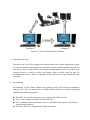
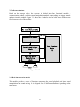
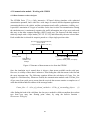
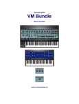
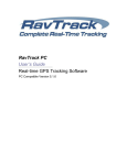
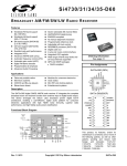
4) Utilization environments
At present, the utilization environment is the vehicle simulation room at Chalmers, instead of
implementing in a real vehicle. The equipment and their connectivity are shown in Figure 2.1.
1. The driving equipment: a driver’s seat and a control system including steering
wheel, pedals and shifter;
2. The visualization system that displays the traffic simulation, both LED screen or
projector are accepted;
3. Loudspeakers for playback of auditory icons;
4. Computer 1 running STISIM simulator software, which controls the driving
equipment and the screen and passes the traffic information data to Computer 2;
5. Computer 2 running the test software, which receives data from computer 1 and
plays the processed sounds using loudspeakers
6
2
1
Co
ntr
ol
Control
3
4
5
STISIM
Simulator
Desired
Software
Data Stream
Computer 1
Computer 2
Figure 2.1: Software Utilization Environments
5) Operational life circle
The thesis work is an effort to improve the testing method for in-vehicle information systems.
For now, the software only operates in a laboratory with the vehicle simulator, instead of a
real vehicle. However, in the future, if the concept of using auditory icons for in-vehicle early
warning system is verified as useful and feasible, further research could be done by
developing this software. Thus it is important for the software to be open-sourced and wellstructured.
6) Environments
Environments, in this context, address the operating system (OS) and the programming
language (PL). There are many choices available in the market, but a desired environment
should contain following properties:
OS and PL are well known to target users, requiring less effort to learn.
Easy to code, with the possibility to modify the code.
PL is commonly used so that the user can access the HELP from anywhere like internet,
technical support and etc.
OS and PL are easy to maintain and develop in the future.
7
2.2 Programming language
In order to fulfill the needs of the software, the programming language should have outstanding
properties concerning the computational speed, ease-of-coding, and flexibility for future
development. The most popular programming languages nowadays, like MATLAB, C++ and C#,
have been taken into consideration and passed through two feasibility tests to find out the most
suitable one.
The first test intended to examine the computational speed for real-time sound activation and
manipulation, which requires the programming language to be able to trigger a sound without
delay and manipulate pitch without distortion.
MATLAB is widely used as a signal processing tool and has a collection of built-in signal
processing functions, suitable for the sound manipulation. In the test, it is easy to trigger events
using MATLAB functions. However, pitch shifting is virtually impossible to implement, because
the built-in wave play function does not allow changing pitch during real-time playback.
To tackle this problem, the audio stream was cut into small clips. A user-defined function
applied a pitch shift filter to each sound clip in advance, while the previous clip was played back.
However, this method failed as well, because it was not fast enough to apply the filter before the
last playback, resulting in gaps between successive sound clips.
C++ is considered as the most powerful programming language, especially for real time
processing, and a third party application, ‘Csound’, was found to be useful. Also for C#, a third
library, called ‘NAudio’, was an open source .NET audio library, containing dozens of useful
audio related classes intended to improve audio related utilities in .NET. It has been in
development since 2001 and has grown to include a wide variety of features. It has basic
functions like audio playback, and also powerful audio mixing. Both C++ and C# had
extraordinary performance on the first feasibility test, which means these two languages were
compared further.
The second test was designed to find out the language’s capacity of handling multiple sounds.
Both C++ and C# worked perfectly with audio mixing. However, the biggest problem with C++
was that the Csound library was unable to communicate with STISIM. It needed an API
(Application Programming Interface) to transfer the data stream, and this API required a Linuxbased programming environment on Windows OS, which was hard to configure since Windows
7 had blocked such access.
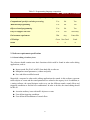
The detailed comparison among these three programming languages is shown in Table 2.1. It is
necessary to point out that GUI (Graphic User Interface) design is another important factor for
choosing C# over others. A variety of GUI components from C# has extraordinary performance
when it comes to multi-tasking, and is easy to learn and code as well.
8
Table 2.1 Programming language comparison
C#
MATLAB C++/Csound
Built-in functions or libraries concerning audio processing
Yes
Yes
Yes
Computational speed for real-time processing
Yes
No
Yes
Multi-thread programming
Yes
No
Yes
Object oriented programming
Yes
No
Yes
Easy to configure and code
Yes
Yes
Not really
Environment requirement
Win
Any
Linux like
GUI design
Great
Not Good
Good
O
X
X
Result
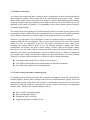
2.3 Software requirements specifications
2.3.1 Sound editing of auditory icons
The software should contain some basic functions which could be found in other audio editing
applications, such as:
Import sound file (WAV or MP3) from hard disk to software
Manipulate sound parameters ( volume and pitch)
Save and delete modified sounds
Meanwhile, compared to other audio editing applications the sounds in this software represent
traffic objects or events and the sound parameters are related to the urgency level. In addition, as
a testing software, the sound designer needs to try out the different sounds, sound effects and
triggering conditions to find the best combinations. In order to do this, the sound editing should
be able to:
Associate auditory icons with traffic objects or events
User-define triggering conditions
User-define the mechanisms of sound effects
9
2.3.2 Intuitive sound effects
As is known, the sounds with time-varying frequency contents deliver more information than the
static frequency contents. Three sound effects are implemented in the present work - volume
change of the sound, which would relate to the distance to objects; pitch shifting, which indicates
the speed of objects; and spatial panning, which helps the driver to locate the traffic objects. The
amplitude of the sound, for instance, is corresponding to the volume variation and its frequency
is related to pitch shifting.
The sound effects are not going to be fixed but depend on the user’s needs. In this context, effect
mechanisms become complex since the sound parameters are associated with traffic parameters
(speed, distance, direction, etc.) and the range of each sound parameter is also unknown.
Therefore, it is important to leave flexibilities to users to configure their own sound effects, by
setting up different effect mechanisms. There are two reasons for that. First, the traffic situation
differs over time, it is impossible to use one fixed effect mechanism for every single event.
Secondly, the testing software needs to try out different parameter settings and effects
combinations. For instance, the effect, volume change, could be related to the distance change
between two cars, but it also could be related to the relative speed. The Doppler Effect usually is
defined by the relative speed and distance, but the weights of these two factors are unknown.
Users might want to change the different weights of the speed and distance for a better solution.
Therefore, it is better for users themselves to define the effect working mechanism:
User defines what sound effect or effects to use in the test
User defines connection between sound parameters and traffic parameters
User defines the weight of each sound parameter
2.3.3 Traffic tracking and intuitive sound triggering
A warning system is not only activated when a critical event happens, but also able to predict the
potential dangers. Sensory data is passed to the processor which determines urgency levels and
corresponding actions. In this thesis, the software is considered as this processor. It receives the
data from the driving simulator, determines the current situation, and triggers the appropriate
auditory icons. Therefore, the software should be able to:
Receive traffic environment inputs.
Keep tracking traffic objects.
Examine the risk of collision.
Trigger the playback of auditory icons.
10
2.3.4 Graphical user interface and user controls
In the previous sections, the overall functionalities of the software were discussed. Its userdefined features provide flexibility for the end user but cause some challenges when designing
the user interface. Nowadays, the most commonly used user interface (UI) is the Graphical User
Interface (GUI). However, a good GUI is not that easy to design. If one considers the sound
settings for the auditory icons, the operations could not be accomplished by one or two clicks.
The lowest requirement for GUI would be an accepted usability that can guide users to
accomplish their tasks even without a user manual. In this context, the GUI should be able to:
Guide user how to set up test scenarios, imports sounds, defines sound effects, connects
with simulators, etc.
Make functional GUI components comprehensible by their appearance. For instance, a
button named “Play” indicates audio playback.
Give feedback whenever a user triggers an event, including the software status,
notifications, and error messages and so on.
Increase the efficiency of the software by reducing the number of inputs from the user as
much as possible.
Another aspect of the GUI design is the user’s ability to control the software during testing. One
solution to do this is restarting the test from the top, which is clearly not a good idea. An
alternative solution would be if users could disable it as soon as they can. Therefore, a GUI is a
good solution for real-time user controls, including:
Enabling and disabling sounds during the test
Applying and removing sound effects during the test
Modifying the effect parameters and weights during the test
2.3.5 Open structure for future development
Open structure is a universal requirement for software development. It means that the software
structure and codes should not constrain to the current requirement, but leave the access for new
plugins. In the software, there are three aspects needed to be extended in the future:
Adding new sound effects
Adding new sound effect parameters
Interface to other devices, like MIDI
11
12
Chapter 3
Software Design
3.1 Design concept
Since the software requirements were specified, the next step was planning a solution that
fulfilled all those requirements. The design concept was to identify the key problems from the
requirements and provide solutions to each one of them. In order to do so, it is important to look
at the test procedure as a whole and to see how the software fits into it. There are three stages to
perform a test.
Stage 1: Test preparation
Before the real test is started, the testers need to initialize both the hardware and the software,
especially this sound manipulation software. The tester selects the warning sounds and imports
them into the software, associates these sounds with traffic events, and also configures the
connection between the simulation software and this software.
Stage 2: Test run-up
During the test, the driver operates the driving equipment and hence interacts with the vehicle
simulator based on a 3D animation which is projected on a wall. The warning system consists of
two speakers and the sound manipulation software. In this stage, the only thing the tester needs
to do is to click the ‘Start’ button and then the warning system works automatically. However, a
real-time user control is needed so that the tester is able to change settings promptly in the case
that something goes wrong. For example, the testers can manipulate the mechanism of the sound
effect and also disable and enable traffic events during the test, if needed to test the particular
events and warning sounds.
Stage 3: Interview and questionnaires
In this stage, the tester discusses the opinions of the driver concerning the warning sounds by
asking the driver a list of questions. Thus, the software at this stage is believed to have fulfilled
its purpose. However, after each test, a historical log file should be created by the software that
records the detailed information about the test - start and end times of the test, the choice of
warning sounds, numbers of crashes, etc.
Therefore, the software should perform the following functions:
Sound playback
Sound manipulation
Receive and sift out environment inputs
Store and organize the input data
Act as a decision-making agent for sound activation
Incorporate a GUI to allow for better settings and control during the test
13
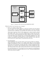
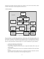
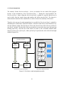
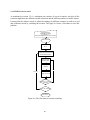
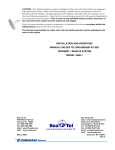
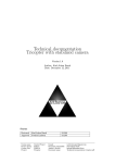
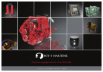
3.2 Software structure
Based on the concept above, the software is divided into four functional modules communication module, real-time sound manipulation module, and tracking and trigger module
and user interface module. Figure 3.1 shows the 4 modules and the bold arrows indicate data
flows between each of the modules.
Input:
Car sensor;Simulator;MIDI;
Testing Software
Communication module
User Interface
Module
(UI)
Tracking and Trigger
Module
Real Time Sound
Manipulation
module
Speakers
Figure 3.1: Software structure
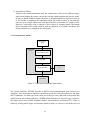
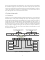
3.2.1 Real time processing module
This module provides a series of functions concerning the sound playback, real time sound
manipulation and sound mixing. It is designed for two different situations depending on the
target users:
14
Real time sound
manipulation
module
Import warning
sounds
User interface
Save or delete
warning sounds
Sound
manipulation
T&T module
Sound Player
(Mixer)
Figure 3.2: Structure of the real-time sound manipulation module
Within this module, three functional units are designed
1) Import, save or delete warning sounds
It is a unit which deals with the sound files. It imports the sound files from the hard disk
into the software, saves the modified warning sounds back to the disk, and deletes
unwanted sounds. In additional, it also transforms the sound files into a unique encoding
format (stereo sound wave with 44.1 kHz sampling rate), so that the software is able to
mix multiple sounds. There are too many encoding formats to choose from like MP3,
WAV and so on. In the present thesis, the software adopts the WAV format since it
retains more details of the sound than MP3. A relatively higher sampling rate (44.1 kHz)
is used. The Two-channel encoding enables the isolated manipulation on each of the
channels, thus helping the spatial panning of the sound. Therefore, all the sound files,
before being used as warning sounds, are transformed into this format.
2) Sound manipulation
Sound manipulation is the core of the software, and it can be used under two conditions –
during sound editing and during the test. During sound editing, the tester manually
modifies sound parameters to create a new sound. Hence the software provides flexibility
to the testers, in a way that they can change the pitch or volume by dragging track bars.
During the test, the software works automatically with the vehicle simulator. The trigger
and tracking module decides which warning sounds should be activated and passed into
the sound manipulation unit. The tracking process keeps passing the corresponding data
based on the sound effects settings that the tester has set up. The detailed implementation
will be shown in the next chapter.
15
3) Sound player (Mixer)
Similar to the sound manipulation unit, the sound player works in two different stages:
while sound editing, the testers can mix the selected sounds together and hear the result.
In order to handle multiple sounds, the mixer is designed that has the capacity to mix up
to 100 sounds. According to the simulation design, one traffic scenario, at one moment,
can have up to 4 traffic objects and each object can have a maximum of 3 traffic events.
Moreover, each traffic event is consists of one or up to 10 warning sounds. That meant
that a maximum of 40 sounds could be used for playback, at an instant, and hence 100
mixing channels were enough for the driving test.
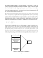
3.2.2 Communication module:
Environment
inputs
Communication
Module
Receive raw input data
Parse data
Sift out useful data
UI
T&T module
Figure 3.3: Structure of communication module
The vehicle simulator, STISIM, provides a RS232 serial communication port between two
computers. This means that an interface is needed to access the serial port and receive the input
data. Furthermore, the data type on the serial port is the byte array and needs to be parsed into
useable format, the floating-point array. STISIM defines that there are up to 50 types of data for
one single object, such as speed, longitude distance, lateral distance, acceleration, TTC (Time to
collision), steering wheel angles, acceleration caused by brake, etc. However, not all the received
16
data is used during the test. The software allows the tester to choose usable input parameters to
use and to relate them with traffic events.
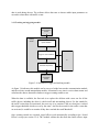
3.2.3 Tracking and triggering module:
Communication
module
Trigger &
Tracking
module
Update database
Trigger or cutoff conditions
UI
Parameter dependency
Real-time sound
manipulation
module
Figure 3.4: Structure of Trigger and tracking module
As figure 3.4 indicates, this module can be seen as a bridge between the communication module
and the real time sound manipulation module. It functions every time it receives data stream and
calculates the data to determine whether to trigger warning sounds or not.
When the data is available, the first task is to replace the old data with a new one for all the
traffic objects, including the driver’s vehicle itself and surrounding objects. For the sounds for
the traffic events that are inactivated, the next step is to examine if the new data have reached
their trigger threshold which were set by the tester. And for the sounds for the traffic events that
are activated, it would be to examine if they have reached the cutoff threshold.
Once warning sounds are activated, sound effects work automatically according to the ‘Sound
Effects’ set-ups (see section 3.2.4). T&T module collates the data from the chosen effects, input
17
parameters and weights, and then calculates the variation of each of the chosen effects, which
would be utilized by the sound manipulation module later on.
3.2.4 User interface
Import warning
sounds
User interface
Manul sound
manipulation
Assign warning
sounds to traffic
events
Save modified
warning sounds
Define trigger and
cutoff conditions
Feedback
information display
Communication
configuration
Associate tracked
objects with traffic
events
Communication
module
Parameter
dependency
settings
Start and Stop
the test
T&T module
Real-time sound
manipulation
module
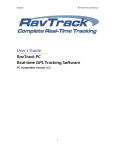
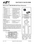
Figure 3.5: Structure of user interface module
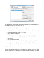
The user interface is a module that works directly with the tester, while other three modules work
behind stage. The main reason behind the tester using the GUI is to accomplish the testing setups, such as sound library, connections among different modules, initializing simulator scenario
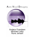
and so on. The main interface is shown in figure 3.6. It can be divided into five parts which are:
-
a window for displaying operation history;
three buttons to start, stop or exit the test;
a sound library settings that allows the tester to import and modify traffic events and
warning sounds;
a sound effects settings where the tester set up parameter dependency before and during
the test;
a simulator control that enables the tester to configure the simulator connection, associate
objects with the events and observe the data change during the test.
18
It is not necessary to follow this order but needs to perform all the actions in a given step.
Figure 3.6: Screen shot of the main interface of the software
(an example of ‘Vehicle approaching’)
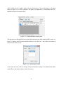
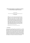
3.2.4.1 Sound Library
The sound library has a collection of a set of warning sounds that can be used for different events.
By clicking the button ‘Add’ or ‘Edit’, the figure 3.7 would show up and meanwhile the main
interface would be disabled.
19
Figure 3.7: Screen shot of Sound Editor
The functions in the interface enable the tester to: (see appendix I for information about GUI
components Combo box, List box, Text box, Check box)
-
-
Define the name of a traffic event.
Define the object type of event by choosing from the Combo Box.
Add, save and delete sound samples associated with the traffic event (associate warning
sounds with event).
Select sound samples at the List Box to edit or delete.
Rename the chosen sound sample.
Play the chosen sound sample.
Modify the chosen sound sample by dragging the ‘Track bar’ marked by Pitch and
Volume. To be more accurate, the Text box is placed beside of track bar for the tester to
enter numbers.
Save the modified sound sample
Enable the chosen sound sample to loop when playback, by marking the Check Box
marked ‘Loop’.
Set up trigger and cut-off conditions. An example is shown in figure 3.7. It indicates that
this traffic event arises when the relative distance is lower than 50 meters and ends when
the relative distance is lower than 10 meters.
3.2.4.2 Sound Effects setting
This step allows the tester to define how the sound effects work. The check boxes help to enable
or disable sound effects. The ‘Weight’ track bar indicates the degree of influence of the input
20
parameter on the sound effect. All these components can be real-time manipulated, which allows
the tester to change settings during the simulation.
3.2.4.3 Simulator settings
The simulator control has two simulator options. The custom simulator is designed for a pre-test.
That enables the testers to hear their sound designs and sound effects before the driver. There are
three traffic objects in total and their actions are set to approaching to the driver. The relative
distance decreases by the speed that the tester has chosen from combo box. The decreasing rate
is 0.1 second which means sound effects changes every time the distance decreases.
Compared to the customized simulator, STISIM simulator is harder to configure owing to its
complex scenario structure. One STISIM simulation is made of several scenario blocks; and each
block consists of multiple traffic objects which can be vehicle, motorcycle, and pedestrian and so
on. The blocks are segmented by the elapsed distance since the beginning of the run. For
example, taking 1000 meters as block stride, block 1 starts at 0 meter and ends with 1000 meters,
and block 2 starts at 1000 meters and finishes at 2000 meters, and the list goes on.
From the software perspective, the number of scenarios, total length of each scenario and the
number of objects within each scenario are required for the test initialization. Unfortunately,
none of that information can be found from the serial port that the STISIM provides. Hence,
some manual operations are needed. First, the tester creates scenario blocks by opening and
editing the ‘Scenario Editor’ (see figure 3.8). A block is created by enabling the corresponding
checkbox and specifying the length of the block by entering the ending length in the text box .
Figure 3.8: Screen shot of STISIM scenario editor
21
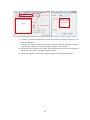
After clicking on the ‘Confirm’ button, the selected number of tabs would appear on the main
form (see figure 3.9). A GUI component ‘Tab group’ (see appendix I) is created and each ‘Tab’
indicates one specific scenario block.
Figure 3.9: STISIM simulator control panel
The next step is to add traffic objects to each block and associate them with the traffic events. As
figure 3.10 shows, traffic events would be listed on ‘List Check box’. One object can consist of
more than one traffic events.
Figure 3.10: Tracked object editor
At run time, the tester is able to change effects and simulator settings. It can disable and enable
sound effects, and mute an object sound if necessary.
22
3.3 Data structure
The data structure addresses the question of storing and organizing data so that it can be used
efficiently. In the present thesis, the data structure needs to store the data from the simulator, to
assign trigger and cut-off conditions and to associate them with intuitive warning sounds.
At first, an object-based model was designed so that the traffic object was the basic data unit of
the software. Each traffic object had its own database to save the STISIM data, trigger and cutoff conditions, and a set of warning sounds. By doing so, when a certain traffic object entered the
critical zone, its assigned warning sounds would be produced to inform the driver. However, the
flaws of this data type were that the traffic object’s behaviors differed over time and it was
impossible to use one group of sounds to represent. The testers might want to use different
sounds to represent different situation, like the sound of a car tire skidding to indicate the
proximity to a leading car, sound a crash to indicate collision. Therefore, an event-based data
type was created. This data structure focuses on the particular actions that the traffic object
makes.
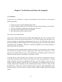
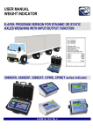
The design of the data structure corresponds to the structure of STISIM scenario and event-based
data model, which can be arranged by following logic:
-
STISIM scenario consists of scenario blocks
One block is made of traffic objects
Each object might have numbers of events
Each event is represented by a set of auditory icons
There is no limit on the number of objects, events and sounds
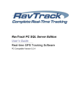
Therefore, 4 class1 objects are created and nested together, shown in figure 3.11. The direction of
the arrow means that the class object on the right is a subset of the class on the left. The class
‘ScenarioBlock’ , for instance, includes a group of class object ‘TrackedObject’.
Note: This figure only shows data members of a certain class object, not class methods.
1 In object-oriented programming, a class is a construct that is used to create instances of itself – referred to as class instances, class objects,
instance objects or simply objects. A class defines constituent members which enable its instances to have state and behavior. Data field members
(member variables or instance variables) enable a class instance to maintain state. Other kinds of members, especially methods, enable the
behavior of class instances. Classes define the type of their instances. (See http://en.wikipedia.org/wiki/Class_%28computer_programming%29)
23
Scenario Block
List<>(TrackedObject)
Start_Distance
Block_Range
TrackedObject
SampleSet
List<>(SampleSet)
Object_Type
Data_Speed
Data_Distance
Data_Position
Data_CollisionTime
IsMuted
List<>(SampleGraph)
Event_Name
Object_Type
Thres_Trigger
Thres_Cutoff
SampleGraph
Source_Stream
Effect_List
Effect_Stream
IsLooped
Figure 3.11: Relationship between sound and STISIM driving Scenario
The class ‘SampleGraph’ holds the original data source of the warning sound and creates
‘Effect_Stream’ data type which combines the original sound with the sound effects. The
‘SampleSet’ is the class object that defines the traffic event and its activation conditions. The
‘TrackedObject’ corresponds to a certain traffic object and is used for saving the input data.
24
Chapter 4
Implementation
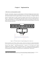
4.1 Real-time sound manipulation module
The forms of file formats, compression, and data storage of sound are all changing since the past, but the
underlying mechanisms for playback and manipulation have not varied much. The digital audio playback
unit reads the sound file into the computer memory in the forms of byte array. An example of the data
structure of digital sound wave which is encoded in a standard 16-bit 44.1 kHz stereo format is shown in
figure 4.1. Sound wave is encoded alternately, which means the bytes of respective channels alternate in
a single stream (LRLRLR, etc.). The DAC (Digital Analog Convertor) can recognize the structure of the
audio stream and convert them into analog signals and split them into different channels, and then that
sound is presented to the listener.
2 bytes = 16 bits
1
0
1
0
1
1
1
1
0
Left channel
1
0
1
0
1
1
1
Right channel
One
sampling
point
Figure 4.1: The data structure of a single sampling point of sound wave
In the present thesis, the C# library NAduio provides a collection of functions for digital sound playback
[6]. It reads the sound file by creating the NAduio.WaveStream class and simply plays this audio stream
using the class method 2 - NAduio.WaveStream.Play( ). However, it is not that easy for sound
manipulation since the binary numbers in which the sound wave is encoded cannot directly be modified
and there is no existing function for manipulation. The next section would discuss the implementation of
sound manipulation by creating a new class EffectStream, an inherited class of WaveStream.
2
Method, in object-oriented programming, is a subroutine (or procedure) associated with a class. Methods define the behavior to be exhibited
byinstances of the associated class at program run time. (see: http://en.wikipedia.org/wiki/Method_(computer_programming))
25
4.1.1 Sound manipulation
The method, NAudio.WaveStream.Read( ), leaves an interface for the sound effect plug-ins
because of the mechanism of the WaveStream.Play( ). During the sound playback, the
WaveStream.Play( ) keeps calling the WaveStream.Read( ) method at a specific interval rate to
read a buffer from the sound stream and transfers this buffer into the DAC. The interval is
shorter than the duration of the sound buffer, in order to ensure the continuity of the sound.
Therefore, the concept of sound manipulation is to modify the WaveStream.Read( ) method by
embedding the sound effects within this method, so that the sound effects would function every
time the method is called. The EffectStream Class is the derived class of WaveStream, and has its
own Read( ) method. The first task of this new method is to convert the byte array data type into
floating point array. And then the sound effects are done by the overridden method called
Sample(ref float spl0, ref float spl1), where spl0 and spl1 represents the value of the left and right
channels respectively.
Sound files(*.WAV*.MP3)
Convert byte[] into
float[]
EffectWave.Read(Buffer[],BufferSize)
Create
EffectStream
WaveStream.Read(Buffer[],BufferSize)
Create
WaveStream
EffectStream.Read( )
DAC
&
Speaker
Modified
EffectStream
Buffer
Effect:
Volume
Change
Effect:
Pitch Shift
Effect:
Panning
Convert float[]
back to byte[]
(a) Mechanism of digital audio playback
(b) Flowchat of EffectStream.Read()
Figure 4.2: Real-time sound manipulation module
26
The word ‘overridden’ means that this method allows the subclass to provide a specific method
implementation. In other words, the subclasses can implement different functions by coding the
same method, while they share the other features from the parent class. It allows the usage of one
Effect class framework to create different sound effects by modifying the specific methods.
EffectStream
List<>(Effect)
WaveStream
Read()
Play()
...
Effect:Volume
Effect:PitchShift
Effect:Panning
Block()
Sample()
Slider()
...
Block()
Sample()
Slider()
...
Block()
Sample()
Slider()
...
Figure 4.3: The data structure of the class EffectStream and Effect
The figure 4.3 indicates that the EffectStream consists of a list of sound effects, which
individually is represented by creating different subclasses of Effect (Volume, PitchShift, and
Panning). Each effect has its own Block() and Sample() method. For example, to lower the
volume by 50%, the method Volume.Sample() could be coded as follows:
public override void Sample(ref float spl0, ref float spl1)
{
spl0 *= 0.5f;
spl1 *= 0.5f;
}
4.1.2 Sound mixing
In order to handle multiple sounds, a player was needed that was capable of mixing all the
warning sounds, which could be done by the class - NAudio.Mixer. The method Mixer.Init( )
initializes a certain amount of mixer’s channels (Mixer.Wavechannel class) and each of the
channels holds an EffectStream. Adding a new EffectStream to the mixer or removing one from
the
mixer
is
done
by
using
the
methods
Mixer.AddInputStream()
and
Mixer.RemoveInputStream(). However, the problem was that these two methods restricted the
use of the mixer. The length of the mixer is fixed when adding the first sound stream, and the
mixer would stop working when it reached the end of the stream. In simpler words, the sounds
could not be played back when the first sound stream ends. Therefore, the AddInputStream( ) and
RemoveInputStream( ) methods were unsuitable for the sound activation.
27
An alternative method was found by using class members of WaveChannel - Volume and
Position. WaveChannel.Volume allows the mixer to modify the volume of each of the mixer
channels individually. WaveChannel.Position indicates the current playback status of each of the
mixer channels. For example, if WaveChannel.Volume is set to 0, the corresponding
WaveChannel would be silence. And if WaveChannel.Position is set to 0, it means the mixer will
play the certain channel from the first stream buffer.
The principle of the sound activation is simply to unmute and mute warning sounds in an audio
mixer. As the tester has set up the traffic events completely and start the test, all the warning
sounds are initially mixed together and set to silence. By doing so, each of the sounds is assigned
an address of mixer channels. Once the assigned sound is activated for a traffic event, the
corresponding mixer channel is unmated. In opposite, the cut-off function is to mute related
sounds again. An example below shows that the 10th sound stream in WaveChannel is activated.
WaveChannel[10].Volume = 1;
WaveChannel[10].Position = 0;
To ensure that the length of the mixer was sufficient enough to support the simulation test, a
silence BaseStream with a long duration was created so that the mixer worked until the test
finishes. Normally, the duration of one simulation scenario ranges from several minutes to half
hour, depending on the performance of the driver who operates the vehicle simulator. If the
driver drives slower than the average speed that the tester has designed, the duration would last
longer than expected time but no more than 30 minutes owing to the time limitation of the
scenario design used in the previous test. Therefore, the length of BaseStream is set up to 1 hour.
WaveChannel[0]
BaseStream
WaveChannel[1]
Effectstream
WaveChannel[2]
Effectstream
Mixer
.
.
.
WaveChannel[n]
Effectstream
Figure 4.4: Channel structure of mixing player
28
4.2 Communication module - Working with STISIM
4.2.1 Data Structure on the serial port
The STISIM Drive [7] is a fully interactive, PC-based driving simulator with unlimited
customization potential, and is ideal for a wide range of research and development applications
concerning the driver, the vehicle, and the environment (road, traffic, pedestrians, visibility, etc.).
It provides a maximum of 50 types of variables for the user to select for communication. During
the simulation run, it continuously organizes the traffic information into a byte array and sends
this array to the other computer through a RS232 serial port. The format of the data stream is
relatively simple with a 4 byte header [255 255 255 255] and followed by the user-selected data.
Each variable that is selected for output is passed as a 4 byte single precision value.
Up to 50 types of information about the
driver’s veihcle
(Longtitude speed, Distance, TTC, etc.)
255 255 255 255
1 bytes
4 bytes
…….
Message Header
4 bytes
4 bytes
4 bytes
3 types of information about the surrounding
traffic object
(Distance, Lateral position, and Speed)
Total number of
variables in this
message
Figure 4.5 Structure of data stream receive from the STISIM
Once the simulation test is started, there is always a data stream available on the serial port.
However, its validity of those data is unknown. Thus finding the valid data stream is the first and
the most important step. The following equation defines the calculation of Frame_Size, the
length of a valid data array. Whenever needed, the communication module reads 2*Frame_Size
of byte array from serial port to ensure that the received data stream contains a complete set of
valid data and then finds the address of the message header.
Frame_Size = 5 + 4*nr_of_selected_varibales + 4*3*nr_of_surrounding_objects
(1)
After finding the head of the valid data, the data parse method is called to transform the raw data
type from byte array into floating point values, by using the built-in function –
bitconvertor.ToSingle().
29
4.2.2 STISIM scenario switch
As mentioned in section 3.2.4, a simulation run consists of several scenarios, and each of the
scenarios might have the different variable selections and the different numbers of traffic objects.
It means that the software needs to adjust the settings for different scenarios in order to avoid
data collisions caused by switching the scenario. The figure 4.6 shows a flowchart to solve this
problem.
The tester sets up
Scenario[Nr_Scenario]
Nr_Scenario = ?
Add TrackedObjects to each of the scenario
Start the test
N=0
Initialize the Nth of scenario
(Create new mixer and put all
the sounds into mixer)
Receive Inputs
and parse data
Tracking
No
No (N++)
Trigger and Cutoff
Is Escaped
distance >= Length
of scenario
Yes
Is N = Nr_Scenario
Yes
End the test
Figure 4.6: The flowchart of scenario switching
30
The key point of this solution is the initialization of a new scenario. Once the escaped distance
has exceeded the length of the current scenario, the software would release the currently used
scenario, mixer and tracked objects, and then start the next scenario. Initialization of a scenario is
a process that combines the complete set of sound samples of all the tracked objects into the
mixer, and assigns the value 0 to each of WaveChannel.Volume.
4.3 Tracking and trigger module
4.3.1 Tracking process
Tracking is a process of updating information of all the tracked objects in a given scenario that
includes the driver’s vehicle and the surrounding traffic objects. The tracking processing does
not only transfers the parsed data into corresponding objects, but also calculates several types of
variables that reflect the relationship between a certain surrounding object and the driver. An
example is shown in figure 4.7, where only one traffic object exists in scenario besides the driver.
The value of Object1.TTC with respect to the Driver could not be acquired from parsed data
array, but could be calculated by knowing the value of the Distance and Speed of both Driver
and Object1. Similar to TTC, the value of relative speed, distance, acceleration and so on, could
be acquired by the same means.
Up to 50 types of information about the
driver’s veihcle
(Longtitude speed, Distance, TTC, etc.)
255 255 255 255 1 bytes
…….
4 bytes
3 types of information about the surrounding
traffic object
(Distance, Lateral position, and Speed)
4 bytes
4 bytes
4 bytes
Data parse
20.0f
100.0f
0.0f
…….
30.0f
50.0f
0.0f
TrackedObject:
Driver
TrackedObject:
Object1
Speed
Speed
Distance
Distance
Position
…….
Position
(Driver.Distance – Object1.Distance)/
(Driver.Speed – Object1.Speed)
TTC
…...
Scenario 1
Figure 4.7: An example of tracking process
31
4.3.2 Trigger process
One tracked object can have several sets of sound samples associated with that particular event.
The triggering process checks triggering conditions for each sound sample set. Figure 4.8 shows
the complete flow chart for the triggering processing.
Tracked Objects
Updated
Take first Tracked
Object in Scenario
Take first Sample
Set in Tracked
Object
Is Triggered?
No
Yes
Cutoff
Condition?
Trigger
Condition?
Yes
No
Sound Effects to
Process
ToActive
(this.sampleset)
No
No
ToCutoff
(this.sampleset)
Move to Next
Sample Set in
Tracked Object
No
Sample Set =
Null ?
Yes
Move to Next
Tracked Object in
Scenario
Tracked Object
= Null ?
End update
Back to Data
prase
Figure 4.8: Flowchart of trigger process
32
To simply the sound activation, the trigger and cutoff conditions simply depend on one of input
parameters - Distance, Speed, Time to Collision, and Position. Two Boolean variables,
IsTriggered and IsCutoffed, are designed as the flags to prevent from redundant activation. As
long as the warning sound is triggered, the value of IsTriggered is set to True. It means that the
trigger process will not examine the trigger condition for this sound track but will examine only
the cutoff condition, so that one warning sound of certain traffic event is activated only once.
33
34
Chapter 5 Verification and Future Development
5.1 Verification
Several tests were conducted to evaluate the performance of the software by answering the
following questions:
1.
2.
3.
4.
5.
Is there any latency when manipulating the sound?
Does the sound activation work? And is there any delay when the trigger event is called?
Are the sound effects considered to be intuitive by the driver?
How many sound channels can the mixer handle?
How many objects can the software track?
The answers are mentioned below:
There were no delays with the sound activation and manipulation. However, the quality of the
sound effects was relatively poorer than expected. The Volume Change effect indeed gave the
driver the feelings of approaching and departing of the objects. The Pitch Shift effect worked
perfectly but hardly created the Doppler Effect. The hearing experience was better with binaural
reproduction using headphones. Therefore, an advanced algorithm for the spatial panning is
needed in the future development.
The intuitiveness of the warning sounds is subject to the driver’s own experience. Some of them
can easily tell the meanings of each warning sound, while others do not. However, it is the
purpose of the software that not to give a best solution but to test different types of sounds and
sound effects and to improve the auditory icon designs over time.
To test the tolerance of the software, Up to 20 objects were used in one scenario block, and each
of the objects associated with 3 traffic events, where one event was represented by 3 warning
sounds. Therefore, the heaviest workload for the mixer was 180 channels in one test run. It
turned out that the software worked really well, even though it was annoying to have so many
warning sounds around. Normally, the tester would design a scenario with 2 to 4 objects so that
the performance of the driver related to different objects would be easily distinguished at the
final data analysis. Thus the software is capable enough to handle multiple objects and warning
sounds.
35
5.2 Discussion and future Work
The testing software provides a foundation for HMI researcher and sound designer to work with
the vehicle simulator – STISIM and to evaluate the in-vehicle information systems. Even though
it can satisfy the needs of the current testing scenario, it can be improved in following aspects.
1) Better sound activation
Trigger event must be improved in the future. For now, the software adopts a very simple
trigger rule, which cannot satisfy all the traffic situations. The next step is to make the
software smarter. It can determine whether the situation is urgent or not, set different
priority to the traffic events. If several events happen at the same time, it should trigger
the most dangerous one. It means that the software should have a decision making unit,
where the trigger and cutoff conditions are not only related to one parameter, but
combination of parameters based on the understanding of the current traffic situation. It is
very complicated mission but necessary.
2) Better sound effects
The sound effects are the essence to make the sound intuitive. The Panning effect, in the
present thesis, needs to be improved to work with the loud speakers. And also the Pitch
Shift effect could be improved by implementing a more advanced algorithm.
Another improvement could be increasing the parameter dependency of the sound effects.
The volume effect now has one parameter dependency which is the relative distance. But,
in the future, there might be using the combination of distance and speed for this effect.
Of course, the last improvement can be made by adding new sound effects.
3) Better user interface
In the present thesis, leaving flexibility to the user has made the software so many set-ups
that the user spends too much time on the test settings rather than running the test. In
some cases, configuring STISIM scenario, each object will be associated with sound
event. In one test run, there will be 5 to 6 scenarios and up to 20 objects within each
scenario, which means that the same operation repeats over 100 times to complete only
one function - adding new objects. Not to forget that if the tester makes mistakes when
running a simulation, they are going to re-do the set-ups all over again. To solve this
problem, the software must optimize the setting steps or provide a default setting, so that
the tester does not need to do the setting every time when opening the software.
36
References
[1] Horrey, W.J. & Wickens, C.D. (2002). Driving and side task performance: The effects of display
clutter, separation, and modality (Technical Report No. AHFD-02-13/GM-02-2). Savoy, IL:
University of Illinois, Aviation Human Factors Division.
[2] Ho, C. and Spence, C. 2005. Assessing the Effectiveness of Various Auditory Cues in
Capturing a Driver’s Visual Attention. Journal of Experimental Psychology: Vol. 11, No. 3, 157–
174
[3] Edworth, J. et. al. 1995. Design urgency into auditory warnings using pitch, speed and
loudness. IEEE COMPUTING & CONTROL ENGINEERING JOURNAL
[4] D. McKeown, S. Isherwood 2007, AUDITORY SIGNS TO SUPPORT TRAFFI
AWARENESS.
[5] Gaver. W.W. (1986). Auditory icons: Using sound in computer interfaces. Human-computer
Interaction, 2(2), 167-177.
[6] Mark Health, Skype Voice Changer. http://channel9.msdn.com/coding4fun/articles/SkypeVoice-Changer
[7] STISIM Driver, STI Co. http://www.stisimdrive.com/
[8] Interaction Design: Beyond human computer interaction, chapter 1
[9] A Stevens, 2000, Safety of driver interaction with in-vehicle information systems,
Proceedings of the Institution of Mechanical Engineers, Part D: Journal of Automobile
Engineering 2000 214: 639
[10] Laplante, Phil (2009). Requirements Engineering for Software and Systems (1st ed.).
Redmond, WA: CRC Press. ISBN 1-42006-467-3.
[11] John D. Lee, Brent Caven, Steven Haake, Timothy L. Brown, Speech-based Interaction
with In-vehicle Computers: The Effect of Speech-based E-mail on Drivers’ Attention to the
Roadway, Cognitive Systems Laboratory, University of Iowa, Department of Industrial
Engineering
[12] Jannette Maciei, Mark Vollrath, Comparison of manual vs. speech-based interaction with invehicle information systems, Prevention, Volume, September 2009, Pages 924–930
[13] Walt Scacchi, Process Models in Software Engineering, Institute for Software Research,
University of California, Irvine, February 2001
[14] Dingler. T., Lindsay. J., & Walker. B. (2008). Learnability of sound cues for environmental
features: auditory icons, earcons, spearcons and speech. Proceedings of ICAD 2008, Paris.
[15] Fagerlönn, J., & Alm. H. (2009). Auditory signs to support traffic awareness. Proceedings of
the 16th World Congress on Intelligent Transport Systems, Stockholm.
37
[16] Leung, Y.K., Smith. S., Parker. S., & Martin. R. (1997). Learning and Retention of Auditory
Warnings. Proceedings of ICAD 1997, Paolo Alto.
[17] Chen. F., Qvint. G., & Jarlengrip. J. (2007). Listen! There are other road users close to you
improve the traffic awareness of truck drivers. In C. Stephanidis (Ed.), Universal Access in
Human Computer Interaction. Ambient Interaction (pp. 323-329). Heidelberg: Springer.
[18] Graham. R. (1999). Use of auditory icons as emergency warnings: evaluation within a
vehicle collision avoidance application. Ergonomics, 42(9), 1233-1248.
[19] Belz. S.M., Robinson. G.S., & Casali. J.G. (1999). A new class of auditory warning signals
for complex systems: auditory icons. Human Factors, 41(4), 608-618.
[20] Tilman Dingler, Jeffrey Lindsay, Bruce N. Walker, 2008, LEARNABILTIY OF SOUND CUES
FOR ENVIRONMENTAL FEATURES: AUDITORY ICONS, EARCONS, SPEARCONS, AND
SPEECH, Proceedings of the 14th International Conference on Auditory Display, Paris, France
38
Appendix I GUI controls in C#
Button
Check Box
Track Bar
Combo Box
Radio Button
Tab Control
Data Grid View
1. Button: Raise an event when the user clicks it
2. Check Box: Enables the user to select or clear the associated option
3. Track Bar: enables the user to choose between a range of value by sliding a small bar
along on another bar
4. Combo Box: is a drop-down list of items from which the user can make a selection either
by clicking an item in the list or by typing into a box.
5. Radio Button: enables the user to select a single option from a group of choices when
paired with other radio buttons.
6. Tab control: manages and displays to the user a related collection of tabs that can contain
controls and components.
7. Data Grid View: displays rows and columns of data in a grid that the user can customize.
39
Group box
Text box
Checked list box
List box
8. Textbox: is a control in which the user inputs data from the keyboard. This area also can
display information.
9. List box: is a control in which a list of items is displayed. The user can make a selection
from the list by clicking on any item. Multiple elements can be selected.
10. Checked list box: displays a list of items with a check box on the left side of each item so
that the user can choose or clear the associated option.
11. Group box: displays a frame around a group of controls with an optional capture.
40
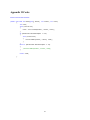
Appendix II Codes
Effectstream Read method:
public override int Read(byte[] buffer, int offset, int count)
{
int read;
lock (sourceLock)
{
read = source.Read(buffer, offset, count);
}
if (WaveFormat.BitsPerSample == 16)
{
lock (effectLock)
{
Process16Bit(buffer, offset, read);
}
}
else if (WaveFormat.BitsPerSample == 32)
{
//Process32Bit(buffer, offset, read);
}
return read;
}
41
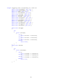
Effectstream method for sample level manipulation
private void Process16Bit(byte[] buffer, int offset, int count)
{
int samples = count / 2;
foreach (Effect effect in effects)
{
if (effect.Enabled)
{
effect.Block(samples);
}
}
for (int sample = 0; sample < samples; sample++)
{
// get the sample(s)
int x = offset + sample * 2;
short sample16Left = BitConverter.ToInt16(buffer, x);
short sample16Right = sample16Left;
if (WaveFormat.Channels == 2)
{
sample16Right = BitConverter.ToInt16(buffer, x + 2);
sample++;
}
// run these samples through the effect
float sample64Left = sample16Left / 32768.0f;
float sample64Right = sample16Right / 32768.0f;
foreach (Effect effect in effects)
{
if (effect.Enabled)
{
effect.Sample(ref sample64Left, ref sample64Right);
}
}
//Debug.Assert(Math.Abs(sample64Left) <= 1.0);
//Debug.Assert(Math.Abs(sample64Right) <= 1.0);
sample16Left = (short)(sample64Left * 32768.0f);
sample16Right = (short)(sample64Right * 32768.0f);
// put them back
buffer[x] = (byte)(sample16Left & 0xFF);
buffer[x + 1] = (byte)((sample16Left >> 8) & 0xFF);
/*byte[] b = BitConverter.GetBytes(sample16Left);
Debug.Assert(b[0] == buffer[x], "DOH");
Debug.Assert(b[1] == buffer[x+1], "DUH");*/
if (WaveFormat.Channels == 2)
{
buffer[x + 2] = (byte)(sample16Right & 0xFF);
buffer[x + 3] = (byte)((sample16Right >> 8) & 0xFF);
}
}
}
42
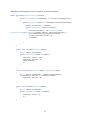
#region triggering event corresponding to a sound set
public
public
public
public
string EventName { get; set; }
string ObjectName { get; set; }
int Index { get; set; }
int channelIndex{ get; set;}
public
public
public
public
float StartVar { get; set; }
int StartIndex { get; set; }
int StartOpt { get; set; }
float StartThres { get; set; }
public
public
public
public
float CutoffVar { get; set; }
int CutoffIndex { get; set; }
int CutoffOpt { get; set; }
float CutoffThres { get; set; }
public bool IsTriggered { get; set; }
public bool IsCutoffed { get; set; }
public bool ToTrigger
{
get
{
switch (StartOpt)
{
case 0:
return StartVar <= StartThres;
case 1:
return StartVar >= StartThres;
case 2:
return StartVar == StartThres;
default:
return false;
}
}
}
public bool ToCutoff
{
get
{
switch (CutoffOpt)
{
case 0:
return CutoffVar <= CutoffThres;
case 1:
return CutoffVar >= CutoffThres;
case 2:
;
return CutoffVar == CutoffThres;
default:
return true;
}
}
}
43
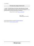
Audio Mixer: Initialize Mixer, to active a sound set, to cut off a sound set
public void Init(SimulatorScenario scenario)
{
foreach (TrackedObject trackedObject in scenario.TrackedObjectList)
{
foreach (SampleSet samples in trackedObject.SelectedSoundTracks)
{
samples.channelIndex = channelNo;
foreach (SampleGraph sample in samples)
{
channels[channelNo] = new WaveChannel32(new
WaveOffsetStream(new EffectStream(sample.Effects, sample.SourceStream)));
Mixer.AddInputStream(channels[channelNo]);
channels[channelNo].Volume = 0;
channelNo++;
}
}
}
}
public void ToActive(SampleSet samples)
{
int i = samples.channelIndex;
foreach (SampleGraph sample in samples)
{
channels[i].Volume = 1.0f;
channels[i].Position = 0;
sample.Rewind();
i++;
}
}
public void ToLoop(SampleSet samples, SampleGraph sample)
{
int i = samples.channelIndex + samples.IndexOf(sample);
if (channels[i].Position >= channels[i].Length)
channels[i].Position = 0;
}
public void ToCutoff(SampleSet samples)
{
int i = samples.channelIndex;
foreach (SampleGraph sample in samples)
{
channels[i].Volume = 0;
i++;
}
}
44
STISIM data parse and tracking code
private void port_DataReceived(object sender, SerialDataReceivedEventArgs e)
{
// read two size of byte buffer from port data stream
if (port.BytesToRead >= 2*frame_size)
{
byte[] bytes = new byte[2 * frame_size];
port.Read(bytes, 0, 2 * frame_size);
port_DataParse(bytes);
}
}
private void port_DataParse(byte[] bytes)
{
int offset = 0;
int stride = 4;
bool protector = false;
//List<float[]> input = new List<float[]>();
// find message header [255,255,255,255]
for (int i = 0; i < 2 * frame_size; i++)
{
if (bytes[i] == 255 && bytes[i + 1] == 255 && bytes[i + 2] == 255
&& bytes[i + 3] == 255)
{
offset = i;
protector = true;
break;
}
}
//useful data followed by header, now transfer byte data stream to
float array
if (protector)
{
int cnt = bytes[offset + stride];
float[] floats = new float[cnt];
for (int j = 0; j < cnt; j++)
{
floats[j] = (float)Math.Round(BitConverter.ToSingle(bytes,
offset + (j + 1) * stride + 1),2);
}
driver.Speed = floats[0];
driver.Distance = floats[1];
int k = 0;
protector = false;
}
}
45