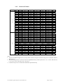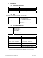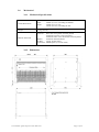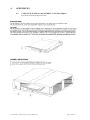
1
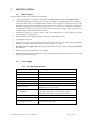
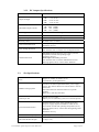
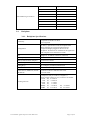
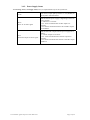
USER MANUAL AGILENT ACQIRIS 21-SLOT CPCI CRATE Manual Part Number U1092-90019 Edition D-RevB, June 2010 The information in this document is subject to change without notice and may not be construed in any way as a commitment by Agilent Technologies, Inc. While Agilent makes every effort to ensure the accuracy and contents of the document it assumes no responsibility for any errors that may appear. All software described in the document is furnished under license. The software may only be used and copied in accordance with the terms of license. Instrumentation firmware is thoroughly tested and thought to be functional but it is supplied “as is” with no warranty for specified performance. No responsibility is assumed for the use or the reliability of software, firmware or any equipment that is not supplied by Agilent or its affiliated companies. You can download the latest version of this manual from http://www.agilent.com/ by clicking on Manuals in the Technical Support section and then entering a model number. You can also visit our web site at http://www.agilent.com/find/acqiris. At Agilent we appreciate and encourage customer input. If you have a suggestion related to the content of this manual or the presentation of information, please contact your local Agilent Acqiris product line representative or the dedicated Agilent Acqiris Technical Support ([email protected]). Acqiris Product Line Information USA (800) 829-4444 Asia - Pacific 61 3 9210 2890 Europe 41 (22) 884 32 90 © Copyright Agilent 2010 User Manual: Agilent Acqiris 21-slot cPCI Crate Page 2 of 19 CONTENTS 1. OUT OF THE BOX ............................................................................................................. 4 1.1. Message to the User ...................................................................................................... 4 1.2. Before Using Your Crate............................................................................................... 4 1.3. Organization of This Manual......................................................................................... 4 1.4. Conventions Used in This Manual ................................................................................ 4 1.5. Disclaimer and Safety ................................................................................................... 4 1.6. Warning Regarding Medical Use .................................................................................. 5 1.7. Packaging and Handling................................................................................................ 5 1.8. Optional Equipment ...................................................................................................... 6 1.8.1. CompactPCI 6U to 3U Slot Adapter........................................................................ 6 1.8.2. Filler Plug-in............................................................................................................ 6 1.9. Warranty........................................................................................................................ 6 1.10. Warranty and Repair Return Procedure, Assistance and Support ................................. 6 1.11. Transport & Shipping.................................................................................................... 7 1.12. Maintenance .................................................................................................................. 7 1.13. Cleaning ........................................................................................................................ 7 1.14. Disposal and Recycling ................................................................................................. 7 2. INSTALLATION................................................................................................................. 8 2.1. Configuration ................................................................................................................ 8 2.2. Site Considerations........................................................................................................ 9 2.3. AC Mains Power ........................................................................................................... 9 2.3.1. Connecting to AC Mains Power .............................................................................. 9 2.3.2. Fuses ........................................................................................................................ 9 2.4. Installing CompactPCI Modules ................................................................................... 9 2.4.1. Installing 6U modules.............................................................................................. 9 2.4.2. Installing 3U modules............................................................................................ 10 2.4.3. Installing Filler Plug-in.......................................................................................... 10 3. SPECIFICATIONS ........................................................................................................... 11 3.1. Main Features.............................................................................................................. 11 3.2. Power Supply .............................................................................................................. 11 3.2.1. AC Input Specifications......................................................................................... 11 3.2.2. DC Outputs Specifications..................................................................................... 12 3.3. Slot Specifications....................................................................................................... 12 3.4. Backplane .................................................................................................................... 13 3.4.1. Backplane Specifications....................................................................................... 13 3.4.2. Power Supply Status .............................................................................................. 14 3.4.3. Connector Pinouts.................................................................................................. 15 3.5. Environmental ............................................................................................................. 16 3.5.1. Environmental Specifications ................................................................................ 16 3.5.2. Safety..................................................................................................................... 16 3.5.3. EMC Immunity & Emissions ................................................................................ 16 3.6. Mechanical .................................................................................................................. 17 3.6.1. Mechanical Specifications ..................................................................................... 17 3.6.2. Dimensions ............................................................................................................ 17 4. APPENDICES.................................................................................................................... 18 4.1. U1092A-C01 (U1056A-A10) XC100 6U to 3U Slot Adapter .................................... 18 4.2. U1092A-C02 (U1056A-A11) XC200 6U Filler Plug-in ............................................. 19 User Manual: Agilent Acqiris 21-slot cPCI Crate Page 3 of 19 1. OUT OF THE BOX 1.1. Message to the User Congratulations on having purchased an Agilent Technologies Acqiris product. U1091AC21, CC121 21-slot 6U crates use the highest quality components and high output power supplies in order to maximize system performance and reliability. These universally applicable CompactPCI crates are carefully designed to yield high performance test systems for bench, lab and manufacturing test applications. 1.2. Before Using Your Crate This User Manual describes the features of the CC121 crate and contains information for your safety, about configuring the crate, installing the modules, and operating the system. CAUTION 1.3. The AC power input line is fully protected by two fuses the value of which depends on the AC input voltage. For safety reasons, the user must check that those values comply with the input voltage used before connecting the crate to the AC mains power. For further information, please refer to the paragraph 2.3.2. Fuses. Organization of This Manual This manual is organized as follows : Chapter 1 OUT OF THE BOX, gives information you must know prior to using CC121 crates, lists the contents of the box, lists optional equipment you can order from us, and describes the warranty and repair return procedure. Chapter 2 INSTALLATION, describes how to prepare and operate your CC121 crate. Chapter 3 SPECIFICATIONS, gives complete technical specifications of your CC121 crate. Chapter 4 APPENDICES, gives specifications and assembly instructions supplied with the optional equipments. 1.4. Conventions Used in This Manual The following conventions are used in this manual : This icon to the left of text warns that an important point must be observed. WARNING Denotes a warning, which advises you of precautions to take to avoid being electrically shocked. CAUTION Denotes a caution, which advises you of precautions to take to avoid electrical, mechanical, or operational damages. NOTE Denotes a note, which alerts you to important information. Italic Italic text denotes a warning, caution, or note. Bold Italic Bold italicized text is used to emphasize an important point in the text or a note 1.5. Disclaimer and Safety WARNING : The CC121 crate contains voltage hazardous to human life and safety, and is capable of inflicting personal injury. For your safety, before undertaking any troubleshooting or maintenance procedure, read carefully the WARNING and CAUTION notices Crate Grounding : The CC121 crate requires a connection from the premises wire safety ground to the CC121 chassis ground to minimize shock hazard. This crate is designed with a three-position IEC320 C14 plug that connects the earth safety ground line to the chassis ground. A power cord with protective safety ground conductor must be used. The earth safety ground line must be always connected during use of this equipment. To minimize shock hazard, make sure your electrical power outlet has an appropriate earth safety ground that is connected whenever you power up the crate. Live Circuits : Operating personnel must not remove protective covers when operating or servicing the CC121 crate. Adjustments and service to internal components must be undertaken by qualified personnel. During service of this User Manual: Agilent Acqiris 21-slot cPCI Crate Page 4 of 19 product, the mains connector to the premise wiring must be disconnected. Dangerous voltages may be present under certain conditions, use extreme caution. Explosive Atmosphere : Do not operate the crate in conditions where flammable gases are present. Under such conditions this crate is unsafe and may ignite the gases or gas fumes. Part Replacement : Only service this crate with parts that are exact replacements, both electrically and mechanically. Installation of parts that are not exact replacements may cause harm to personnel operating the crate. Furthermore, damage or fire may occur if replacement parts are unsuitable. Lifting and Carrying: An empty U1091AC21 (CC121) crate weighs 21.7 kg (47.6 lb). A fully loaded crate could weigh up to 53 kg (117 lb). Thus, it is necessary to remove the modules before moving or carrying the mainframe and either two persons using two handles each, or a mechanical lift, are needed to manipulate the empty crate. WARNING : If an instrument handle is damaged, you should replace it immediately. Damaged handles can break while you are moving or lifting the instrument and cause personal injury or damage to the instrument. Modification : Do not modify any part of the crate from its original condition. Unsuitable modifications may result in safety hazards. 1.6. Warning Regarding Medical Use The CC121 crates are not designed with components and testing intended to ensure a level of reliability suitable for use in treatment and diagnosis of humans. Applications of these crates involving medical or clinical treatment can create a potential for accidental injury caused by product failure, or by errors on the part of the user. These crates are not intended to be a substitute for any form of established process or equipment used to monitor or safeguard human health and safety in medical treatment. WARNING : The modules discussed in this manual have not been designed for making direct measurements on the human body. Users who connect an Acqiris module to a human body do so at their own risk. 1.7. Packaging and Handling After carefully unpacking all items, inspect each to ensure there are no signs of visible damage. Check to make sure that all hardware and the switch are undamaged. Inspect the inner chassis for any possible damage, debris, or detached components. If damage appears to have been caused in shipment, file a claim with the carrier. Also check that all the components received match those listed on the enclosed packing list. Agilent cannot accept responsibility for missing items unless we are notified promptly of any discrepancies. If any items are found to be missing or are received in a damaged condition please contact the Agilent service center or your local supplier immediately. Retain the box and packing materials for possible inspection and/or reshipment. Verify that you have received the following items with your CC121 crate : Power cord Power Cord Universal Europa North America United Kingdom Italy Switzerland Rating 250V/10A 125V/15A 250V/10A 250V/10A 250V/10A Reference Standards CEE7 sht/IEC320 C13 NEMA 5-15/IEC320 C13 BS1363A/IEC320 C13 CIE 23-16/IEC320 C13 SEV1011/IEC320 C13 User Manual: Agilent Acqiris 21-slot cPCI Crate A compact disc in an Agilent Technologies paper CD envelope that includes o 10 product User Manuals in electronic form (8-bit Digitizers, 10-bit Digitizers, 12-bit Digitizers, Averagers, Analyzers, Signal Analyzers, Streamer Analyzers, Time-to-Digital Converters, 3-, 5-, and 8-slot CompactPCI Crates, and the 21-slot CompactPCI Crate), o 1 Programmer’s Guide and 1 Programmer’s Reference Manual, o device drivers with sample software for different operating systems, environments and languages, o the Analyzer Demo application, a demonstration program for the AC/SC Analyzer products, o the AcqirisLive application, a demonstration program for our digitizer and averager products, o the SSR Demo application, a demonstration program for the Acqiris AP235/AP240 Analyzers, User Manual: Agilent Acqiris 21-slot cPCI Crate Page 5 of 19 o the APX01 Demo application, a demonstration program for the Acqiris AP101/AP201 Analyzers, o the TC Demo application, a demonstration program for the Acqiris TC840/TC842/TC890 Time-toDigital Converters, o full installation procedures for use with Microsoft Windows, National Instruments LabVIEW RT, Wind River VxWorks, IVI-COM/C, and Linux software. For many products a declaration of conformity is still included. However, in an increasing number of cases the Declaration can be viewed at http://www.agilent-pra.com. Optional equipment. See the enclosed packing list. 1.8. Optional Equipment 1.8.1. CompactPCI 6U to 3U Slot Adapter The optional U1056A-A10 XC100 Slot Adapter is specially designed for use with Acqiris CompactPCI crates. This CompactPCI slot adapter allows the use of 3U modules in any vacant 6U slots. The XC100 assures proper mechanical alignment when inserting a 3U module and protects the crate's backplane connectors from damage. In addition, the XC100 meets the IEEE 1011.10 standard and provides the function of a filler panel to completely close the half vacant slot. This function is essential to guarantee EMC performance and appropriate cooling. 1.8.2. Filler Plug-in An optional U1056A-A11 XC200 Filler Plug-in is available from Acqiris. This 6U CompactPCI plug-in (width 1 slot) meets the IEEE 1011.10 standard and implements the function of a filler panel that completely closes the front of the unused slots and reduces the cross-flow air circulation. This function is essential to guarantee EMC performance and appropriate cooling. 1.9. Warranty All Agilent Acqiris Digitizer products are warranted to operate within specification, assuming normal use, for a period of at least one year from the date of shipment. Units sold before April 2008 had three year warranties, as do some more recent ones; in case of doubt examine your invoice. It is recommended that yearly calibration be made in order to verify product performance. All repairs, replacement and spare parts are warranted for a period of 3 months. Warranty extensions are available as an option. In exercising this warranty, Agilent will repair or replace any product returned to the Agilent service center, within the warranty period. The warranty covers all defects that are a result of workmanship or materials. This excludes defects that are caused by accident, misuse, neglect, or abnormal operation. The purchaser is responsible for returning the goods to the nearest Agilent service center. This includes transportation costs and insurance. Agilent will return all warranty repairs with transportation prepaid. 1.10. Warranty and Repair Return Procedure, Assistance and Support Agilent acquired Acqiris SA and its product lines in December 2006. Please contact your nearest Agilent Service Center before returning any product for repair. You can find information about technical and professional services, product support, and equipment repair and service on the Web, see http://www.agilent.com/find/service (or http://www.agilent.com/ and after selecting your country click on Contact Us). The service center will ask for your name, company, phone number and address, the model and serial numbers of the unit to be repaired, and a brief description of the problem. Before issuing a Service Order the service center may ask you to communicate with us by phone or eMail so that we can learn as much as needed about the problems observed. If a unit returned under guarantee is found to be working normally and this procedure was not followed we reserve the right to charge you for the work done. For your nearest customer support center please contact Acqiris Technical Support ([email protected]) or come visit our web site at http://www.agilent.com/find/acqiris. Alternatively, contact Acqiris at 1-800-829-4444 in the USA, +41 22 884 32 90 in Europe or +61 3 9210 2890 in the Asia-Pacific region. The Agilent Support Centers can also help redirect you for any questions concerning the installation and operation of your equipment User Manual: Agilent Acqiris 21-slot cPCI Crate Page 6 of 19 1.11. Transport & Shipping To package the instrument for shipping: Step Notes 1. Place the instrument in its original packaging materials. • If the original packaging materials are not available, use a professional packaging service. Contact your Agilent Service Center for more information. 2. Surround the instrument with at least 3 to 4 inches (8 to 10 cm) of its original packing material or bubble-pack to prevent the instrument from moving in its shipping container. 3. After wrapping it with packing material, place the instrument in its original shipping container or a strong shipping container that is made of double-walled corrugated cardboard with 159 kg (350 lb) bursting strength. • The shipping container must be large and strong enough to accommodate your instrument and allow at least 3 to 4 inches (8 to 10 cm) on all sides for packing material. 4. Seal the shipping container securely with strong nylon adhesive tape. 5. Mark the shipping container “FRAGILE, HANDLE WITH CARE” to help ensure careful handling. 6. Use the address obtained from your Agilent Technologies Service Center. 7. Retain copies of all shipping papers. CAUTION: Damage can result if the original packaging materials are not used. Packaging materials should be anti-static and cushion the instrument on all sides. NEVER USE STYRENE PELLETS IN ANY SHAPE AS PACKAGING MATERIALS. They do not adequately cushion the instrument or prevent it from moving in the shipping container. Styrene pellets can also cause equipment damage by generating static electricity or by lodging in fan motors. 1.12. Maintenance The CC121 crates do not require any maintenance. There are no user serviceable parts inside. 1.13. Cleaning WARNING : Always power off the crate and disconnect the power cord before cleaning the crate. Cleaning procedures consist only of exterior cleaning. Clean the exterior surfaces of the crate with a dry lint-free cloth or a soft-bristle brush. If any dirt remains, wipe with a cloth moistened in a mild soap solution. Remove any soap residue by wiping with a cloth moistened with clear water. Do not use abrasive compounds on any part of the crate. CAUTION : Avoid getting moisture inside the crate during exterior cleaning. Use just enough moisture to dampen the cloth. Do not wash the connector and switch. Cover these components while cleaning the crate. Do not use chemical cleaning agents, they may damage the crate. Avoid chemicals that contain benzene, toluene, xylene, acetone, or similar solvents. 1.14. Disposal and Recycling Electronic equipment should be properly disposed of. Acqiris Digitizers and their accessories must not be thrown out as normal waste. Separate collection is appropriate and may be required by law. User Manual: Agilent Acqiris 21-slot cPCI Crate Page 7 of 19 2. INSTALLATION 2.1. Configuration WARNING : Before connecting the crate to a power source, read this chapter and the paragraph 1.5. Figure 1: Front view of the CC121 Figure 2: Rear view of the CC121 User Manual: Agilent Acqiris 21-slot cPCI Crate Page 8 of 19 2.2. Site Considerations The CC121 is designed to be used either in a 19-inch instrument rack or in a bench-top configuration. It is delivered in the bench-top configuration with four feet screwed into the holes provided on the bottom of the crate. NOTE : With the feet in the bench-top configuration, the crate height is slightly more than the standard 9U . In order to use the crate in a 19-inch instrument rack, the user must unscrew the feet and, to avoid losing them, screw them back into the stocking holes provided in the lower part of the rear panel. CAUTION : Keep other equipment a minimum of 75mm (3in.) away from the air inlets and outlets. 2.3. AC Mains Power 2.3.1. Connecting to AC Mains Power CAUTION : Make sure that the main power switch is in the 0 position (OFF) before connecting the power cord to AC mains power. The power supply is universal, which means that the crate can connect to all standard worldwide input voltages. Attach input power through the rear panel AC Line inlet using the appropriate power cord supplied. Refer to the paragraph 1.7. Packaging and Handling for the power cord specification. 2.3.2. Fuses WARNING : The value of the F1 and F2 power line fuses depend of the AC power input voltage. For safety reasons, please follow the instructions shown in the table below. Disconnect the power cord before replacing the fuses. The F1 and F2 power-line fuse-holders are located on the rear panel. 85 – 132 VAC 5x20mm slow-blow fuse: T 16A H 250V Acqiris PN: EF011160A 190 – 264 VAC 5x20mm slow-blow fuse: T 8A H 250V Acqiris PN: EF010800A For continued protection against fire hazard, replace only with a fuse of the same type and correct rating. 2.4. Installing CompactPCI Modules CAUTION : Turn off the crate power before installing or removing CompactPCI modules. NOTE : The crate controller must be placed in the System Slot (slot 1) located at the left of the crate. The System Slot is identified with the number 1 surrounded with a triangle. All other modules are to be placed in the Peripheral Slots that are identified with their respective number surrounded with a circle. NOTE : If you want the driver to automatically recognize the crate as a CC121 you should put at least one Acqiris acquisition module into one of the last 7 slots. If you do not do this, you can use the Geographical Mapper application discussed in the User Manual to create an AqGeo.map file. NOTE : If you want to chain other CC121 crates to this one, please put the additional Acqiris ICxxx or MXI-3 PXI8335 modules in slots 2-4 of this upstream crate. NOTE : The CC121 crate accepts PXI modules, but does not provide PXI-specific features (Local Bus, Trigger Bus, System Reference Clock). 2.4.1. Installing 6U modules Install a module into the crate slot by first placing the module’s card edges into the front module guides (top and bottom). Place both injector/ejector handles in the open position and slide the module to the rear of the crate. When User Manual: Agilent Acqiris 21-slot cPCI Crate Page 9 of 19 you begin to feel resistance, push simultaneously both injector/ejector handles towards the center to plug the module into the backplane connectors of the crate. Secure it by clipping the handles into place. Tighten both front panel mounting screws to lock the module into place and insure proper grounding of the frame. 2.4.2. Installing 3U modules CAUTION : The XC100 6U to 3U Slot Adapter must be installed prior to inserting any 3U module into the CC121 crate. The XC100 is necessary to guide the 3U module and avoid damaging backplane connectors. Insert the XC100 into the module guide of the top part of the 6U slot. Turn the front panel knob in the clockwise direction to fasten the slot adapter into place. Tighten its front panel screw to insure proper grounding of the frame. NOTE : Refer to the appendix 4.1 U1092A-C01 (U1056A-A10) XC100 6U to 3U Slot Adapter, Specifications and Assembly Instructions. Install a 3U module into the crate slot by first placing the module’s card edges into the top and bottom guides. Place the injector/ejector handle in the open position and slide the module to the rear of the crate. When you begin to feel resistance, raise the handle to plug the module into the backplane connectors of the crate. Secure it by clipping the handle into place. Tighten both front panel mounting screws to lock the module into place and insure proper grounding of the frame. 2.4.3. Installing Filler Plug-in CAUTION : The CC121 crate should not be used without closing all unused or empty slots. To guarantee EMC performance and adequate cooling, install an optional XC200 Filler Plug-in or other filler panels conform to IEEE1101.10 into all unused slots. Tighten both captive mounting screws to lock the panel into place and insure proper grounding of the frame. NOTE : Refer to the appendix 4.2 U1092A-C02 (U1056A-A11) XC200 6U Filler Plug-in, Specifications and Assembly Instructions. User Manual: Agilent Acqiris 21-slot cPCI Crate Page 10 of 19 3. SPECIFICATIONS 3.1. Main Features The main features of the CC121 CompactPCI crate include : 19 inch rack-mount crate, 9U high, 21 vertical slots with System Slot at the left and 20 Peripheral Slots. CompactPCI (PICMG 2.0 R3.0) 6U and 3U module compatibility. The Backplane has three segments of seven slots linked with two CompactPCI bridge modules. These bridges are plugged on the rear of the backplane and all the slots are available for the application with complete access from the front side. The Backplane is equipped with P1 and P2 connectors, with V I/O to 3.3 V and 3.3 V coding keys assembled. A CompactPCI 3U module must be used with the optional XC100 Slot Adapter. The crate accepts PXI modules, but does not provide PXI-specific features. Optimized cross-flow air circulation. Power supply and module slots are cooled separately and fully protected against over-temperature. Meets the IEEE 1101.10 standard for EMC compatibility and optimized cooling. Front panel Power Switch. Quality power supply with universal AC input, power factor correction, auto-voltage and auto-frequency ranging. It is capable of delivering 1200W @ 230VAC or 900W @ 115VAC. Derating (DEG) and Supply Fall (FAL) signals provided from the power supply to backplane System Slot (P2 connector). Handles on the front and rear sides for easy handling Removable feet for bench-top applications and in rack-mount applications, four M4 size holes are provided on the rear panel for their storage. 3.2. Power Supply 3.2.1. AC Input Specifications AC Input Voltage Range Universal Input: 110-120, 220-240 V Input Frequency Range Auto-Frequency Ranging: 50 - 60 Hz Maximum Input Power 1900W Power Factor Correction Meets EN61000-3-2. Power Factor 0.99 typical Efficiency Inrush Current Leakage Current 75% minimum 40A peak maximum 2.4mA maximum @ 264VAC Holdover Storage 30msec minimum @ full load. Independent of AC input voltage. AC Input Fuses F1 and F2 located on the rear panel. 85 –132V: Slow-Blow: T 16A H 250V, 5x20mm 190 – 264V: Slow-Blow: T 8A H 250V, 5x20mm AC Input Inlet IEC320 C14 Internal Input Fuse (F1) Type KLK25, 25A, 600V, manufactured by Littelfuse. Power Supply Cooling Three internal DC Fans. The airflow direction is from the front to the rear of the crate. User Manual: Agilent Acqiris 21-slot cPCI Crate Page 11 of 19 3.2.2. DC Outputs Specifications Maximum Usable Power 1200W @ 230VAC, 900W @ 115VAC Output Voltages +3.3V: +3.3 ±0.1V +5V: +5.1 ±0.1V +12V: +12.15 ±0.15V -12V: -12.15 ±0.15V Maximum Output Currents +3.3V: 120A (400W) +5V: 120A (600W) +12V: 50A (600W) -12V: 25A (300W) RMS Ripple 0.1% or 10mV whichever is greater. 20MHz bandwidth Peak to Peak Noise 1% or 50mV whichever is greater. 20MHz bandwidth Dynamic Response <2% or 100mV @ 25% load step Recovery Time To within 1% in <0.3msec Over-Current Protection All outputs are protected from short circuit and overload. Automatic recovery. Over-Voltage Protection 3.3V and 5V: 122-134%, +12V and –12V: 110-120%. Turn OFF the crate to reset the Over Voltage Protection. Thermal Protection All outputs: disabled when the power supply internal temperature exceeds safe operating range. Automatic recovery. Each output: individually protected. Turn OFF the crate to reset the Individual Protection. Warning signal (FAL#) >5msec before shutdown. 3.3. Slot Specifications Slots Height: 6U, Width: 20.32mm (0.8 in.). 1 System Slot, 20 Peripheral Slots. Module Cooling System Forced air circulation separated from the power supply cooling. The airflow direction is from the front to the rear of the crate. Slot airflow direction from the bottom to top of the modules. Three 50 l/s (106 cfm) axial fans. Airflow per Slot Typical 6 l/s (12.7 cfm). Velocity 2.4 m/s (480 lfm) @ 70% cross-section aperture. Slots Thermal Protection Separated from the power supply thermal protection. All power supply outputs are shutdown when the slot environment exceeds safe operating temperature (60°C). Warning signal (FAL#) <4msec after the beginning of the shutdown. Automatic recovery. Per Slot Current Capacity See paragraph 3.4.1 Working Currents. Maximum Module Weight 1.5 kg (3.3 lb.) User Manual: Agilent Acqiris 21-slot cPCI Crate Page 12 of 19 Slot Numbering Convention 3.4. Physical Logical (decimal) 1, 8, 15 4 2, 9, 16 15 3, 10, 17 14 4, 11, 18 13 5, 12 9 6, 13, 20 11 7, 14, 21 10 19 12 Backplane 3.4.1. Backplane Specifications Conformity CompactPCI: PICMG 2.0 R3.0 UL recognized Configuration 21 Slots, 1 System Slot to left, 20 Peripheral Slots. Three segments of seven slots linked with two transparent bridges plugged on the rear of the backplane. All the slots are available for the application with complete access from the front side. Size Height 3U: P1 and P2 connectors (32/64 bit). Bus Frequency 33 MHz GND (Common Return Outputs) Connected to Chassis. V I/O Voltage Connected to +5V Coding Keys 5V coding key assembled, brilliant blue Material FR4: UL 94V0 recognized Connectors P1 (Module A) and P2 (Module B) Conforms to IEC917 and IEC 1076-4-101. UL 94V0 rated. Working Currents 1.5A@25°C max per contact (1.2A@50°C). Power supply contacts per slot, connectors P1 and P2: +3.3V: P1; 10 contacts +5V: P1; 8 contacts +12V: P1; 1 contact -12V: P1; 1 contact V(I/O): P1; 5 contacts P2; 6 contacts GND: P1; 14 contacts P2; 18 contacts User Manual: Agilent Acqiris 21-slot cPCI Crate Page 13 of 19 3.4.2. Power Supply Status The Derating (DEG#) and Supply Fail (FAL#) are implemented only for the System Slot. Levels TTL levels, require pull-up resistor to +5V (2kOhm) on the System Controller Board. DEG# Mains AC accurate signal Indicate that the power supply is beginning to derate its power outputs. 1 = Mains AC is accurate. 0 to 1: 2msec minimum after the DC outputs are accurate. 1 to 0: 20msec minimum before FAL# and DC outputs are shutdown. FAL# Global DC outputs accurate signal Indicate that a DC output from the power supply has a failure. 1 = All DC outputs are accurate. 0 to 1: 1msec maximum before the DC outputs are accurate. 1 to 0: 4msec maximum after the start of the DC output shutdown. User Manual: Agilent Acqiris 21-slot cPCI Crate Page 14 of 19 3.4.3. Connector Pinouts Connector P2 (J2) P1 (J1) Pin 22 21 20 19 18 17 16 15 14 13 12 11 10 9 8 7 6 5 4 3 2 1 25 24 23 22 21 20 19 18 17 16 15 12-14 11 10 9 8 7 6 5 4 3 2 1 Z GND GND GND GND GND GND GND GND GND GND GND GND GND GND GND GND GND GND GND GND GND GND GND GND GND GND GND GND GND GND GND GND GND A GA4 CLK6 CLK5 GND BRSVP2A18 BRSVP2A17 BRSVP2A16 BRSVP2A15 AD[35] AD[38] AD[42] AD[45] AD[49] AD[52] AD[56] AD[59] AD[63] C/BE[5]# V(I/0) CLK4 CLK2 CLK1 5V AD[1] 3.3V AD[7] 3.3V AD[12] 3.3V SERR# 3.3V DEVSEL# 3.3V B GA3 GND GND GND BRSVP2B18 GND BRSVP2B16 GND AD[34] GND AD[41] GND AD[48] GND AD[55] GND AD[62] GND BRSVP2B4 GND CLK3 GND REQ64# 5V AD[4] GND AD[9] GND AD[15] GND SDONE GND FRAME# GND GND GND GND GND GND GND GND GND GND GND AD[18] AD[21] C/BE[3]# AD[26] AD[30] REQ# BRSVP1A5 BRSVP1A4 INTA# TCK 5V AD[17] GND IDSEL GND AD[29] GND BRSVP1B5 GND INTB# 5V -12V C GA2 RSV RSV RSV BRSVP2C18 PRST# DEG# FAL# AD[33] V(I/0) AD[40] V(I/0) AD[47] V(I/0) AD[54] V(I/0) AD[61] V(I/0) C/BE[7]# GNT3# SYSEN# REQ1# ENUM# V(I/O) AD[3] 3.3V AD[8] V(I/O) AD[14] 3.3V SBO# V(I/O) IRDY# KEY AREA AD[16] 3.3V AD[23] V(I/O) AD[28] 3.3V RST# V(I/O) INTC# TMS TRST# D GA1 RSV GND RSV GND REQ6# GND REQ5# GND AD[37] GND AD[44] GND AD[51] GND AD[58] GND C/BE[4]# GND REQ4# GNT2# GNT1# 3.3V AD[0] 5V AD[6] M66EN AD[11] GND PAR GND STOP# GND E GA0 RSV RSV RSV BRSVP2E18 GNT6# BRSVP2E16 GNT5# AD[32] AD[36] AD[39] AD[43] AD[46] AD[50] AD[53] AD[57] AD[60] PAR64 C/BE[6]# GNT4# REQ3# REQ2# 5V ACK64# AD[2] AD[5] C/BE[0]# AD[10] AD[13] C/BE[1]# PERR# LOCK# TRDY# F GND GND GND GND GND GND GND GND GND GND GND GND GND GND GND GND GND GND GND GND GND GND GND GND GND GND GND GND GND GND GND GND GND GND AD[20] GND AD[25] GND CLK GND INTP 5V TDO +12V C/BE[2]# AD[19] AD[22] AD[24] AD[27] AD[31] GNT# INTS INTD# TDI 5V GND GND GND GND GND GND GND GND GND GND GND Notes: 1. All pins are medium length (level 2) except on the connector P1 pin C16 which is long (level 3) and D15 which is short (level 1). 2. The following positions of connector P2 are implemented only on the System Slot: A1-3, A19-21, B2, B19-21, C1-3, C15-17, D1-3, D15, D17, E1-3, E15, E17. 3. Connector P2 pin C2 is connected to GND at the System Slot only. User Manual: Agilent Acqiris 21-slot cPCI Crate Page 15 of 19 3.5. Environmental 3.5.1. Environmental Specifications Operating Location Indoor use Operating Temperature 0° to 45° C Storage Temperature -40° to 85° C Operating Relative Humidity 5 to 95% non-condensing Operating Altitude 3000 m 3.5.2. Safety In accordance with Council Directive 73/23/EEC, Low Voltage Safety. IEC 61010-1:2001 / EN61010-1:2001 in accordance with the European Council Low Voltage Directive 2006/95/EC Canada: CSA C22.2 No. 61010-1:2004 USA: UL 61010-1:2004 Installation Category II, Pollution Degree 2 Safety Class 1 Conformity 3.5.3. EMC Immunity & Emissions Conformity Complies with European EMC Directive 2004/108/EC • IEC/EN 61326-2-1 • CISPR Pub 11 Group 1, class A • AS/NZS CISPR 11 • ICES/NMB-001 This ISM device complies with Canadian ICES-001. Cet appareil ISM est conforme à la norme NMB-001 du Canada. Reference Standards Limit CISPR 11:2003 / EN 55011:2007 Class A, Group1 IEC 61000-4-2:2001 / EN 61000-4-2 4 kV/4 kV contact/air IEC 61000-4-3:2002 / EN 61000-4-3 3 V/m, 80-2000 MHz, 1 V/m, 2-2.7 GHz IEC 61000-4-4:2004 / EN 61000-4-4 0.5 kV signal lines, 1 kV power lines. IEC 61000-4-5:2001 / EN 61000-4-5 0.5 kV line-line, 1 kV line-ground IEC 61000-4-6:2003 / EN 61000-4-6 3 V, 0.15-80 MHz IEC 61000-4-11:2004 / EN 61000-4-11 100% dip, 1 cycle; 60% dip, 10 cycles; 30% dip 25 cycles; 100% interruption, 250 cycles The product was tested in a typical configuration with Agilent Technologies test systems. User Manual: Agilent Acqiris 21-slot cPCI Crate Page 16 of 19 3.6. Mechanical 3.6.1. Mechanical Specifications Overall Dimensions Weight Width: Depth: Height: 483mm (19 in.) 440mm (17.32 in.) including the handles 399mm (15.71 in.) 9U 411mm (16.18 in.) including the feet 21.7 kg (47.6 lb.) Enclosure: Material and Finish Steel sheet. Zinc plated. Outward painted Aluminum extrusion. Clear chromated Aluminum sheet. Clear chromated. Outward painted Handles: Aluminum. Black anodized Bus Bars: Copper. Nickel plated Card Guides: Molded plastic (UL 94V0 rated) 3.6.2. Dimensions User Manual: Agilent Acqiris 21-slot cPCI Crate Page 17 of 19 4. APPENDICES 4.1. U1092A-C01 (U1056A-A10) XC100 6U to 3U Slot Adapter Specifications and Assembly Instructions User Manual: Agilent Acqiris 21-slot cPCI Crate Page 18 of 19 4.2. U1092A-C02 (U1056A-A11) XC200 6U Filler Plug-in Specifications and Assembly Instructions User Manual: Agilent Acqiris 21-slot cPCI Crate Page 19 of 19