1
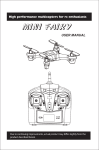
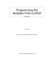
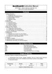
Turul 783 and 784 Telemetric FPV ultra long range remote control kit with 12 channels User Manual The Turul 783 and 784 is a model remote control system which was designed with safe, long range flights in mind. Thanks to its unique technology, it is capable of stable and long range operation with minimal power consumption. A set of unique properties of the device which ensure reliable service: Guaranteed 10 km range Diversity system for perfect signal reception in any position Telemetric connection: two-way communication between the transmitter and the receiver Professional, individually tuned antennas Built in LNA (Low Noise Amplifier) and microstrip technology for long range and reliability 12 standard compliant servo outputs (5V PWM) or CPPM8 output for user friendly connection with Flight Controller (5V) + 1 servo output + 3 switching outputs 4 extra channels so the 8 channel transmitter panel can be extended to 12 channels PPM8/PPM9/PPM12 input, 5V/3.3V/1.8V transmitter panel compatible remote controller Intelligent channel identification 2 analogue input for external sensors 3 stage transmitter power adjustment in case of loss of signal Internal region setting jumper Fail Safe system which is programmable during flight Land navigation software (Turul Remote Console), real time flight data monitoring (also on map), saving and replay of flight data 868MHz ISM/SRD band FHSS frequency fluctuation mode for interference free and stable connection Increased external noise protection with special SAW filters Multiple alerts (Turul Remote Console and transmitter panel) in case of weak or lost signal RSSI output for OSD or Flight Controller/robot Internal high performance, high efficiency power supply The transmitter module can be directly connected to 3S-4S LiPo batteries (power supply voltage: 9-18V) Transmitter module power consumption: 30-240mA The receiver module can be directly connected to 2S-3S LiPo batteries (power supply voltage: 6-16V) Receiver module power consumption: 20-40mA © 2008-2013 www.turulrc.com V2.4 1/8 CONTENTS OF THE KIT Turul 784 – 12 channel receiver module Turul 783 – 12 channel transmitter module Professional custom tuned receiver (2x) and transmitter (1x) antenna USB adapter for the Turul Remote Console program 3 stage transmitter power adjustment switch Fix the transmitter unit (Turul 783) to the back side of the model remote (transmitter panel) or, in order to achieve longer range, fix the unit on an external stand (i.e.: a camera stand). Connect the module to the remote’s PPM output and to the Power supply. The receiver should be placed on the model aeroplane / quadcopter / helicopter. The remote controlling works with two-way communication on an 868 MHz SRD ISM band so the signal quality of the remote can be adjusted at all times. In case the signal weakens, the transmitter module alerts the user with sound. If the Turul 783 is connected to a PC, the Turul Remote Console provides real time monitoring of the following flight parameters: GPS coordinates (only if a GPS receiver is also connected) Momentary speed Flight direction Temperature Battery charge 2 analogue input values (i.e.: voltmeter, RPM counter etc.) Signal strength Quality of connection Quality of GPS signal The program can monitor flight path on a map which can be saved and replayed at any time. The Turul 784 receiver module’s control outputs fit well with model control systems in use. 12 standard servo outputs or 1x CPPM8 (1-8 channels composite signal) or 1x standard servo and 3x TTL switch outputs can be chosen. In addition, the receiver has an analogue RSSI output which can be connected directly to an OSD module or a Flight Controller module. Besides the above mentioned, it is also capable of receiving a GPS module and 2x analogue sensor signals as well, such as a voltmeter. © 2008-2013 www.turulrc.com V2.4 2/8 Turul 784 Receiver LED1 LED2 filtered power supply voltage output and GPS receiver input 2x analogue input Analogue RSSI output for OSD Servo 1 / or PPM8 output Servo 2 output PPM8 mode jumper Servo 12 output LED3 LED4, 5 Power supply voltage jumper (do not alter it) Power supply input (12V) SMA for the antennas Status LEDs: LED1 On: CPPM8 mode enabled Off: 12 channel standard servo mode active LED2 On: The receiver is in a continuous connection with the transmitter Slow blink: No connection with the transmitter Flashing: Pairing in progress, (BIND) mode active LED3 Off: receiving Flashing: transmitting Blinking simultaneously with LED 2: No connection with the transmitter LED4 & LED5: Signals the activity of diversity mode (antenna switching) Teaching the receiver (BIND) The transmitter and receiver modules should be paired before the first use (BIND): 1. Plug the jumper to the An1 and An2 stations. 2. Power up the receiver. 3. Power up the transmitter. 4. If LED2 is on, the pairing was successful. 5. Power down the receiver. 6. Unplug the jumper. Receiver modes and channel allocations The Turul 784 receiver can be used in two modes. The modes can be switched by plugging the jumper on either the Ch2 or the Ch3 servo output. The jumper can only be plugged or unplugged if the receiver is completely powered down! © 2008-2013 www.turulrc.com V2.4 3/8 Standard mode: The Jumper is unplugged from both the Ch2 and Ch3 servo outputs. In this mode 12 standard servos can be connected to the outputs. The below table shows what is indicated on the outgoing channels with different transmitter panels. Receiver Output Ch1 Ch2 Ch3 Ch4 Ch5 Ch6 Ch7 Ch8 Ch9 Ch10 Ch11 Ch12 Output type Servo output Servo output Servo output Servo output Servo output Servo output Servo output Servo output Servo output Servo output Servo output Servo output Transmitter output: PPM8 PPM9 PPM12 PPM-1 PPM-1 PPM-1 PPM-2 PPM-2 PPM-2 PPM-3 PPM-3 PPM-3 PPM-4 PPM-4 PPM-4 PPM-5 PPM-5 PPM-5 PPM-6 PPM-6 PPM-6 PPM-7 PPM-7 PPM-7 PPM-8 PPM-8 PPM-8 Tx-9 PPM-9 PPM-9 Tx-10 Tx-10 PPM-10 Tx-11 Tx-11 PPM-11 Tx-12 Tx-12 PPM-12 Ch(x): receiver channels (“x” marks the value) Servo output: (0-5V TTL/1-2ms/1.5ms neutral) output PPM8, PPM9, PPM12: incoming PPM signal from the transmitter panel PPM-1, PPM-2, PPM-(x): the transmitter panel PPM signal (“x” marks the value) Tx9, Tx10, Tx11, Tx12: transmitter module additional inputs CPPM8 mode: Place a jumper between the receiver’s Ch2 and Ch3 servo outputs. In this mode we can use 1x CPPM8 output, 1x standard servo output and 3x TTL switch outputs. Depending on the incoming PPM signal on the transmitter panel trainer’s port the receiver’s channel allocation is as follows: Receiver Output Ch1 Ch2 és Ch3 Ch4, 5, 6, 7, 8 Ch9 Ch10 Ch11 Ch12 Output type CPPM8 output JUMPER Unused Servo output TTL switch output TTL switch output TTL switch output Transmitter output: PPM8 PPM9 PPM12 PPM1-8 PPM1-8 PPM1-8 empty empty empty empty empty empty Tx-9 PPM-9 PPM-9 Tx-10 Tx-10 PPM-10 Tx-11 Tx-11 PPM-11 Tx-12 Tx-12 PPM-12 Aside from the above: CPPM8: Composite PPM output including the signals of 8 channels Unused: These outputs are inoperable in this mode; do not connect anything to them TTL switch output: output with 0 or 5V charge values The connected outputs can be used for: OSD control, camera exposure control or relay control. When switched off 0V, when switched on 5V will show on the actual channel output. Maximum load per channel: 5mA. In case of higher power requirements switch the transistor as the 2. Figure shows. figure 2. © 2008-2013 www.turulrc.com V2.4 4/8 Placement of receiver antenna The receiver in diversity system is working with two antennas. The Turul 784 always switches to the antenna which has better signal reception. The switching between the antennas is fully automatic. The use of this technology is important with model RC aeroplanes because when in flight, these machines rotate in a three dimensional space so perfect and continuous connection can only be achieved with multiple antennas. For optimal operation, the antennas are placed in a 90 degree deviation in relation to each other as shown in figure 3. or 4. figure 3. L shape: One antenna can be placed vertically downwards while the other can be placed level under the wings (see red antennas) figure 4. V shape: Above the fuselage and wings (see red antennas) In case of quadcopters or multicopters place the antennas level and perpendicular on each other. In this case the transmitter antenna should be placed level as well. figure 5. ATTENTION! There should be no metal or carbon fiber objects or any electrical cables (minimum 5cm) along the entire length and turning radius of the antennas. If achieving this is a problem, place the antennas as far away from the interfering objects as possible. For fixing the antennas in place use non-metal or transparent duct tape (the colored ones are not suitable for this purpose). Only stick the antennas to plastic, wooden or glass fiber materials as these materials do not interfere with operation. Never fix or stick the antennas to metal or carbon surfaces, pipes and do not insert it into other pipes. Never place the antennas beside the battery or to a position which is concealed by the battery. Do not shrink-wrap the antennas. Do not apply paint on the antennas. The transmitter and the receiver antennas should never make physical contact with each other during operation. Minimal distance of the transmitter and receiver antennas during operation is 1-2 meters because in high performance mode insufficient distance can cause malfunction. Placement of receiver After placement of the antennas the length of the cables determines the place of the receiver. It is advised to stick it together with other electronic devices as the other device can cause interference with RF noises which can affect the receiver’s range. Usually OSD modules/robots and intelligent cameras release considerable noise therefore these object’s position should be considered. Requirements to achieve high range In order to achieve high range and safe remote controlling the below requirements should be met. Only use interference free devices near the receiver The Turul 783 transmitter and the Turul 784 receiver antennas should have physical line of sight on each other (i.e.: with an imaginary flashlight, the remote controlled plane can be lit up). If there is no physical line of sight between the two objects, there will be a connection still but range could suffer. It is needed that between the transmitter and the receiver, the so called “Fresnel zone” is completely empty (figure 6.). In case of a 10 km (D) distance the Fresnel ellipse should have a 29.3 meter diameter (r). Accordingly, (if the land is completely level) it is required that between the receiver and the transmitter, there should be a minimum height difference of 2xr=2x29.3=58.6 meters. If the land below is not level, then the highest point should be used for reference to achieve the above mentioned 58.6 meter minimum. figure 6. © 2008-2013 www.turulrc.com V2.4 5/8 Testing, filtering and elimination of possible interferences Keep the antennas far away from OSD modules, robots and cameras because these can release RF noises which can cause interference with the remote control or decrease its range. In order to filter possible interferences, during first assembly after the changing, re-cabling and replacing of devices, always perform a range test on land. The range test is needed so possible interferences by other devices on the machine which can cause range to decrease can be rooted out. Testing should be performed in an area where the transmitter and receiver both has physical line of sight on each other without any concealment (line of sight test). If during line of sight test there are no problems with reception on a 10 km distance, then there are no interferences. (The most suitable place for line of sight test could be a mountain side and plain land under it). In case of interference, the following is advised to find its source(s) Go for a distance where the remote controller does not have continuous reception then going backwards, find the spot where there is still a continuous signal reception. Turn on the devices on the plane orderly, (OSD, robot, camera, video transmitter etc.) If any of the devices cause interference, the remote controller’s signal will suffer after the interfering device is turned on. All sources of interference should be eliminated! Elimination of interference: Put the interfering device further away from the receiver and the antennas Conceal the interfering device whit sheet metal (i.e.: with a 0.5mm thick aluminum sheet) Electronic devices can also be used (i.e.: condensers or coils) but this requires some electrical knowledge and the correct device) If the source of interference cannot be eliminated, the interfering device should be replaced Never fly with an interfering device as this can cause an accident, or damage the controlled device. The remote controller can only achieve the 10 km or higher signal range if the above mentioned installation requirements are met. ATTENTION! Incorrect placement of devices or usage of unsuitable devices can cause serious malfunctions in radio communications which can result in considerable range reduction or complete signal loss in which case the controlled helicopter, quadcopter or aeroplane could crash. For a faulty connection, placement or using of unsuitable devices by the user, neither the manufacturer nor the distributor will be responsible for the resulting damages! Receiver RSSI output wiring The quality of the signal reception of the receiver will show on the RSSI connector. No external devices are needed for its wiring, it can be directly wired onto the OSD or the Flight Controller’s input. The RSSI fluctuates between 0-3.3V according to the quality of signal reception. If the quality decreases, the RSSI value also decreases. If the RSSI value is close to 0, this information is not only visible on the OSD but the remote controller will also send a beeping alert to the user. In this case, increase radio performance and steer the plane back to base. 2 analogue input wiring Use 0-20V DC current on the analogue inputs. The voltage values will show on the land observation program in the Turul Remote Console. Power supply connection The receiver works with a 6-16V current, so it can directly connected to LiPo batteries with 2-3 cells. Servo connection Servos and motor controllers should be connected to Ch2-Ch12 outputs as depicted by figure 7. The black wire (GND) should be on the left side. Depending on the active mode of the receiver the modes of the outputs change as well! (for more information, consult the “Receiver modes” chapter.) The receiver does not supply power to the servos. For use of servos, power can be supplied from motor controllers (BEC) or voltage converters (UBEC). figure 7. GPS connection The receiver supports the connection of a GPS receiver. GPS parameters: 38400 bps, 8n1, 1-10Hz refresh rate, NMEA mode. Most robots and OSDs use GPS receivers with the above settings so it can be connected simultaneously to the Turul 784 receiver module with one cable. © 2008-2013 www.turulrc.com V2.4 6/8 The Turul 783 Transmitter Module Correct wiring of the Turul 783 transmitter module: At the bottom of the transmitter module there is a 16-pin connector block and a status LED. The SMA antenna connector and the signal status LED are on the top of the transmitter module. Correct wiring the transmitter module connector block: Connecting the 4 upper channels 11 = CH9, 13 = CH11, 12 = CH10, 14 = CH12, 8, 10 = GND Correct wiring of the transmitter power 2 1 4 3 6 5 8 7 10 9 12 11 14 13 1, 2 = GND 3 = PPM input from the remote controller Transmitter power sw: 7 = GND 16 15 15= + 12V Connect the switch and the 1K Ohm resistor unit to the transmitter’s 7. and 9. plugs. (GND and Pwr switch plugs) 9 = Pwr switch USB computer interface connection: 5: TTL/RS232 RX - USB dodge TX pin 6: TTL/RS232 TX - USB dodge RX pin 7, 8: GND - USB dodge GND pin 16= GND The switch and the 1K Ohm resistor unit Transmitter power switch The Turul 783 transmitter module’s output power, if needed, is 3-way adjustable. The switch is very helpful in case of lack of continuous remote controlling. In this case increase transmitting power and steer the plane out of radio concealment. From the three stages of transmitting power the first is the lowest and the last one pushes the transmitter into the highest power mode. After adjusting power, a beep will indicate which stage was activated. If the switch is not wired in the transmitter module, it will transmit on the lowest level by default. The transmitter also supports the PPM8, (most of the transmitter panel trainer connectors use this) PPM9 (“Aurora”) and the PPM12 (“Futaba T12”) formats as well. With the TurulRc system, because of the way it works, the transmitter panel with 8 channels can be easily extended to 12 channels. The transmitter identifies the connected transmitter panel’s PPM signal after every time it is powered up and until it is powered down again, it will only accept the same PPM format so during use, it is not possible to switch to other modes (i.e.: from PPM8 to PPM12). Correct wiring of Ch9-Ch12 extra channels These inputs are only operable if a PPM8/PPM9 type output signal transmitter panel is used )for more information consult the “Receiver modes” chapter) To control the Ch9-Ch12 outputs, all the assigned switches, buttons or potentiometers should be wired into the transmitter module. © 2008-2013 www.turulrc.com V2.4 7/8 The fail safe The fail safe is a protective function which activates in case of a remote controller failure (i.e.: the plane is in radio concealment or the battery died in the transmitter). In this mode, the receiver resets every channel to a pre-programmed state so the remote controlled plane does not crash or in case of remote controlling a robot, the robot should become aware of the break of remote signal. The fail safe can be programmed in flight as well. To store the desired fail safe values, press the learn fail safe button with a stick. The successful storage of the values of all the 12 channels will be followed by a beeping sound. After a successful storage of fail safe values, all the channels will reset to the pre-stored values in case of a signal break. ATTENTION! Do not take off without successfully storing fail safe values because it is dangerous! It is advised to turn off the radio-transmitter panel’s radio (2.4 GHZ). PPM signal in case of a “Futaba” radio When using a Futaba radio, use the trainer port connector on its back side. The transmitter panel only switches into transmitting mode if it receives a valid PPM signal through its input. Beeper The built in beeper and its alerts: Alert Description ## Low transmitting power ##--## Medium transmitting power ##--##--## High transmitting power # - - - - - - - repeating Approaching end of range # - # - # - # - repeating Remote control signal break #-#-#-## - - - repeating Fail safe programming Transmitter panel error Cause the power switch is in the 1. Stage the power switch is in the 2. Stage the power switch is in the 3. Stage weakening radio connection can have multiple causes, i.e.: depleted battery, radio concealment etc. learn fail safe button was pushed no incoming PPM signal from the transmitter panel Legend: #: short beep ##: long beep -: break Placement of the transmitter panel The transmitter panel’s antenna should just simply be screwed onto the SMA connector on top of the box. It is advised to place the module higher than the surrounding landmarks and people (+0.5 meter). The transmitter can also be placed on the back side of the remote controller but then range will suffer. If the box is fixed on a stand, no object should reach higher on the stand than the box itself. Transmitter operation norm The device is sold worldwide. In order to ensure the operation of the system complies with international regulations and standards, the device can be operated in two modes. After removing the box of the transmitter you will find a jumper. In “EU” position, the transmitter works according to the regulations of the European Union. In “NonEU” position, it is transmitting on a higher power mode which is allowed in some countries. Before using the device, make sure which power level is allowed in the given country! During extended periods of high power transmitting, the transmitter module will heat up. The temperature of the sheet metal at the back side should not exceed 45°C! If needed, prevent overheating with the use of a heat sink. © 2008-2013 www.turulrc.com V2.4 8/8