1
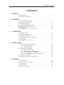
A L W A Y S
A T
T H E
F O R E F R O N T
O F
T E C H N O L O G Y
Instruction Manual
M
A
N
U
A
L
Simrad IS12
Wind Instrument
III
IS12 Wind Speed/Angle
© 2002 Simrad Ltd
The technical data, information and illustrations contained in this publication were to the best of our knowledge correct at the time of
going to print. We reserve the right to change specifications, equipment, installation and maintenance instructions without notice as
part of our policy of continuous development and improvement.
No part of this publication may be reproduced, stored in a retrieval system or transmitted in any form, electronic or otherwise without
prior permission from Simrad Ltd.
No liability can be accepted for any inaccuracies or omissions in the publication, although every care has been taken to make it as complete and accurate as possible.
IV
E04054 Issue 1.1 11/01/02 MDL
Instruction Manual
CONTENTS
1
GENERAL
1.1 Introduction . . . . . . . . . . . . . . . . . . . . . . . . . . . . . . . . . . . . . . . 6
1.2 IS12 Network System . . . . . . . . . . . . . . . . . . . . . . . . . . . . . . . . 7
2
OPERATION
2.1
2.2
2.3
2.4
2.5
2.6
2.7
3
CALIBRATION
3.1
3.2
3.3
3.4
3.5
3.6
4
Apparent Wind Angle . . . . . . . . . . . . . . . . . . . . . . . . . . . . . . . 8
Apparent Wind Speed . . . . . . . . . . . . . . . . . . . . . . . . . . . . . . . 8
High Wind Alarm . . . . . . . . . . . . . . . . . . . . . . . . . . . . . . . . . . . 9
True Wind Angle & Speed . . . . . . . . . . . . . . . . . . . . . . . . . . . . 10
Digital Close Hauled Display . . . . . . . . . . . . . . . . . . . . . . . . . 11
Backlighting . . . . . . . . . . . . . . . . . . . . . . . . . . . . . . . . . . . . . . . 12
Remote Control / Alarm Option . . . . . . . . . . . . . . . . . . . . . . . 13
Selecting Units . . . . . . . . . . . . . . . . . . . . . . . . . . . . . . . . . . . . . 15
Transducer Orientation . . . . . . . . . . . . . . . . . . . . . . . . . . . . . . 16
Wind Angle Offset . . . . . . . . . . . . . . . . . . . . . . . . . . . . . . . . . . 17
Local & Network Backlighting . . . . . . . . . . . . . . . . . . . . . . . . 18
Shop Mode . . . . . . . . . . . . . . . . . . . . . . . . . . . . . . . . . . . . . . . . 19
Disable Remote Control . . . . . . . . . . . . . . . . . . . . . . . . . . . . . . 19
INSTALLATION
4.1 Instrument Head Installation . . . . . . . . . . . . . . . . . . . . . . . . . . 20
4.1.1 Front Mounting . . . . . . . . . . . . . . . . . . . . . . . . . . . . . . 20
4.1.2 Rear Mounting . . . . . . . . . . . . . . . . . . . . . . . . . . . . . . . 22
4.2 Transducer Installation . . . . . . . . . . . . . . . . . . . . . . . . . . . . . . . 23
4.2.1 Running the Cable . . . . . . . . . . . . . . . . . . . . . . . . . . . . 23
4.2.2 Fitting the Masthead Bracket . . . . . . . . . . . . . . . . . . . 23
4.2.3 Assembling the Transducer . . . . . . . . . . . . . . . . . . . . . 24
4.2.4 Attaching/Removing the Transducer . . . . . . . . . . . . 25
4.3 Electrical Installation . . . . . . . . . . . . . . . . . . . . . . . . . . . . . . . . 26
4.4 Electronic Interference Suppression . . . . . . . . . . . . . . . . . . . . 27
5
APPENDIX
5.1
5.2
5.3
5.4
5.5
Fault Finding . . . . . . . . . . . . . . . . . . . . . . . . . . . . . . . . . . . . . . . 28
Spares and Accessories . . . . . . . . . . . . . . . . . . . . . . . . . . . . . . . 28
Dimensions . . . . . . . . . . . . . . . . . . . . . . . . . . . . . . . . . . . . . . . . 29
Specification . . . . . . . . . . . . . . . . . . . . . . . . . . . . . . . . . . . . . . . 29
Service & Warranty . . . . . . . . . . . . . . . . . . . . . . . . . . . . . . . . . . 29
V
IS12 Wind Speed/Angle
1 GENERAL
1.1 Introduction
The Simrad IS12 System is a flexible modular series of instruments that offer large, clear displays, easy to operate functions
and robust, weatherproof construction. Whether as a stand
alone instrument, or as part of a networked navigation system,
the IS12 Wind system will offer superb performance.
LIGHT
WIND
ALARM
TRUE
APP
INFO
Fig 1.1 - IS12 Wind Speed/Angle Instrument
The IS12 Wind system is supplied complete with a masthead
transducer, a power cable and a 30m (98’) transducer cable. All
functions are easily accessed, thanks to IS12’s intuitive, user
friendly control system.
Thank you for choosing Simrad.
If you are pleased with your instrument we hope you will be
interested in our range of marine electronic equipment, which
is manufactured to the same high standards as IS12. Please
contact your nearest Simrad agent for a catalogue showing our
increasing range of high tech navigational instruments, GPS,
Autopilots, Radar, Fishfinders and VHF radio sets.
Simrad operate a policy of continual development and reserve
the right to alter and improve the specification of their products without notice.
6
E04054
Instruction Manual
1.2 IS12 Network System
The IS12 system is built around a high speed bus networking
system that allows instruments to be easily interconnected and
share data.
All units are interconnected and powered using a standard single cable (Fig 1.2) -
COMPASS Tx
WIND Tx
MEGA
DATA
WIND
SPEED/LOG
DEPTH
COMPASS
CONTROLLER
ALARM
Fig 1.2 - IS12 Network System
Additional instruments can be added to the system to act as
repeaters, for example at the chart table of a sailboat or the flybridge of a powerboat. Thus, as shown in the example above,
the Mega and Data Repeater instruments repeat the information from the main instruments. Additional analogue wind
instruments can also be added to the system.
E04054
7
IS12 Wind Speed/Angle
2 OPERATION
2.1 Apparent Wind Angle
When the IS12 Analogue Wind instrument is switched on, the
apparent wind angle is shown as an analogue readout (Fig 2.1) -
LIGHT
WIND
ALARM
TRUE
APP
INFO
Fig 2.1 - Analogue Wind Angle Display
The pointer indicates the direction that the wind is coming
from, relative to the boat (indicated by the “boat shape” on the
fascia). In this example, the wind angle is 45º from the starboard bow. The wind angle can also be displayed digitally see Section 2.5 for further details.
NOTE
As a standalone instrument, the Analogue Wind instrument
can only show the apparent wind angle - this is the direction the
wind appears to be coming from, which is distorted by the forward velocity of the boat. In practical terms, this is the correct
wind angle to trim to, but true wind angle and speed information can also be displayed if there is input from an IS12 Speed
Log or Combi instrument. See Section 2.4 for more details.
2.2 Apparent Wind Speed
Units indicator
The apparent wind speed is shown on the digital display. This
can be shown in knots, metres/sec, miles per hour or Beaufort
(selected in the Units calibration function - see Section 3.1). A
digital marker indicates the units selected (Fig 2.2).
See note above regarding true wind speed information.
Fig 2.2 - Apparent Wind Speed
8
E04054
Instruction Manual
2.3 High Wind Alarm
The Analogue Wind instrument features an alarm that can be
set to sound if the wind speed goes above a specified value.
Press the WIND ALARM key. The display will show ALM
briefly, then change to the current wind alarm setting (Fig 2.3) -
LIGHT
WIND
ALARM
TRUE
APP
INFO
Fig 2.3 - Wind Alarm
Two icons (
and
) appear at the bottom of the display these correspond with the WIND ALARM and TRUE/APP
keys, indicating that pressing WIND ALARM will decrease the
setting and pressing TRUE/APP will increase it. The LIGHT
and INFO keys also have icons printed on the fascia above
them ( and respectively) - pressing (LIGHT) will cancel
or abort an entry and (INFO) will confirm or accept it.
Press the
or
required setting.
NOTE
keys to adjust the wind alarm value to the
Press
to turn the alarm off.
Press
to confirm and return to the main display.
If no key is pressed within 5 seconds, the display will exit to
the default display and any changes will be ignored.
If the alarm sounds, press WIND ALARM to cancel it.
E04054
9
IS12 Wind Speed/Angle
2.4 True Wind Angle & Speed
The Analogue Wind instrument can also show true wind angle
and wind speed information, but boat speed information will
be required in order for this to be calculated, which can be supplied by an IS12 Speed Log or Combi instrument (Fig 2.4) Speed Log/Combi
Analogue Wind
Masthead
Transducer
Speed
Transducer
Fig 2.4 - Minimum IS12 System for True Wind Data
When boat speed data is supplied to the Analogue Wind
instrument, pressing the TRUE/APP key will toggle between
Apparent Wind Angle/Speed and True Wind Angle/Speed
display. The arrow on the LCD display will point to either
APP or TRUE indicating which type of data is currently being
displayed (Fig 2.5) Apparent
Wind Mode
LIGHT
WIND
ALARM
TRUE
APP
INFO
LIGHT
WIND
ALARM
TRUE
APP
INFO
True
Wind Mode
Fig 2.5 - Apparent and True Wind Mode Indicators
10
E04054
Instruction Manual
2.5 Digital Close Hauled Display
The Wind Angle can also be displayed digitally - pressing the
INFO key switches between the wind speed and close hauled
wind angle digital displays (Fig 2.6) -
LIGHT
WIND
ALARM
TRUE
APP
INFO
LIGHT
WIND
ALARM
TRUE
APP
INFO
Fig 2.6 - Switching to Digital Close Hauled Display
When showing the close hauled wind angle, the graphic on the
left of the display indicates the direction of the wind.
When sailing close hauled, the digits show the wind angle
measured from the bow of the boat (Fig 2.7) -
Close hauled, port tack
Close hauled, starboard tack
Fig 2.7 - Wind Direction Indicator - Close Hauled
When running, the digits show the wind angle measured from
the stern, indicating how close the boat is to gybing (Fig 2.8) -
Running, port tack
Running, starboard tack
Fig 2.8 - Wind Direction Indicator - Running
When boat speed data is being received (see Section 2.4),
pressing TRUE/APP will switch the digital display between
apparent and true wind angle.
E04054
11
IS12 Wind Speed/Angle
2.6 Backlighting
The backlighting illuminates the display and the keys, with five
levels of brightness.
To switch the backlighting on, press the LIGHT key. The display will illuminate and the digital display will show the current lighting level (Fig 2.9) -
LIGHT
WIND
ALARM
TRUE
APP
INFO
LIGHT
WIND
ALARM
TRUE
APP
INFO
Fig 2.9 - Turning Backlighting On
Two icons will be shown on the bottom line of the display (
and
), corresponding to the WIND ALARM and TRUE/APP
keys. Press
to increase the brightness (max 5),
to
decrease it (min 1), (INFO) to confirm the selected brightness or (LIGHT) to turn the backlighting off.
The backlighting can either be Local or Network controlled. Local
control means that any adjustments to lighting will only affect
this specific display. With Network control, all instruments in
the network will be affected. See Section 3.4 for more details.
12
E04054
Instruction Manual
2.7 Remote Control / Alarm Option
The optional remote control allows all functions of each instrument to be remotely controlled. Any alarms sounded are also
repeated on this unit. See Section 3.6 regarding enabling and
disabling remote control functionality for this instrument.
As this unit is intended to control all instruments in the IS12
range, the keypad is a generic design. Fig 2.10 indicates the
respective key positions -
LIGHT
WIND
ALARM
TRUE
APP
INFO
Select
Instrument
Fig 2.10 - Remote Control Key Positions
E04054
13
IS12 Wind Speed/Angle
3 CALIBRATION
To protect the calibration functions, these are held in a hidden
menu. To enter calibration mode, press and hold the LIGHT
key. The digital display will show CAL briefly, then change to
UNIT (Fig 3.1) LIGHT
WIND
ALARM
TRUE
APP
INFO
LIGHT
WIND
ALARM
TRUE
APP
INFO
Fig 3.1 - Entering Calibration Mode
Once in calibration mode, pressing the
(WIND ALARM) or
(TRUE/APP) keys will cycle through the available calibration options - Units (Section 3.1)
- Fore/Aft Transducer Mounting (Section 3.2)
- Wind Angle Offset (Section 3.3)
- Local / Network Backlighting (Section 3.4)
- Shop Mode (Section 3.5)
- Disabling Remote Control Facility (Section 3.6)
To exit calibration mode, press and hold
14
(LIGHT).
E04054
Instruction Manual
3.1 Selecting Units
Enter calibration mode and press (INFO). The wind speed
units can then be selected (knots, metres/sec, miles per hour or
Beaufort) by pressing the
or
keys (Fig 3.2) -
LIGHT
WIND
ALARM
or
TRUE
APP
INFO
Fig 3.2 - Selecting Wind Units
NOTE
E04054
Press
(INFO) to set the selected wind units.
Press
point.
(LIGHT) to exit to the main calibration menu at any
15
IS12 Wind Speed/Angle
3.2 Transducer Orientation
For some installations, it may be necessary to mount the masthead transducer facing aft, rather than forward as is usual. If
this is the case, the following procedure should be followed to
avoid the displayed wind angle being 180º out.
Enter calibration mode, press
ADJ) and press (INFO).
once (the display will show
The display will show FORE, indicating that the Analogue
Wind instrument is calibrated for the standard masthead installation. Press
, and the display will change to AFT (Fig 3.3) -
LIGHT
WIND
ALARM
TRUE
APP
INFO
LIGHT
WIND
ALARM
TRUE
APP
INFO
Fig 3.3 - Adjusting Transducer Orientation
Press to confirm - the Analogue Wind instrument is now calibrated for an aft mounted masthead transducer.
The display will then return to the main calibration menu.
NOTE
16
Press
to exit to the main calibration menu at any point.
E04054
Instruction Manual
3.3 Wind Angle Offset
If the masthead transducer has not been fitted so that it is
pointing precisely fore-aft, it will be necessary to adjust the displayed wind angle so that it is correct.
Enter calibration mode, press
twice (the display will show
OFST - Fig 3.4) and press (INFO).
LIGHT
WIND
ALARM
LIGHT
WIND
ALARM
or
TRUE
APP
INFO
TRUE
APP
INFO
Fig 3.4 - Entering Wind Angle Offset
The display will show the current wind angle as read from the
masthead transducer. Use the
and
keys to adjust the
displayed angle to compensate for the mounting error until the
displayed wind angle is correct.
Press to confirm - the Analogue Wind display is now calibrated.
The display will then return to the main calibration menu.
NOTE
E04054
Press
to exit to the main calibration menu at any point.
17
IS12 Wind Speed/Angle
3.4 Local & Network Backlighting
The instrument backlighting can be set so that any changes to
the backlighting are duplicated across all IS12 instruments
installed on the boat (Network), or so that any changes are limited to this specific instrument only (Local).
NOTE
The IS12 instruments are set to Networked lighting as default.
Enter calibration mode, press
three times (the display will
show LIGHT) and press (INFO).
The digital display will show the current setting - NET for
Networked or LOC for Local. The setting can be changed
using the
or
keys (Fig 3.5) -
LIGHT
WIND
ALARM
LIGHT
WIND
ALARM
or
TRUE
APP
INFO
TRUE
APP
INFO
Fig 3.5 - Local and Network Backlighting
To set the selected backlighting, press
return to the main calibration menu.
. The display will then
NOTE
Press
NOTE
Any changes will affect this specific instrument only.
18
to exit to the main calibration menu at any point.
E04054
Instruction Manual
3.5 Shop Mode
This is a simulation mode for in-store demonstration - do not
use.
3.6 Disable Remote Control
On some installations which includes the IS12 Remote Control,
it may be more convenient to limit remote control access to
only some instruments on the network - for example on a sailboat with a set of cockpit instruments and chart table repeaters,
it would not be desirable to be able to remote control the instruments on the chart table (Fig 3.6) Chart Table
Remote control disabled
Cockpit Instruments
Remote control enabled
Fig 3.6 - Sailboat system with Remote control of cockpit
instruments only
To disable remote control functionality on this instrument,
enter calibration mode, press
five times (the display will
show CTRL) and press (INFO).
The display will show the current setting - ON for remote control enabled or OFF for remote control disabled. The setting
can be changed using the
or
keys.
To set the selected mode, press
to the main calibration menu.
. The display will then return
NOTE
Press
to exit to the main calibration menu at any point.
NOTE
Any changes will affect this specific instrument only.
For further information on Remote Control operation, please
refer to the user manual supplied with the Remote Control /
Alarm unit.
E04054
19
IS12 Wind Speed/Angle
4 INSTALLATION
4.1 Instrument Head Installation
All IS12 instrument heads are a standard 110 x 110mm (4.3 x
4.3in) size, and can be mounted either from the front or the rear.
4.1.1 Front Mounting
Fig 4.1 - Front Mounting
35mm (1.4in)
minimum
Front mounting (Fig 4.1) is the standard method of fitting and is
the most straightforward. When mounting the instrument head
it is important to ensure that there is adequate clearance behind
the bulkhead for the rear of the instrument with the cables
inserted - allow at least 35mm (1.4 in) clearance (Fig 4.2).
Additionally, the instrument should not be fitted to a surface
that has a curve greater than 1mm (1⁄25 in) across the mounting
area. If fixing to an uneven surface, care should be taken not
to overtighten the screws. When choosing a location, consideration should be given to the water integrity of the gasket seal if
the surface is not flat. IS12 is designed to be weatherproof, but
the rear of the instrument case with its electrical connections
should be protected from moisture as far as possible.
Tools required for installation -
Fig 4.2 - Clearance Required
Behind Bulkhead
-Drill
- 86mm (3.4in) hole saw
- 2.5mm (0.09in) drill bit
- Countersinking bit
Using the self adhesive template supplied, drill the central
aperture for the instrument case using the hole saw, then the
four fixing holes as indicated on the template. If the instruments are to be fixed to a GRP bulkhead, the fixing holes
should be countersunk after drilling, to stop the screws splitting the gelcoat.
ctd -
20
E04054
Instruction Manual
The instrument is 110mm (4.33 in) square, but a distance of at
least 6mm (0.25 in) should be allowed between adjacent units
for the protective instrument cover supplied.
NOTE
Long term exposure to direct sunlight can damage the liquid
crystal display if left unprotected when not in use - always use
the instrument cover supplied.
The easiest way to fit the keypad and the bezel to the installed
instrument head is to locate the keypad in the keyholes in the
bezel and then offer this up to the instrument head, angling the
bezel back slightly to prevent the keypad falling out. The bezel
should click into place when located correctly (Fig 4.3) -
Fig 4.3 - Fitting Keypad and Bezel
To remove the bezel, simply lift the top edge of the bezel
slightly to disengage the locking clips and pull away from the
instrument head (Fig 4.4) -
Fig 4.4 - Removing Bezel
E04054
21
IS12 Wind Speed/Angle
4.1.2 Rear Mounting
When the instrument is rear mounted, only the display can be
seen - the main body of the instrument, including the keypad is
hidden behind the panel. This is a more elegant method of
installation, but does require precise cutting of the apertures into
the bulkhead or dashboard. Therefore, it is recommended that
installation is done by a professional marine installer.
The instrument can be fixed to the panel using either the self
tapping screws supplied (if the panel is thick enough), or using
2mm studs fixed to the rear of the panel which align with the
four fixing holes (Fig 4.5).
Tools required for installation - Drill
- 5mm (0.2in) drill bit
- Fretsaw
- A fine toothed file.
To assist in cutting a precise aperture for the display, a self
adhesive template is supplied with the unit (Fig 4.6) -
Fig 4.5 - Rear Mounting
Cut on
waste side
of template
Fig 4.6 - Cutting Aperture
Fix the template in the correct position and drill four 5mm
holes on the waste side of the four corners of the aperture.
Starting from one of these holes, carefully cut along the dotted
line around the four edges. To ensure the hole is a good fit, cut
slightly inside the line (on the waste side) and then use the file
to smooth the edges until the display fits precisely.
NOTE
22
Because the keypad is not accessible with this method of mounting, the Remote Control unit (see Section 2.7) will be required
to enable control of instrument functions.
E04054
Instruction Manual
4.2 Transducer Installation
4.2.1 Running the Cable
It is easiest to run the transducer cable if the mast is stepped. If
this is not possible, all necessary precautions should be taken always use a bosuns chair and ensure all tools are securely
attached when working aloft.
Apply the self-adhesive template supplied to the masthead,
pointing fore-aft. Drill the fixing and cable exit holes as
marked - the masthead bracket incorporates a cable clamp to
secure the transducer cable and provide strain relief (Fig 4.7) -
Allow 75mm (3.0”) of
cable at the masthead
Cable clamp
channels
Gasket
Cable exit point
MASTHEAD
Fig 4.7 - Drilling Exit Hole for Transducer Cable
The cable can be fed through the side of the mast if this is more
convenient.
NOTE
It is recommended that a grommet is used to avoid damage the
cable where it passes through the mast. Allow at least 75mm
(3.0”) of cable at the masthead for the transducer connection.
For boats with an aluminium mast, a channel is normally provided inside the mast Section for running electrical cables.
This will usually have a tag line, or “mouse” - a length of line
running the length of the mast to assist in pulling through
cables. If not, the cable will need to be fed down and drawn
out the bottom by hand.
Mast Top Cable Exit
Mast Side Cable Exit
Cut out
blanking
piece
For boats with a wooden mast, the cable can be run down the
outside of the mast, held in place with galvanised cable clips.
4.2.2 Fitting the Masthead Bracket
Fig 4.8 - Cable Channel
Exit Points
E04054
Route the transducer cable in the strain relief channels in the
bracket and out the back. If the cable exits through the side of
the mast, route the cable in one of the blanked off side channels and out the back (Fig 4.8). Use a sharp knife or scalpel to
remove the blanking piece and open up the channel.
23
IS12 Wind Speed/Angle
35mm (1.38”)
BOW
Attach the masthead bracket with the screws provided. Ensure
the bracket is mounted the right way round, so that the wand
will be pointing in the correct direction (Fig 4.9). The transducer can be mounted facing aft if required, but it will be necessary to set the transducer orientation to AFT in the calibration
menu (see Section 3.2 for more details).
4.2.3 Assembling the Transducer
20mm (0.78”)
The vane and cups assemblies are packed separately - fit the
vane to the transducer so that the shaft on the top of the transducer fits correctly into the vane (the shaft is keyed so that it
will be aligned correctly). Screw the counterweight in just far
enough to lock the vane into place (Fig 4.10) 1) Fit the vane
Fig 4.9 - Fitting Masthead
Bracket
2) Screw in counterweight
(do not overtighten)
Ensure the shaft
is oriented correctly
Fig 4.10 - Attaching Wind Vane
NOTE
Check that the vane rotates freely - do not overtighten the
counterweight or it may restrict the vane’s movement.
The anemometer cups fit to the base of the transducer body in
a similar way (Fig 4.11). Once fitted, they are held in place by
a grub screw, which should be tightened (using the allen key
supplied) enough to hold the cups in place without restricting
their movement.
1) Fit the cups
2) Tighten Grubscrew
Fig 4.11 - Attaching Anemometer Cups
NOTE
24
Check that the cups rotate freely.
E04054
Instruction Manual
4.2.4 Attaching / Removing the Transducer
The masthead transducer is attached to the masthead bracket
using a simple quick-release clamp system.
1 - Slide the locating pegs on the rear of the transducer base
into the slots on the masthead bracket.
2 - Rotate the transducer down onto the masthead bracket.
3 - The transducer base will then lock into place (Fig 4.12) -
1
2
3
Locating
Peg
Lock
Fig 4.12 - Attaching Masthead Transducer
WARNING
Ensure the quick release clip is properly engaged by pulling it
fully forward.
Fit the transducer cable to the socket in the back of the masthead transducer.
NOTE
To avoid damage, it is recommended that the masthead transducer be taken down at the end of the season if the boat is to
be laid up or lifted out.
Simply remove the transducer cable, pull the release clip back
and lift the transducer off the masthead bracket (Fig 4.13) -
1
2
Lift
Pull back
Fig 4.13 - Removing Masthead Transducer
WARNING
E04054
To avoid corrosion of the electrical contacts, always fit the cover
supplied over the end of the masthead cable.
25
IS12 Wind Speed/Angle
4.3 Electrical Installation
IS12 instruments are ‘daisy chained’ together, with each instrument linking to the previous one by a single cable carrying
power and data (Fig 4.14). The cable plugs into either of the
two circular network ports on the rear of the instrument.
Fig 4.14 - IS12 “Daisychain” Cable System
The cable connectors are keyed so that they will always be correctly oriented when inserting the cable into the instrument the flattened edge of the connector should be facing down
when inserting (Fig 4.15) -
Network Bus Ports
Flattened edge
Fig 4.15 - Rear Connections
The first link in the IS12 system is the power cable, which
should be connected to the boat’s 12v DC supply via a 3 Amp
breaker or fuse as follows Red wire Black wire NOTE
26
12v DC
0v
Only one power cable is required in an IS12 system, but
power must be supplied via an IS12 power cable (with a red
connector end), or the system will not function.
E04054
Instruction Manual
A three way joiner (part no. SDJ) is available as a separate
accessory (Fig 4.16) -
Three Way Joiner SDJ
Fig 4.16 - Three way joiner
The transducer is connected to the instrument using the spare
network port on the rear of the instrument (Fig 4.17) -
Fig 4.17 - Transducer Connections
NOTE
If the boat is fitted with more than one IS12 instrument, it
should be noted that it is not necessary to plug the wind transducer cable directly into the back of the wind instrument - any
spare network port can be used.
NOTE
If the Wind system is being added to an existing IS12 installation with a network terminator fitted, this should be removed
as the masthead transducer already has an inbuilt terminator.
4.4 Electronic Interference Suppression
IS12 has been designed to minimise the effects of interference
generated by the engine alternator. However, precautions
should still be taken by routing the cables away from the
engine compartment. Do not run the cables down trunking
carrying high current cables. The transducer cable should also
be kept separate from the boat’s radio antenna cable if possible.
Engines with spark ignition, also some refrigerators should be
fitted with suppressors. Your local agent should be able to
advise on this and supply suppression kits where necessary.
E04054
27
IS12 Wind Speed/Angle
5 APPENDIX
5.1 Fault Finding
Symptom
Possible Cause
Remedy
No display on any heads • Faulty connection to power
in the system
• Fuse has blown
• Check power connection
• Replace fuse and check
power supply current
No display on one or
more heads in system
• IS12 data cable loose or broken
• Check cable linked to
first faulty unit. Replace if
necessary
Occasional poor
performance
• Electrical interference from other
• Fit interference suppressors
equipment on boat (see Section 4.4) to equipment responsible
Display shows “---”
• Faulty connection to transducer
• Check transducer connection
These simple checks should be carried out before seeking technical assistance and may save time and expense. Before contacting your servicing agent please note the unit’s serial number.
5.2 Spares & Accessories
The following spares and accessories are available from local
Simrad agents. Please quote part number when ordering IS12Wind:R
Analogue Wind Repeater
IS12Mega:R
Digital Repeater
IS12Remote:F Remote Controller
28
SPC2M
Power Cable 2m
SDC0.3M
IS12 Cable 0.3m
SDC02M
IS12 Cable 2m
SDC05M
IS12 Cable 5m
SDC10M
IS12 Cable 10m
SDC30M
IS12 Mast Cable 30m
SDJ
Three Way Cable Joiner
IS12TW
Spare Transducer
ISPK08
Spare Wind Vane Pack
ISPK09
Spare Anemometer Cups Pack
PIC
Spare Sun Cover
ISPK03
Spare Bezel & Keypad Pack - Wind
E04054
Instruction Manual
43mm (1.7in)
180mm (7.0in)
110mm (4.3in)
5.3 Dimensions
80mm (3.2in)
20mm
(0.78in)
17mm
(0.67in)
440mm (17.3in)
110mm (4.3in)
5.4 Specification
Supply Voltage
12v (9-16v) DC
Current Consumption
Light Off - 40mA
Wind Speed Range
0-99.9 Kts, m/s, Km/h (0-12 BFT)
Max Resolution
1º
Max units per system
32
Ambient Temp Range
-10ºC to +55ºC (14ºF to 140ºF)
Light On - 60mA
5.5 Service & Warranty
Your equipment should seldom need servicing, although it will
benefit from an application of silicone or Teflon grease to the
contacts each season. The transducer should be removed at the
send of the season and stored.
The unit is guaranteed for 2 years from date of retail sale. If it is
necessary to have the unit repaired, return it carriage prepaid to
the agent in the country of purchase with a copy of the receipted
invoice showing the date of purchase. Where possible, return
all the components unless you are certain that you have located
the source of the fault. If the original box is not available, ensure
that it is well cushioned in packing; the rigours of freight handling can be very different from the loads encountered in the
marine environment for which the unit is designed.
For Worldwide Warranty details, please refer to the Warranty
Card supplied with this unit.
E04054
29
www.simrad.com
A L W A Y S
A T
T H E
F O R E F R O N T
O F
T E C H N O L O G Y