1
Installation Manual
PPT8/12/16/22LX/LY SLIMLINE
®
OWNER/INSTALLATION MANUAL
FOR
PPT8/12/16/22LX/LY SLIMLINE
(SD638153 Iss.10 08/11/12)
Health and Safety Warning:
As the heat pump includes electrical and rotational components it is required that only trained
and competent persons should remove panels giving internal access to the unit.
SD638153 ISSUE 10
Calorex Heat Pumps Ltd. · The Causeway, Maldon, Essex CM9 4XD, UK
Installation Manual
PPT8/12/16/22LX/LY SLIMLINE
®
Thank you for choosing Calorex!
Your Calorex heat pump has been specially designed for pool heating using high
quality components that are carefully chosen to provide maximum efficiency and
reliability. Please read this manual carefully as it provides useful operation and
maintenance information that will maximise the benefits your Calorex heat pump
can offer.
+
ACCESSORIES
4 x ANTIVIBRATION PADS
2 x 50mm FEMALE PIPE ADAPTORS
1 x CONDENSATE DRAIN SOCKET 3/4”
1 X CONDENSATE DRAIN SOCKET 20mm
(IN HEAT PUMP ELECTRIC BOX)
Page 2
Calorex Heat Pumps Ltd. · The Causeway, Maldon, Essex CM9 4XD, UK
SD638153 ISSUE 10
Installation Manual
PPT8/12/16/22LX/LY SLIMLINE
R
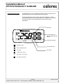
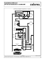
QUICK START GUIDE
7
i
pH CaCO3
8
i
10
i
11
12
1
10
2
3
9
4
8
7
15
6
5
i
H.R.C./ MCB (Type C)
29
1Ø
i
13/23
i
PPT8 = 20A
PPT12 = 25A
PPT16 = 30A
PPT22 = 42A
3Ø
PPT8 = 10A
PPT12 = 10A
PPT16 = 15A
PPT22 = 20A
Page i
Calorex Heat Pumps Ltd. · The Causeway, Maldon, Essex CM9 4XD, UK
Installation Manual
PPT8/12/16/22LX/LY SLIMLINE
®
Contents
QUICK START GUIDE ......................................................................................................i
1.0 Introduction ................................................................................................................ 4
1.1 Function .................................................................................................................... 5
2.0 Installation ................................................................................................................. 6
2.1 Accessories .............................................................................................................. 6
2.2 Siting ........................................................................................................................ 6
2.3 Air flow ...................................................................................................................... 7
3.0 Plumbing ................................................................................................................
8
3.1 Recommended Plumbing Schematic ....................................................................... 10
3.2 Determining Water Flow .......................................................................................... 11
4.0 Electrolytic Corrosion in Swimming Pools ................................................................ 12
4.1 Electrical (Machine Wiring and Supply) .................................................................... 13
4.2 Location of Mains Input and External Interlock Terminals ........................................... 14
4.3 Pool Pump Synchronisation ................................................................................... 15
5.0 Digital Thermostat ................................................................................................... 16
6.0 Circuit Diagrams ..................................................................................................... 17
7.0 Regular planned maintenance ................................................................................. 21
8.0 Heat Pump Malfunction ........................................................................................... 22
8.1 User Check List ....................................................................................................... 22
9.0 Datasheets.............................................................................................................. 23
10.0 Installation Drawings .............................................................................................. 25
11.0 Winterisation Procedure ........................................................................................ 29
11.1 Start up Procedure After Winterisation .................................................................. 30
12.0 Warranty Conditions .............................................................................................. 31
13.0. Contacting Calorex............................................................................................... 32
14.0 Machine Record Log ............................................................................................ 33
Page 3
Calorex Heat Pumps Ltd. · The Causeway, Maldon, Essex CM9 4XD, UK
SD638153 ISSUE 10
Installation Manual
PPT8/12/16/22LX/LY SLIMLINE
1.0 Introduction
®
The Calorex ‘Propac’ range of air to water heat pumps is designed for
swimming pool heating and consists of 4 models. Heat pumps in this
manual are designed to heat pool water and spas within the range of 10°C
to 40°C. Standard units (designated X) are suitable for outdoor pools
operating in ambient temperatures above 5ºC.(Reverse cycle defrost
models (designated Y) operate in ambient temperatures down to
-15ºC).The water heat exchanger is a full flow type, manufactured from
titanium tube, which is a highly corrosion resistant material. The heat
pumps are suitable for use in fresh water and salt water pools. PPT8/12
heat pumps are fitted with rotary compressors and PPT16/22 heat pumps
are fitted with scroll compressors. Both types of compressor are known
for quiet running. A 6 minute compressor start delay timer is incorporated
for compressor protection. With these features the heat pump is designed
to have a long, trouble free life.
All units have integral safety devices to protect the heat pump from internal
and external faults. Indicator lamps indicate operating mode. An adjustable
digital thermostat controls water temperature.
Calorex Heat Pumps Limited is an ISO9001:2000 certified company.
All Calorex heat pumps are CE approved
Page 4
Calorex Heat Pumps Ltd. · The Causeway, Maldon, Essex CM9 4XD, UK
SD638153 ISSUE 10
Installation Manual
PPT8/12/16/22LX/LY SLIMLINE
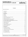
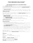
1.1 Function
®
The Calorex Swimming pool heat pump provides thermodynamic heating by
means of a vapour compression cycle, (similar to that employed in a
conventional refrigerator), in addition to acting as an active solar collector.
1. THE EVAPORATOR collects the heat from the outside
ambient air, pre-heated by the sun. In the Calorex swimming
pool heat pumps, high volumes of outside air are drawn into the
unit by the fan expelled through the evaporator fins. The
evaporator has liquid refrigerant passing through it which is at a
THE
PUMP
considerably lower temperature than
theHEAT
ambient
air. CYCLE
Therefore the air gives up its heat to the refrigerant which then
vaporises.This preheated vapour now travels to -
2. THE COMPRESSOR
where it is compressed and
upgraded to a much higher
temperature. The hot vapour
now enters-
THE HEAT PUMP CYCLE
2
COOL GAS
COMPRESSOR
HOT GAS
POOL
WATER OUT
AMBIENT
AIR
3
1
HEAT
EXCHANGER
EVAPORATOR
POOL
WATER IN
COOL LIQUID
REFRIGERANT
LOW PRESSURE SIDE
4. THE EXPANSION DEVICE and from
there, now at normal pressure, it is
returned to the evaporator and the cycle
starts again.
CONDENSED
REFRIGERANT
EXPANSION
VALVE
4
HIGH PRESSURE SIDE
3. THE CONDENSER where it is surrounded
by the pool water. The heat is given up to the
cooler pool water and the now cooler refrigerant
returns to its former liquid state but still under
high pressure from the compressor. This
pressure is released by passing liquid through-
Coefficient of Performance
The efficiency of a Heat Pump is usually called its ‘Coefficient of Performance’ - (C.O.P.)
which is simply a ratio of heat output to energy input, both being expressed in kW. Thus a
Heat Pump absorbing 1 kW of electricity, collecting 4 kW of energy from the air, and
delivering 5 kW of heat to the pool water is said to have a C.O.P. of 5:1.
This ratio will vary according to the temperature of the water and the ambient air.
Page 5
Calorex Heat Pumps Ltd. · The Causeway, Maldon, Essex CM9 4XD, UK
SD638153 ISSUE 10
Installation Manual
PPT8/12/16/22LX/LY SLIMLINE
2.0 Installation
®
a) Ensure heat pump on site is as ordered, i.e. model, electrical supply and factory
fitted options.
b) Inspect unit for damage, in particular inspect the evaporator (finned side) to
ensure that it is undamaged. (Minor indentations in the fins do not affect
performance). If severely damaged, endorse delivery note in presence of the
driver and send a recorded delivery letter to transport company giving details.
Protect unit if installation is delayed.
2.1 Accessories
The heat pump is supplied with accessories which aid installation. On delivery the
accessories are in a plastic bag in the heat pump electric box. (See section 4.2
for lid removal).
These accessories are as follows:
4 x rubber feet - Fit these under the metal feet of the heat pump to help reduce the
effects of vibration.
2 x 50mm female connectors - On delivery the heat pump has 1 1/2” sockets
attached to the water connections for fitting 1 1/2” plastic pipes. If 50mm
pipework is preferred undo the threaded couplings on the water in/out connection
points and carefully remove the 1 1/2” sockets. Then fit the 50mm sockets in
their place and refit the threaded couplings. The heat pump can then be fitted
with 50mm plastic pipe.
2 x Condensate drain piece - Condensate drain pieces are supplied suitable for 3/4”
or 20mm pipe. Use whichever piece fits the drain pipe required. Glue the relevant
piece to the driptray outlet and then fit then condensate drain piping.
2.2 Siting
a) Provide a firm level base capable of supporting operational weight of unit; spread
load if mounted on timber floor.
b) Ensure water cannot collect under unit, it is recommend that units are installed
on plinths 100mm above finished floor level. This also aids condensate drainage.
c) Allow adequate clearance to service panels on unit; recommend 500mm
minimum.
d) All Calorex heat pumps are by design as quiet as is practical, however due
consideration should be given to siting the heat pump in order to minimise the
noise coming from the machine, for example by positioning the machine so that
the inlet/outlets are parallel to occupied premises.
e) Ensure loose debris such as leaves, grass cuttings, etc will not block air inlet
grilles.
f) Consider protection from extreme weather conditions if installed externally, i.e.
lean-to-cover or building.
Page 6
Calorex Heat Pumps Ltd. · The Causeway, Maldon, Essex CM9 4XD, UK
SD638153 ISSUE 10
Installation Manual
PPT8/12/16/22LX/LY SLIMLINE
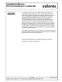
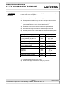
2.3 Air flow
®
Due consideration must be given to air flow i.e. do not obstruct inlet or outlet
and ensure discharge to air cannot recirculate to inlet. (See below).
POSSIBLE POSITIONS OF A CALOREX HEAT PUMP
Suitable opening
Suitable opening
CALOREX
CALOREX
> 50 cm
CALOREX
PLANT ROOM
WALL
CALOREX
WALL
CALOREX
SWIMMING POOL/SPA
MODEL
PPT8
PPT12
PPT16
PPT22
TABLE 1
Minimum Free Area m²
Inlet
Discharge
0.157
0.168
0.264
0.168
0.322
0.173
0.322
0.173
Required Free Areas to provide air flow to and
from heat pumps when installed in an
enclosed area or where required to pass air
through a wall etc.
Free areas is the available area through which
air can pass through a grille or louvres.
IMPORTANT
If multiple units are installed in an enclosed area then the inlet free areas
required for each unit can be added together to form one inlet aperture.
BUT discharge from each unit must be kept separate and must not be
incorporated into one common duct system.
Page 7
Calorex Heat Pumps Ltd. · The Causeway, Maldon, Essex CM9 4XD, UK
SD638153 ISSUE 10
Installation Manual
PPT8/12/16/22LX/LY SLIMLINE
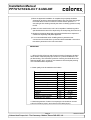
3.0 Plumbing
®
a) Calorex Heat Pumps have water inlet/outlet connections as follows:
All models have fittings which enable the heat pump to be connected to
either 1 ½” or 50mm pipe work.
b) The heat pump is supplied with bungs fitted in the water connection
fittings These need to be removed before the heat pump is installed.
(See section 3.2).
c) The Calorex Heat Pump must be connected after the filter in the return
pipe to the pool. If an existing heater is being retained, then the Calorex
Heat Pump should be connected between the filter and the other heater.
(See section 3.1).
d) Suitable breakable couplings should be installed local to the heat pump.
e) If the heat pump is installed at a lower level than the pool then isolation
valves should be fitted.
f) A drain valve or plug should be fitted to the lower pipe to facilitate drain
down in the winter period.
g) Connections on all models are by 1 ½” or 50mm Female fittings. The
water in/water out pipes need to be glued into these connections using a
suitabe adhesive.
h) The condensate drain at the base of the unit collects condensation from
the evaporator fins. This should run away to waste via ¾” domestic
waste piping. It is therefore necessary to ensure that the Calorex Heat
Pump is placed on a level plinth so that the condensate water can run
away with adequate fall to waste i.e. ½” per foot minimum and must
incorporate a “u” trap as to not overflow the edges of the drip tray inside
the heat pump. See below.
INCORRECT DRAINAGE
FOR CONDENSATE
THIS TYPE OF
INSTALLATION
SHOULD BE AVOIDED
CORRECT DRAINAGE
FOR CONDENSATE
ELBOW
ADEQUATE FALL
'U' TRAP
Page 8
Calorex Heat Pumps Ltd. · The Causeway, Maldon, Essex CM9 4XD, UK
SD638153 ISSUE 10
Installation Manual
PPT8/12/16/22LX/LY SLIMLINE
®
i) When the pipework installation is complete the pool pump should be
switched on and the system tested for leaks. Also check the filter gauge
to see that there is not an excessive increase in back pressure. If
everything is then working normally the water circulating system is ready
for use.
j) Water circuit to and from the unit is to be capable of maintaining within
specified limits the rate of flow required by the heat pump. (See section 9).
k) All pipework must be adequately supported with allowance expansion/
contraction especially with plastic pipework.
l) It is recommended that when installing water systems the last
connections to be made in the system should be breakable connections
to avoid any stresses on the unit connections.
IMPORTANT
1. All Pool Purifying Devices and Chemical Injection Systems to be fitted
down stream of the heat pump (see section 3.1) unless installation is as
per filter dosing. This includes the practice of dosing chemicals direct into
skimmer basket, which results in concentrated corrosive liquids passing
over vulnerable metal components.
2. Water quality must be maintained as follows:
Acidity pH
Total Alkalinity, as CaCO3
pH
ppm
7.2 - 7.8
80 - 120
Total Hardness, as CaCO3
ppm
150 - 250
Total Dissolved Solids
Maximum Salt Content
ppm
ppm
1000 Max
35000 Max
Free Chlorine Range
Free Chlorine Range
Superchlorination
Bromine
Baquacil
ppm
ppm
max
ppm
ppm
1 - 2 Domestic
3 - 6 Commercial
30ppm for 24 hrs
2-5
25 - 50
Ozone
Maximum Copper Content
Aquamatic Ionic Purifier
ppm
ppm
ppm
0.9 Max
1
2 Max
3. Maximum pressure of water in heat pump circuit should not exceed
2.5bar for PPT8/12 (35 psi) and 3.5bar for PPT16/22 (50 psi).
Page 9
Calorex Heat Pumps Ltd. · The Causeway, Maldon, Essex CM9 4XD, UK
SD638153 ISSUE 10
100mm
Page 10
Calorex Heat Pumps Ltd. · The Causeway, Maldon, Essex CM9 4XD, UK
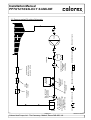
KEY
BYPASS VALVE
(NORMALLY
CLOSED)
CALOREX
HEAT PUMP
NON
RETURN
VALVE
NON RETURN VALVE
FILTER
TO WASTE
SPARE PORT FOR
WINTERISING
FLUSHING
CONNECTION
DEVICE, IF FITTED
SANITISER OR
CHEMICAL DOSING
BREAKABLE COUPLING
CONDENSATE WATER
TO WASTE
ISOLATION VALVE
ANTI RETURN LOOP
TO BE INCORPORATED,
MINIMUM HEIGHT
100mm ABOVE HEAT PUMP
OUTLET PORT
(IF SANITISER FITTED)
TO WASTE FOR
WINTERISING
DRAIN DOWN
AUX HEATER
IF FITTED
THREE WAY VALVE
PUMP
POOL
Installation Manual
PPT8/12/16/22LX/LY SLIMLINE
®
3.1 Recommended Plumbing Schematic
SD638153 ISSUE 10
Installation Manual
PPT8/12/16/22LX/LY SLIMLINE
3.2 Determining
Water Flow
®
The heat pump is fitted with a water flow switch which inhibits the operation
of the heat pump when the water flow is less than the figure shown in the
table below.
MODEL
PPT8
PPT12
PPT16
PPT22
Flow rates for water pressure switch
Machine starts working Machine stops working
when flow rate rises
if flow rate drops below
above L/hour
L/hour
1500
840
1500
840
2500
2000
1920
1500
Adjust the flow rate until the flow rate is adequate. The display on the
digital thermostat shows “noF” until adequate flow is reached.
DIGITAL
THERMOSTAT
POOL WATER
OUT
POOL WATER
IN
REMOVE BUNGS
BEFORE INSTALLING
HEAT PUMP
CONDENSATE DRAIN
PPT8/12 FLOW RATE 4500 L/hour
PPT16 FLOW RATE 7500 L/hour
PPT22 FLOW RATE 9960 L/hour
Page 11
Calorex Heat Pumps Ltd. · The Causeway, Maldon, Essex CM9 4XD, UK
SD638153 ISSUE 10
Installation Manual
PPT8/12/16/22LX/LY SLIMLINE
®
4.0 Electrolytic Corrosion Electrolytic corrosion will occur when dissimilar metals that are in contact
with each other create a potential difference between themselves. Sometimes
in Swimming Pools
separated by a conductive substance known as an electrolyte, the dissimilar
metals will create a small voltage (potential difference) that allows the ions of
one material to pass to the other.
Just like a battery, ions will pass from the most positive material to the more
negative material.
Anything more than 0.3 volts can cause the most positive material to degrade.
A swimming pool with its associated equipment can create this effect. The
pool water being an ideal electrolyte and components of the filtration circuit,
heating system, steps, lights etc providing the dissimilar metals needed to
complete the circuit.
Whilst these small voltages are rarely a safety threat, they can create
premature failure through corrosion. Not dissimilar to corrosion through
oxidation, electrolytic corrosion can cause complete failure of a metallic
material in a very short period of time.
In order to prevent this type of corrosion all metallic components in contact
with swimming pool water should be bonded together using 10mm² bonding
cable. This includes non-electrical items such as metal filters, pump strainer
boxes, heat exchangers, steps and handrails. It is highly recommended that
bonding be retrofitted to existing pools, which may not be protected by this
system.
Page 12
Calorex Heat Pumps Ltd. · The Causeway, Maldon, Essex CM9 4XD, UK
SD638153 ISSUE 10
Installation Manual
PPT8/12/16/22LX/LY SLIMLINE
4.1 Electrical (Machine
Wiring and Supply)
®
All electrical work to be carried out in accordance with l.E.E. standards, latest
issue, or local codes of practice as applicable.
The machine should be installed in line with EMC2004/108/EC.
Protected supply to incorporate fuses or motor type circuit breakers (Type C)
to specified rating, (see Data Sheet). H.R.C. fuses are recommended. An
isolator which disconnects all poles must be fitted within 2m and in sight of
machine.†
All units must be correctly earthed-grounded. An earth leakage trip of the
Current operating type (30mA) is recommended to be fitted to all pool
electrics.
INCONSISTENT ELECTRICAL SUPPLY
The following limits of operation must not be exceeded if Calorex machines are
to be guaranteed either in performance or warranty terms:
Voltage single phase
Voltage three phase
Frequency - Hz
Minimum
Maximum
207V
360V
47,5
253V
440V
52,5
This voltage must be made available at the heat pump while running.
† Note the Isolator must have a minimum of 3mm air gap when turned off.
NOTE: Three phase heat pumps are fitted with a phase protection relay
and will not run if the phases are not connected in the correct order
(phase sequence) or if the supply voltage is 15% less than the nominal
voltage (415V for 3N~ 50Hz). The lamp on the phase rotation relay
(situated in the electric box is illuminated when the phases are correctly
connected and the voltage is sufficient.
IMPORTANT
The user should be made aware that THE WHOLE installation should be
isolated when working on ANY PART.
Page 13
Calorex Heat Pumps Ltd. · The Causeway, Maldon, Essex CM9 4XD, UK
SD638153 ISSUE 10
Installation Manual
PPT8/12/16/22LX/LY SLIMLINE
4.2 Location of Mains
Input and External
Interlock Terminals
®
ENSURE EARTH LEAD IS STILL
CONNECTED
LOOSEN CAPTIVE SCREWS (6)
AND LIFT COVER OFF
ELECTRIC
BOX
MAINS IN
CABLE ENTRY
POINT
SINGLE PHASE 230V ~1N 50Hz
19
18
17
16
15
14
13
12
11
10
9
8
7
6
5
VALVE
SWITCH
FAN
L
FAN
N
REMOTE
INTERLOCKS
ON/OFF
REVERSING
5 6 7 8 9 10 11121314 1516171819
VOLT FREE POOL PUMP
RUN TERMINALS
L
N
ELEC. BOX
EARTH STUD
L
N
MAKE MAINS IN
EARTH
CONNECTION HERE
CABLE ENTRY
POINT
5 6 7 8 9 101112131415 16171819
VOLT FREE POOL PUMP
RUN TERMINALS
L3
L2 L1
REMOTE INTERLOCKS
ON/OFF
N
ONLY
'Y' VRSN
5 6 7 8 9 10111213141516171819
1411
L1 L2 L3
THREE PHASE 400V ~3N 50Hz
ELEC. BOX
EARTH STUD
L3
L2 L1
MAKE MAINS IN
EARTH
CONNECTION HERE
N
Page 14
Calorex Heat Pumps Ltd. · The Causeway, Maldon, Essex CM9 4XD, UK
SD638153 ISSUE 10
Installation Manual
PPT8/12/16/22LX/LY SLIMLINE
4.3 Pool Pump
Synchronisation
®
For installations where the filter pump, which also provides water to your
heat pump, is controlled by a time clock (supplied by the installer) your
Calorex heat pump can overridde “pump off” periods set on the time clock
so that the filter pump will run if your swimming pool requires heating. By
doing so your filter pump will only run when:
a) A block period of pump “running” has been set on the time clock for
filtration purposes.
b) The pool requires heating.
This feature operates by overriding the filter pump time clock for three
minutes each hour so that water is pumped through the heat pump.
If during this sampling period the heat pump detects a need for water
heating it will continue to override the time clock until the swimming pool
temperature is satisfied. If water heating is not required the filter pump will
turn off after the three minute sampling period and not restart untl the next
hourly sampling period or time clock pre set run time. This feature will
reduce filter pump run time and consequently save energy as well as
unnecessary filter pump wear and tear.
L
MAX RATING 3A
½ HP AT 250V
18
19
CUSTOMERS EXTERNAL
PUMP/FILTER TIME CLOCK
CALOREX HEAT PUMP.
EXTERNAL COMPONENTS TO
BE WIRED TO TERMINAL
BLOCK LOCATED INSIDE
MACHINE ELECTRIC BOX.
POOL PUMP
STARTER
N
A pair of volt free terminals (numbered 14 and 15) are available to allow for
the heatpump to be switched on or off remotely.
Page 15
Calorex Heat Pumps Ltd. · The Causeway, Maldon, Essex CM9 4XD, UK
SD638153 ISSUE 10
OVER THE LAZY DOG
123456789!"£$
Installation Manual
%^&*(PPT8/12/16/22LX/LY
) _ +@~
SLIMLINE
{ :<>?,./#';\|<,>.?/
5.0 Digital Thermostat
®
An adjustable touch screen digital thermostat controls and maintains the
water temperature and incorporates the indicator lamps.
Press and release the P key to display required temperature. To alter
required temperature press the up or down keys, a gentle touch is all that
is necessary. After 5 seconds the display reverts to actual water
temperature.
Not used
T CNOLOGiC
U
AUX
P
Increase Set Point
Also start/stop manual
defrost
Decrease Set Point
X31SX
DEFROST LAMP
Access Set Point
WATER HEATING LAMP
Set Lamp
FAN LAMP
ALARM LAMP - FAULT
AUX
AUX LAMP - POOL PUMP
NOT USED (CHILLING)
Page 16
Calorex Heat Pumps Ltd. · The Causeway, Maldon, Essex CM9 4XD, UK
SD638153 ISSUE 10
Installation Manual
PPT8/12/16/22LX/LY SLIMLINE
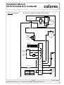
6.0 Circuit Diagrams
®
PPT8/12 ALX SINGLE PHASE 230V~1N 50Hz
SOFT
START
IF
FITTED
RUN CAP
CONTACTOR
5
1
(N/O)
6
(N/O)
R
S COMPRESSOR
2
C
RELAY/HARD
START CAP
IF FITTED
A1
A2
FAN
SOFT START
THERMAL
OVERLOAD
& FAULT
LIGHT
IF FITTED
13
12
POOL STAT
SENSOR
(DEFROST)
10
12
11
SENSOR
(WATER TEMP)
di3
3
C
HP SWITCH
BREAKS ON
PRESSURE
RISING
di4
(N/C)
L
4
11
di1
C
14
(N/C)
H
1
15
REMOTE ON/OFF
INTERLOCK
di2
2
COM 13
OUT1
N/O
SOLENOID VALVE
BREAKS ON
PRESSURE
FALLING
9
FLOW SWITCH
LP SWITCH
DIGITAL INPUTS
com
14
COM 18
OUT3
N/O
19
COM 20
N/O
OUT4
21
23
(L)
10
SUPPLY
24
(N)
FUSE RATINGS
18
22
FUSE
3A
PPT12ALX
3A
16
N/C
COM 15
N/O
OUT2
17
LIVE
19
MODEL
PPT8ALX
VOLT FREE
POOL PUMP RUN
MAX 3Amps
CONTROL FUSE
3A
NEUTRAL
Page 17
Calorex Heat Pumps Ltd. · The Causeway, Maldon, Essex CM9 4XD, UK
SD638153 ISSUE 10
Installation Manual
PPT8/12/16/22LX/LY SLIMLINE
®
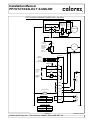
PPT16/22 ALX SINGLE PHASE 230V~1N 50Hz
CONTACTOR
(N/O)
1
(N/O)
3
(N/O)
5
RELAY/HARD
START CAP
1 OFF PPT16
2 OFF PPT22
O/LOAD
2
2
4
4
6
6
96
COMPRESSOR
O/LOAD ALARM
95
SOFT START
THERMAL
OVERLOAD
& FAULT
LIGHT
IF FITTED
C
S
COMPRESSOR
R
RUN CAP
A1
A2
SOFT
START
IF
FITTED
N/C
FAN
13
12
SOLENOID VALVE B
PPT22ALX ONLY
POOL STAT
SENSOR
10
(DEFROST)
12
SENSOR
11
(WATER TEMP)
COMPRESSOR
O/LOAD ALARM
di3
3
97 98
com
C
BREAKS ON
PRESSURE
FALLING
L
HP SWITCH
C
BREAKS ON
PRESSURE
RISING
H
DIGITAL INPUTS
9
LP SWITCH
FLOW SWITCH
di4
(N/C)
4
di1
14
(N/C)
1
15
REMOTE ON/OFF
INTERLOCK
11
SOLENOID VALVE
('Y' VERSIONS ONLY)
(N/O)
di2
2
COM 13
N/O
OUT1
14
COM 18
OUT3
N/O
19
COM 20
21
10
SUPPLY
24
(N)
22
18
FUSE RATINGS
FUSE
3A
PPT22ALX
3A
16
N/C
COM 15
N/O
OUT2
17
19
PPT16ALX
VOLT FREE
POOL PUMP RUN
MAX 3Amps
23
(L)
MODEL
N/O
OUT4
CONTROL FUSE
3A
OVERLOAD SETTING
LIVE
NEUTRAL
MODEL
PPT16ALX
19.0A
PPT22ALX
29.7A
Page 18
Calorex Heat Pumps Ltd. · The Causeway, Maldon, Essex CM9 4XD, UK
SD638153 ISSUE 10
Installation Manual
PPT8/12/16/22LX/LY SLIMLINE
®
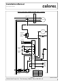
PPT12/16/22 BLX THREE PHASE 400V~3N 50Hz
SOFT
START
IF
FITTED
CONTACTOR
(N/O)
5
(N/O)
3
T2
4
(N/O)
1
T3
6
COMPRESSOR
T1
2
A1
A2
FAN
SOFT START
THERMAL
OVERLOAD
& FAULT
LIGHT
IF FITTED
13
12
SOLENOID VALVE B
PPT22BLX ONLY
POOL STAT
SENSOR
(DEFROST)
10
12
11
SENSOR
di3
(WATER TEMP)
3
com
BREAKS ON
PRESSURE
FALLING
C
HP SWITCH
H
BREAKS ON
PRESSURE
RISING
C
9
FLOW SWITCH
CLOSE ON FLOW
di4
(N/C)
4
di1
15
(N/C)
11
SOLENOID / REVERSING VALVE
L
DIGITAL INPUTS
LP SWITCH
1
14
REMOTE ON/OFF
INTERLOCK
di2
2
COM 13
OUT1
COM 18
OUT3
N/O
14
N/O
19
COM 20
OUT4
N/O
21
10
18
22
16
COM 15
5
6 (N/C)
L3
3
4 (N/C)
L2
1
2 (N/C)
L1
CONTROL
CIRCUIT
BREAKER
L3 L2 L1
N/O
19
OUT2
N/C
17
VOLT FREE
POOL PUMP RUN
MAX 3A (1/2 HP)
SUPPLY
23
24
(L)
(N)
14 (N/O)
12 (N/C)
MCB SETTING
11 (COM)
PHASE
ROTATION
RELAY
MODEL
PPT12BLX
2.0A
PPT16BLX
2.0A
PPT22BLX
2.0A
Page 19
Calorex Heat Pumps Ltd. · The Causeway, Maldon, Essex CM9 4XD, UK
NEUTRAL
SD638153 ISSUE 10
Installation Manual
PPT8/12/16/22LX/LY SLIMLINE
®
PPT22 ALY SINGLE PHASE 230V~1N 50Hz
CONTACTOR
O/LOAD
(N/O)
1
(N/O)
3
(N/O)
5
2
2
4
4
6
6
96
COMPRESSOR
O/LOAD ALARM
95
SOFT START
THERMAL
OVERLOAD
& FAULT
LIGHT
IF FITTED
C
S
COMPRESSOR
R
RUN CAP
A1
A2
SOFT
START
IF
FITTED
RELAY/HARD
START CAPS
N/C
FAN
13
12
POOL STAT
SENSOR
10
(DEFROST)
12
SENSOR
11
(WATER TEMP)
COMPRESSOR
O/LOAD ALARM
di3
3
97 98
C
BREAKS ON
PRESSURE
FALLING
L
HP SWITCH
C
BREAKS ON
PRESSURE
RISING
H
FLOW
SWITCH
9
DIGITAL INPUTS
LP SWITCH
com
di4
(N/C)
4
di1
14
(N/C)
1
15
REMOTE ON/OFF
INTERLOCK
11
di2
2
COM 13
N/O
OUT1
REVERSING VALVE
(N/O)
14
COM 18
OUT3
N/O
19
COM 20
N/O
OUT4
CONTROL FUSE
3A
21
10
18
22
16
PPT22ALY
LIVE
17
FUSE
19
N/O
OUT2
MODEL
N/C
COM 15
FUSE RATINGS
VOLT FREE
POOL PUMP RUN
MAX 3A (1/2 HP)
SUPPLY
23
24
(L)
(N)
3A
NEUTRAL
OVERLOAD SETTING
MODEL
PPT22ALY
29.7A
Page 20
Calorex Heat Pumps Ltd. · The Causeway, Maldon, Essex CM9 4XD, UK
SD638153 ISSUE 10
Installation Manual
PPT8/12/16/22LX/LY SLIMLINE
7.0 Regular planned
maintenance
®
Operations to be carried out during a regular planned maintenance visit are
as follows:
1) Clean the evaporator. (This action may be required more
frequently than regular servicing).
2) Check operation of fan and compressor.
3) Check capacitor tolerances - where fitted.
4) Check condition of all heat exchangers/evaporators.
5) Check refrigeration system parameters.
6) Check operation of control valves.
7) Check for water leaks.
8) Check driptray and internal drain lines for blockages and
flush through if necessary.
9) Check operation of controls and calibrate if necessary.
10) Check operation of interlocks in use.
11) Final check of overall operation of unit
12) Indicate on Service report any faults found or causes for
concern.
13) Recommended servicing frequency:
one visit per year.
Page 21
Calorex Heat Pumps Ltd. · The Causeway, Maldon, Essex CM9 4XD, UK
SD638153 ISSUE 10
Installation Manual
PPT8/12/16/22LX/LY SLIMLINE
8.0 Heat Pump
Malfunction
®
WARNING: Isolate heat pump electrically before entering heat pump or
removing panels.
The user check list should be carried out before initiating a service call.
Do not attempt to interfere with any internal control settings as these have
been factory calibrated and sealed.
Any sign of abnormal operation such as water dripping should be reported
immediately to the installer.
If in doubt or if advice is required contact Calorex Service Department.
Telephone +44(0)1621 857171 or 856611
8.1 User Check List
SYMBOL
The thermostat displays the following lamps during normal operation
DESCRIPTION
LAMP ON
LAMP FLASHING
LAMP OFF
DEFROST
HEAT PUMP IN
DEFROST
-
-
WATER HEATING
DEMAND FOR
WATER HEATING
WATER HEATING
DEMAND
COMPRESSOR DELAY
TIMER NOT
TIMED OUT
NO DEMAND FOR WATER
HEATING/ DEMAND
SATISFIED
FAN
FAN RUNNING
FAN NOT RUNNING
COMPRESSOR DELAY
TIMER NOT
TIMED OUT
FAN NOT RUNNING
AUX
POOL PUMP
POOL PUMP
RUNNING
-
POOL PUMP NOT RUNNING
OFF
OFF LAMP
HEAT PUMP OFF
-
-
If an error occurs any of the following lamps or messages will be displayed.
SYMBOL
DESCRIPTION
LAMP ON
LAMP FLASHING
ACTION
ALARM - FAULT
ILLUMINATES
WITH "to"
-
-
WATER FLOW OFF OR
INADEQUATE
CHECK WATER PUMP
RUNNING AND ANY
EXTERNAL BYPASS VALVES
ARE CLOSED
noF
WATER FLOW
LAMP
WATER FLOW OFF
OR INADEQUATE
to
THERMAL
OVERLOAD
(PPT16/22)
INTERNAL
OVERLOAD TRIP
-
CONTACT COMPETENT
ELECTRICIAN TO RESET
THERMAL OVERLOAD. IF
PROBLEM PERSISTS
CHECK SITE VOLTAGE
PrA
PRESSURE
SWITCH ALARM
HP/LP FAULT
-
CONSULT INSTALLER
SYMBOL
DESCRIPTION
LAMP ON
E1-E1/
E2-E2
PROBE ERROR
EPr
PROBE ERROR
ACTION
PROBE
INTERRUPTED,
SHORT CIRUIT OR
OUTSIDE RANGE
INTERNAL
EEPROM MEMORY
ERROR
CHECK CONNECTION BETWEEN PROBES AND
THERMOSTAT
SWITCH OFF HEAT PUMP AT MAINS SUPPLY FOR
FIVE MINUTES THEN SWITCH BACK ON. IF FAULT
PERSISTS CONTACT INSTALLER
Page 22
Calorex Heat Pumps Ltd. · The Causeway, Maldon, Essex CM9 4XD, UK
SD638153 ISSUE 10
Installation Manual
PPT8/12/16/22LX/LY SLIMLINE
®
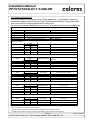
9.0 Datasheets
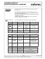
HEAT PUMPS FOR OUTDOOR POOLS SUMMER SEASON (ALX/BLX)
MODEL
Units
PPT8
PPT12
PPT16
PPT22
HEAT TO POOL WATER
AMBIENT 10°C, WATER 24°C
AMBIENT 20°C, WATER 24°C
kWh
kWh
7.2
9.2
9.9
12.5
12.4
15.6
17.7
22.4
ELECTRICITY
ELECTRICAL SUPPLY 1 PHASE
ELECTRICAL SUPPLY 3 PHASE
TOTAL POWER CONSUMED
AMBIENT 10°C, WATER 24°C
AMBIENT 20°C, WATER 24°C
MIN SUPPLY CAPACITY (Max F.L.A.) 1 ph N:-
kWh
kWh
A
MIN SUPPLY CAPACITY (Max F.L.A.) 3 ph N:-
A
6.0
RECOMMENDED SUPPLY FUSE 1 ph N:RECOMMENDED SUPPLY FUSE 3 ph N:-
A
A
20.0
10.0
230V/~1N/ 50Hz
400V/~3N/ 50Hz
1.8
2.0
14.0
2.3
2.5
17.0
2.6
2.8
19.8
4.1
4.3
31.0
6.4
8.0
13.0
25.0
10.0
30.0
15.0
42.0
20.0
WATER FLOWS ETC
POOL WATER FLOW RATE:-
L/min
75
75
125
167
POOL WATER PRESSURE DROP (@ Rated Flow):-
m hd
0.1
0.1
0.1
0.6
bar
2.5
2.5
3.5
3.5
MAX WORKING PRESSURE POOL WATER:POOL WATER CONNECTIONS:CONDENSATE DRAIN CONNECTIONS:-
inches
inches
1 1/2" or 50mm Female
3/4" DOMESTIC WASTE
COMPRESSOR
NOMINAL POWER CONSUMED
L.R.A. 1 ph N:-
kWh
A
1.6
62
2.35
62
2.6
103
3.8
136
R.L.A. 1 ph N:-
A
11.5
13.1
15.8
25
SOFT START AMPS 1 ph N:L.R.A. 3 ph N:-
A
A
28
32
28
30
34
48
37
48
R.L.A. 3 ph N:-
A
4
4.7
7.3
10
SOFT START AMPS 3 ph N:-
A
14
14
25
25
m³/h
2200
3300
3500
4100
A
0.82
0.82
0.82
0.82
GAS CHARGE
R407c
SOUND PRESSURE LEVEL @3m AIR ON
kg
dbA
1.9
53
2.5
54
5.0
53
6.0
54
SOUND PRESSURE LEVEL @3m AIR OFF
dbA
57
55
55
56
SOUND PRESSURE LEVEL @3m SIDE
dbA
50
47
64
52
SOUND POWER
dbA
69.9
67.3
68.2
67.8
*WIDTH (Unpacked):*DEPTH (Unpacked):-
mm
mm
1264
594
1264
594
1264
600
1264
600
*HEIGHT (Unpacked):-
MAIN FAN
AIR FLOW (Anemometer @ air on grille. Dry evaporator):F.L.A. 1 ph N:GENERAL DATA
HERMETIC SYSTEM
*PHYSICAL DIMENSIONS
mm
725
725
725
904
WEIGHT (Unpacked):- ALX
kg
91
96
113
119
WEIGHT (Unpacked):- BLX
WEIGHT (Packed):- ALX
kg
kg
110
96
119
118
142
119
143
WEIGHT (Packed):- BLX
kg
110
119
140
143
FOR ACCURATE APPLICATION SIZING CONSULT CALOREX HEAT PUMPS LTD
NOTES
1) Weight and dimensions nett. * DIMENSIONS INCLUDE WATER IN/OUT STUBS AND MAINS IN CABLE GLAND.
2) Performance design limitations: Ambient = 5ºC min 40ºC max, Water = 10ºC min, 40ºC max.
3) Pool water to have correct balance, pH 7.2-7.8, Free Chlorine 1.0 - 2.0ppm domestic, 3.0 - 6.0 commercial.
4) Allow 500mm clearance to service panels.
5) Calorex reserve the right to change or modify models without prior notice.
6) R407c Global warming potential (GWP) 1700.
1mm WG = 9.8 Pa
1mhd = 1.4 psi
1l/min = 0.22gall/min
Page 23
Calorex Heat Pumps Ltd. · The Causeway, Maldon, Essex CM9 4XD, UK
SD638153 ISSUE 10
Installation Manual
PPT8/12/16/22LX/LY SLIMLINE
®
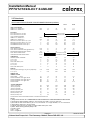
9.0 Datasheets
HEAT PUMPS FOR OUTDOOR POOLS REVERSE CYCLE DEFROST (ALY/BLY)
MODEL
Units
PPT8
PPT12
PPT16
PPT22
HEAT TO POOL WATER
AMBIENT 0ºC WATER 24ºC
kWh
N/A
AMBIENT 10°C, WATER 24°C
AMBIENT 20°C, WATER 24°C
kWh
kWh
7.2
9.20
N/A
N/A
10.7
9.9
12.5
12.4
15.6
17.7
22.4
ELECTRICITY
ELECTRICAL SUPPLY 1 PHASE
ELECTRICAL SUPPLY 3 PHASE
TOTAL POWER CONSUMED
AMBIENT 0ºC WATER 24ºC
AMBIENT 10°C, WATER 24°C
AMBIENT 20°C, WATER 24°C
MIN SUPPLY CAPACITY (Max F.L.A.) 1 ph N:MIN SUPPLY CAPACITY (Max F.L.A.) 3 ph N:RECOMMENDED SUPPLY FUSE 1 ph N:RECOMMENDED SUPPLY FUSE 3 ph N:-
230V/~1N/ 50Hz
400V/~3N/ 50Hz
N/A
2.6
2.8
19.8
8.0
30.0
15.0
3.8
4.1
4.3
31.0
13.0
42.0
20.0
75
125
0.1
0.1
2.5
3.5
1 1/2" or 50mm Female
3/4" DOMESTIC WASTE
167
0.6
3.5
1.6
62
11.5
28
32
2.35
62
13.1
28
30
2.6
103
15.8
34
48
3.2
136
25
37
48
A
A
4
14
4.7
14
7.3
25
10
25
m³/h
A
2200
0.82
3300
0.82
3500
0.82
4100
0.82
GAS CHARGE
R407c
SOUND PRESSURE LEVEL @3m AIR ON
SOUND PRESSURE LEVEL @3m AIR OFF
kg
dbA
dbA
N/A
53
57
N/A
54
55
N/A
53
55
6.7
60
62
SOUND PRESSURE LEVEL @3m SIDE
SOUND POWER
dbA
dbA
50
69.9
47
67.3
64
68.2
58
67.8
*WIDTH (Unpacked):-
mm
1264
1264
1264
1264
*DEPTH (Unpacked):-
mm
594
594
600
600
*HEIGHT (Unpacked):WEIGHT (Unpacked):- ALY
WEIGHT (Unpacked):- BLY
WEIGHT (Packed):- ALY
mm
kg
kg
kg
725
N/A
N/A
725
N/A
N/A
N/A
725
N/A
N/A
N/A
904
141
N/A
162
kg
N/A
N/A
N/A
N/A
WATER FLOWS ETC
POOL WATER FLOW RATE:POOL WATER PRESSURE DROP (@ Rated Flow):MAX WORKING PRESSURE POOL WATER:POOL WATER CONNECTIONS:CONDENSATE DRAIN CONNECTIONS:COMPRESSOR
NOMINAL POWER CONSUMED
L.R.A. 1 ph N:R.L.A. 1 ph N:SOFT START AMPS 1 ph N:L.R.A. 3 ph N:R.L.A. 3 ph N:SOFT START AMPS 3 ph N:MAIN FAN
AIR FLOW (Anemometer @ air on grille. Dry evaporator):F.L.A. 1 ph N:-
kWh
kWh
kWh
A
A
A
A
N/A
1.8
2.0
14.0
6.0
20.0
10.0
L/min
m hd
bar
inches
inches
75
0.1
2.5
kWh
A
A
A
A
N/A
2.3
2.5
17.0
6.4
25.0
10.0
GENERAL DATA
HERMETIC SYSTEM
*PHYSICAL DIMENSIONS
WEIGHT (Packed):- BLY
FOR ACCURATE APPLICATION SIZING CONSULT CALOREX HEAT PUMPS LTD
Page 24
Calorex Heat Pumps Ltd. · The Causeway, Maldon, Essex CM9 4XD, UK
SD638153 ISSUE 10
Page 25
Calorex Heat Pumps Ltd. · The Causeway, Maldon, Essex CM9 4XD, UK
97
204
364.25
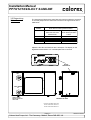
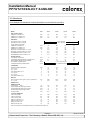
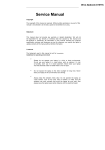
WATER IN
WATER OUT
510.50
AIR ON
854
470
480
70
AIR OFF
165.50
490
594
MAINS IN
CONDENSATE
THERMOSTAT
457
518.50
395
528
1264
1237
PPT8
WATER IN/OUT 1½" or 50mm FEMALE
CONDENSATE ¾" DOMESTIC WASTE
320.50
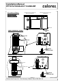
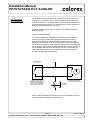
10.0 Installation Drawings
Installation Manual
PPT8/12/16/22LX/LY SLIMLINE
®
SD638153 ISSUE 10
725
46
532
Calorex Heat Pumps Ltd. · The Causeway, Maldon, Essex CM9 4XD, UK
532
435
97
Page 26
364.25
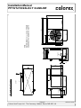
WATER IN
WATER OUT
AIR ON
854
789
470
537.50
70
AIR OFF
165.50
594
490
MAINS IN
CONDENSATE
THERMOSTAT
457
518.50
395
528
1237
1264
PPT12
WATER IN/OUT 1½" or 50mm Female
CONDENSATE ¾" DOMESTIC WASTE
Installation Manual
PPT8/12/16/22LX/LY SLIMLINE
®
SD638153 ISSUE 10
725
320.50
46
Page 27
Calorex Heat Pumps Ltd. · The Causeway, Maldon, Essex CM9 4XD, UK
188
364.25
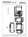
WATER IN
WATER OUT
854
789
AIR ON
AIR OFF
470
641
70
165.50
MAINS IN
600
490
CONDENSATE
THERMOSTAT
457
518.50
395
528
1237
1264
PPT16 1 ½" or 50mm FEMALE
CONDENSATE ¾" DOMESTIC WASTE
Installation Manual
PPT8/12/16/22LX/LY SLIMLINE
®
SD638153 ISSUE 10
725
320.50
97
517
Page 28
Calorex Heat Pumps Ltd. · The Causeway, Maldon, Essex CM9 4XD, UK
364.25
188
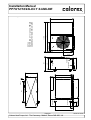
WATER IN
WATER OUT
789
AIR ON
AIR OFF
641
70
844
165.50
490
CONDENSATE
MAINS IN
THERMOSTAT
457
600
394.75
528
1237
1263.50
PPT22
WATER IN/OUT 1½" or 50mm FEMALE
CONDENSATE ¾" DOMESTIC WASTE
Installation Manual
PPT8/12/16/22LX/LY SLIMLINE
®
SD638153 ISSUE 10
904
390.50
470
97
707
Installation Manual
PPT8/12/16/22LX/LY SLIMLINE
11.0 Winterisation
Procedure
®
WARNING. Isolate machine before removing covers!
The heat pump embodies electrical and rotational
equipment, it is recommended for your own safety
that a competent person carries out the following
procedure
ALL MODELS
Objective
To provide frost protection
To eliminate corrosion problems
To inhibit electrical components
1) Switch off electric supply to heat pump.
2) Remove external fuses and keep in safe place away from heat pump to
prevent accidental operation of heat pump.
3) Ensure water circulation pump is switched off.
4) Drain water from heat pump by:
a) drain valve if fitted
b) disconnecting pipework to and from heat pump
5) Flush through water circuit in heat pump by using CLEAN TAP WATER
(NOT POOL WATER) via hose into outlet connection - run the hose for 10
minutes minimum; use spray nozzle if available.
6) Allow to drain - when drained, fit plastic bags secured by elastic bands
over water connections.
7) Uncover electrical enclosure (see section 4.2) and liberally spray interior
of unit, with moisture-repellant aerosol WD40 or similar; reseal enclosure.
8) If heat pump located outside, protect from weather by covering with
VENTILATED cover. Do not use plastic sheet as condensation could
occur within unit.
IMPORTANT
If this procedure is not adopted and frost or corrosion damage
results then the warranty will become invalid.
Page 29
Calorex Heat Pumps Ltd. · The Causeway, Maldon, Essex CM9 4XD, UK
SD638153 ISSUE 10
Installation Manual
PPT8/12/16/22LX/LY SLIMLINE
11.1 Start up Procedure
After Winterisation
®
1) Replace covers (if not fitted).
2) Remove front grille. Using a soft brush clean finned surfaces of heat
pump. Replace panel.
3) Remove plastic covers on water connections and reconnect water
piping or close drain valve.
4) Start up water circulating pump and leave running for at least 1/4
hour to establish flow and enable an air in piping to escape.
5) Replace fuses to heat pump circuit.
6) Switch on heat pump.
7) Check control thermostat is set to required pool temperature.
8) Check pool water daily to ensure it is at correct pH and has correct
chemical balance. (See Section 3 Plumbing).
Page 30
Calorex Heat Pumps Ltd. · The Causeway, Maldon, Essex CM9 4XD, UK
SD638153 ISSUE 10
Installation Manual
PPT8/12/16/22LX/LY SLIMLINE
12.0 Warranty
Conditions
®
The following exclusions apply to the Warranty given by Calorex Heat Pumps
Ltd. No claims will be accepted if : -
1) The heat pump is incorrectly sized for the application.
2) The heat pump is installed in any way that is not in accordance with the
current procedures as defined by Calorex Heat Pumps Ltd.
3) The heat pump has been worked upon or is adjusted by anyone other than
a person authorised to do so by Calorex Heat Pumps Ltd.
4) The air flow to and from the machine is outside the specified limits.
5) The water flow through the machine is outside the specified limits.
6) The water pH level and/or chemical balance is outside the following limits:-
Acidity pH
pH
7.2 - 7.8
Total Alkalinity, as CaCO 3
ppm
80 - 120
Total Hardness, as CaCO 3
ppm
150 - 250
Total Dissolved Solids
ppm
1000 Max
Maximum Salt Content
Free Chlorine Range
ppm
ppm
35000 Max
1 - 2 Domestic
Free Chlorine Range
ppm
3 - 6 Commercial
Superchlorination
max
30ppm for 24 hrs
Bromine
Baquacil
ppm
ppm
2-5
25 - 50
Ozone
ppm
0.9 Max
Maximum Copper Content
Aquamatic Ionic Purifier
ppm
ppm
1
2 Max
7)
The heat pump has suffered frost damage.
8) The electrical supply is insufficient or in any way incorrect.
Page 31
Calorex Heat Pumps Ltd. · The Causeway, Maldon, Essex CM9 4XD, UK
SD638153 ISSUE 10
Installation Manual
PPT8/12/16/22LX/LY SLIMLINE
13.0. Contacting
Calorex
®
Email: [email protected]
Website: http://www.calorex.com
Tel:
+44 (0)1621 857171 or +44 (0)1621 856611
Please give MODEL NUMBER and SERIAL NUMBER of your heat pump
when making technical or service enquiries. This will assist in correct
diagnosis and ensure service can be provided with the minimum delay.
Page 32
Calorex Heat Pumps Ltd. · The Causeway, Maldon, Essex CM9 4XD, UK
SD638153 ISSUE 10
Installation Manual
PPT8/12/16/22LX/LY SLIMLINE
®
14.0 Machine Record Log
In order to comply with European Union F-Gas regulations, it is necessary to leak test
hermetically sealed systems with more than 6kg refrigerant annually. The operator of the
unit is responsible for seeing that the test is carried out.
For machines affected see datasheet section 9.0. A sample log sheet can be seen below.
General Information
Plant Name
Location of Plant
Plant Operator1
Operator Contact 2
Refrigerant Type
Plant manufacturer
Serial Number
Calorex Heat Pumps Limited
Refrigerant Quantity installed (kg)
Year of installation
Refrigerant Additions
Date
Engineer3
Company
Name
Amount Added kg
Reason for addition
Amount Removed kg
Reason for removal What done with recovered
refrigerant
Engineer
Company
Name
Test Result
Follow up action required
Engineer
Company
Name
Related to test on
Actions taken
Refrigerant Removals
Date
Engineer
Company
Name
Leak Tests
Date
Follow up Actions
Date
Testing of Automatic Leak Detection System (if fitted)
Date
Engineer
Company
Name
Test Result
Comments
1
Name and address of company operating plant.
Contact details for operator's nominated person responsible for F Gas compliance.
3
Company and technician carrying out work, with details to provide evidence of compliance.
2
Page 33
Calorex Heat Pumps Ltd. · The Causeway, Maldon, Essex CM9 4XD, UK
SD638153 ISSUE 10