1
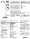
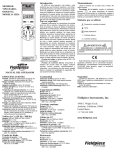
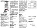
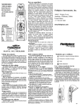
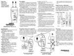
DIGITAL MULTIMETER
Model: LT16A
MAX
MIN
LT16A
TRUE RMS PHASE ROTATION
AUTO-OFF
CAPACITANCE
V
V
A
A
MFD
2A
MFD
L1
L2
FUSED
2A
MAX
CAT.III
MAX
600V
15 SEC FOR 200mV
MAX
RANGE
500V 3 PHASE
600V FOR 3O SEC
General description
For your safety...
Overload protection
The LT16A is an excellent true RMS digital multimeter for testing motors and electrical equipment.
The LT16A meter measures current, resistance,
voltage, capacitance, frequency, continuity, and
phase rotation. Test leads store within the meter
and can connect the LT16A to Fieldpiece accessory heads. The body is made out of durable ABS
plastic and comes with an alligator clip test lead for
measuring phase rotation. It also has a backlight.
General: Inspect the test leads for damage to the
insulation or exposed metal. Replace if suspect. Never
ground yourself when taking electrical measurements.
Do not touch exposed metal pipes, outlets, fixtures,
etc., which might be at ground potential. Keep your
body isolated from ground by using dry clothing, rubber
shoes, rubber mats, or any approved insulating material. When disconnecting from a circuit, disconnect the
"RED" lead first, then the common lead. Work with others. Use one hand for testing. Turn off power to the circuit under test before cutting, unsoldering, or breaking
the circuit. Keep your fingers on the plastic and behind
the ridge of the probes.
600VAC/DC rms
for 15 sec
>200mV range 600VAC/DC rms
600VAC/DC rms
Phase Rot.
for 30 sec
2A/600V fuse
AAC/DC
(6.35X25.4mm)
model RFM70
0.25A/500V fuse
Capacitance
(6.3X32mm)
model RFM66
Resistance
500VAC/DC rms
Diode Test
500VAC/DC rms
Continuity
500VAC/DC rms
User maintenance
Battery Replacement: When the multimeter displays the "
" the battery must be replaced to
maintain proper operation. To prevent electrical
shock, turn off the meter and disconnect leads
before removing the back cover.
Fuse Replacement: When only certain ranges
quit working, check the fuse. Open the case and
replace according to the Overload Protection chart.
All other repairs must be performed by a
Fieldpiece service center
L3
All Voltage Tests: All voltage ranges will withstand up to 600VAC or 600VDC. Do not apply more
than 600VDC or 600VAC.
AC Tests: Disconnect the meter from the circuit
before turning any inductor off, including motors,
transformers, and solenoids. Hi voltage transients
can damage the meter beyond repair. Do not use
during electrical storms.
Safety: Designed to meet IEC 61010-1
(EN61010-1), CATIII 600V, Class II, pollution deg.2,
indoor use. CE UL61010-1. C-Tick certified.
Symbols used:
!
OPERATOR’S MANUAL
Caution, refer to manual.
Ground
Double insulation
General specifications
DC voltage
Resistance (ohms)
Auto-off: off after 25 minutes to extend battery.
Indicators: Continuity beeper (<100Ω). Low bat.
Overrange: "OL" or “-OL” is displayed.
Operating environment: 32 to 122°F (0 to 50°C)
<70%RH
Storage environment (with batteries removed): -4 to
140°F (-20 to 60°C) <80%RH
Altitude: 6561.7 feet (2000m).
Battery life: 150 hours typical.
Battery type: 9V NEDA 1604 type
Stated accuracies: 74°F±8°F (23°C±4°C), 75%RH
Temperature coefficient: 0.1 x (specified accuracy)
1°F/°C (32 to 66°F (0-19°C), 82 to 122°F (28-50°C)).
Ranges: 200mV, 2000mV, 20V, 200V, 600V
Resolution: 0.1mV
Accuracy: 0.5%±1
Input impedence: 10MΩ
Ranges: 200Ω, 2kΩ, 200kΩ, 20MΩ, 2000MΩ
Resolution: 0.1Ω
Accuracy: 1.0%±4 (200Ω to 200kΩ ranges),
2.0%±4 (20MΩ range),
(5.0%-10)+10 (2000MΩ range)
Open circuit voltage: 0.3VDC typical, (3.0VDC
on 200Ω and 2000MΩ range)
MIN/MAX
Record the minimum or maximum reading during a
measurement. To exit the MIN/MAX function, hold the button for more than 2 seconds.
Backlight
Always be very careful when testing in the dark. You
should always have a separate light on the area you are
testing. The backlight will shine for 4.5 minutes when the
backlight button is pressed.
True RMS
Digital multimeters use one of two types of AC sensing.
The most common is average sensing, normalized to a true
RMS value of a sine wave. The other is true RMS sensing.
The actual true RMS value is sensed for a wave form within the limits of the crest factor. True RMS is needed to calculate power. Either sensing method will give the same
results on a clean sine wave but they may differ on a nonsinusoidal waveform.
AC voltage True RMS (50Hz-500Hz)
Ranges: 200mV, 2000mV, 20V, 200V, 600V
Conversion: True RMS
Crest factor: Less than or equal to 3
Resolution: 0.1mV
Accuracy: 1.5%±5(200mV to 20V ranges),
2%±5(200V, 600V ranges)
Input impedence: 10MΩ
DC Current (through meter)
Ranges: 200μA, 20mA, 200mA, 2A
Resolution: 0.1μA
Accuracy: 1.0%±1 (200μA to 200mA ranges), 2.5%±1
(on 2A range)
Voltage burden: 800mV
AC Current True RMS (through meter)
Ranges: 200μA, 20mA, 200mA, 2A
Crest factor: Less than or equal to 3
Resolution: 0.1μA
Accuracy: 1.5%±5 (200μA to 200mA ranges), 3.0%±5
(on 2A range)
Voltage burden: 800mV
Frequency (autoranging)
Range: 10Hz to 40KHz
Resolution: 1Hz
Sensitivity: 3.5V rms min
Accuracy: 0.1%± 3
Diode test
Accuracy: 1.5%±3
Test current: Approx. 1.0mA
Open circuit voltage: 3.0VDC typical
Capacitance (MFD)
Ranges: 200μF, 2kμF, 20kμF
Resolution: 0.1μF
Accuracy: 4%±10
Test frequency: 21Hz
Test voltage: <3.0V
Phase rotation
Range: 80VAC to 500VAC (45Hz to 450Hz)
This function enables you to connect 3-phase
power to the correct leads of a motor to insure the
motor turns in the intended direction. The terminals
the motor are marked L1, L2, and L3. The wires
supplying power are not marked. Connect meter
jacks marked L1, L2, and L3 to the power wires in
any order. Make sure all three leads are connected
(L1, L2, and L3 will be “on”). “OK” indicates “for-
VAC/DC
200mV range
Service
Call Fieldpiece Instruments for one-price-fix-all
warranty service pricing. Send check or money
order for the amount quoted. Send the meter freight
prepaid to Fieldpiece Instruments. Send proof of
date and location of purchase for in-warranty service. The meter will be repaired or replaced, at the
option of Fieldpiece, and returned via least cost
transportation.
www.fieldpiece.com
ward”. Connect L1 on the meter to L1 on the motor,
L2 on the meter to L2 on the motor, etc. The motor
will turn in the direction designed. If you get “ER”
(reverse), swap any two leads. It should then say
“OK.”
Limited warranty
This meter is warranted against defects in material
or workmanship for one year from date of purchase.
Fieldpiece will replace or repair the defective unit, at its
option, subject to verification of the defect.
This warranty does not apply to defects resulting
from abuse, neglect, accident, unauthorized repair,
alteration, or unreasonable use of the instrument.
ANY IMPLIED WARRANTIES ARISING OUT OF
THE SALE OF A FIELDPIECE INSTRUMENT’S
PRODUCT, INCLUDING BUT NOT LIMITED TO
IMPLIED WARRANTIES OF MERCHANTABILITY
AND FITNESS FOR A PARTICULAR PURPOSE, ARE
LIMITED TO THE ABOVE. FIELDPIECE SHALL NOT
BE LIABLE FOR LOSS OF USE OF THE INSTRUMENT OR OTHER INCIDENTAL OR CONSEQUENTIAL DAMAGES, EXPENSES, OR ECONOMIC LOSS,
OR FOR ANY CLAIM FOR SUCH DAMAGE, EXPENSES, OR ECONOMIC LOSS.
State laws vary. The above limitations or exclusions
may not apply to you. This warranty gives you specific
legal rights, and you may also have other rights which
vary from state to state.
v14
How To Use Your Multimeter
For DC voltage and currents, set the meter to the DC parameter instead of AC as shown to the left. For all ranges and functions choose range just above value
you expect. If display reads "OL” or “-OL" (overload), select a higher range. If display shows less than three numbers, select a lower range for better resolution.
Voltage
V
Amps
V
Microamps
Resistance & Continuity Beeper
COM
V
V
A
VW
A
MFD
V
COM
2A
2A
V
V
COM
V
A
COM
A
A
VΩ
A
A
MFD
A
MF D
MFD
Frequency
V
AC Current Clamp
Capacitance (MFD)
V
V
V
V
COM
AC
H4
!
A
A
A
MFD
MF D
A
MFD
A
A
ClaC C
u
VW
m rr
1A
p en
40 AC
t
0A / 1
AC mV
MA AC
X
A
VΩ
V
MFD
30
0V
40
0A
COM
Optional accessory heads
Fieldpiece accessory heads convert the desired
parameter into a millivolt signal. For example, the
ARH4 converts one °F into one milli-volt DC. The
multimeter must then be set to read millivolts DC.
One exception is the ACH4 current clamp which
must be set to read AC millivolts. Any digital multimeter with these scales can be used in conjunction
with Fieldpiece Accessory Heads.
Use Fieldpiece deluxe silicone test leads
(model# ADLS2) with removable probe tips to use
the accessory heads with the LT16A.
CL
AM
P
CA
T.III
COM
Phase Rotation
V
Diode Test
VW
V
COM
V
Accessory Heads
V
L1
V
A
A
L2
A
MFD
V
A
ON
LCD X
100
LO BATT
READ
Metric
Real
time
STABLE
Air
Conditioner
Superheat
and Subcooling
Air Velocity
& Temperature Average
English (16 sec)
Head
MFD
L3
A
English
Metric
Ft/min
MPH
ºF
M/s
KM/hr
ºC
VΩ
COM
SH
ENGLISH
SC
METRIC
400A
SH or SC
Temp
Pressure
OFF
AUTOOFF
A
MF D
ON
LO BATT
R22
R410A
300V
CLAMP
CAT.III
AC Current
Clamp
1AAC / 1mVAC
400AAC MAX
AAV3
AUTO OFF
Set
ATM
T/C
Cal
!
ARH4
ACH4
ASX14
AUTOOFF